| John Broskie's Guide to Tube Circuit Analysis & Design |
18 October 2009
The Good Old Days In fact, the more time I spent in libraries and used book stores, the lower the Present Age fell in my estimation, while the '40s, '50s and early '60s rose in my assessment. I liked how the unisex look was unknown then, how women dressed like women and men dressed like men; and how the young dressed young; the middle aged, middle aged; and the old, old. Moreover, I wholeheartedly agreed with the '50’s admiration of the hour-glass curvy figure of movie stars like Ava Gardner, Gina Lollobrigida, Grace Kelly, Marilyn Monroe, and Rita Hayworth. And I much preferred the the strong, silent leading men of the '50s to the plaintive and neurotic antiheroes of the '60s and '70s, such as Woody Allen. In terms of music, '40s and '50s jazz walked all over '70s jazz, as far as my ears, mind, and heart were concerned. As I searched back through more old magazines in the hunt for audio knowledge, I grew ever fonder of the '50s aesthetic in magazine layout and typography, with its clean, open, and friendly look. Indeed, I slowly grew to appreciate '50s fashion, cars, and prose; I had begun to notice that the newer the textbook or magazine article, the more poorly it was written. And, last but not least, I longed for the low crime and prosperity of the '50s. I remember reading in Harpers magazine (at least I believe it was Harpers) a list of the top problems facing high schools back in the '50s. At the top of the list were stomach-wrenching problems that not even the world's most capable community organizer could hope to solve, such as chewing gum and being in the hallways without a pass. Today’s list boasts much more tractable problems, as befits the hugely greater investment we make in education today and the '50s lack of a United States Department of Education (created in 1979), problems such as murder, rape, arson, drugs, illiteracy… Ah, indeed, those days of old when tubes glowed bold.  Source: FBI, Uniform Crime Reports, 1950-2005
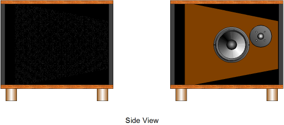
Stereo Cabinets
The actual unit I saw at the garage sale was immaculate, having sat in storage for decades, and came complete with brochure, sales receipt, and owner’s manual. And it weighed over a hundred pounds. Sadly, it was from the mid 1960s and held solid-state amplification, so I wasn’t even tempted by its $50 price tag. But it did get me thinking about the stereo cabinet and what it could look like if made today. Today, a stereo cabinet could never be as frilly or ornate, but it could still look expensive. It could house small high-power class-D power amplifiers and big sub woofers and high-end woofers and tweeters. In addition, WiFi reception would be essential, as having no Hi-Fi wires is optimal. Here is what I would love to build, if I had the tools and the time:
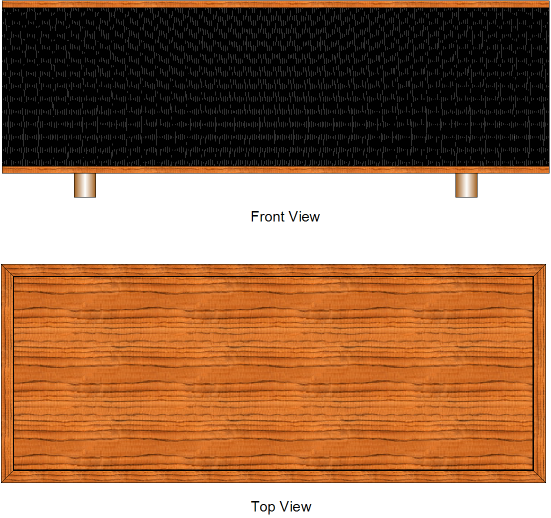
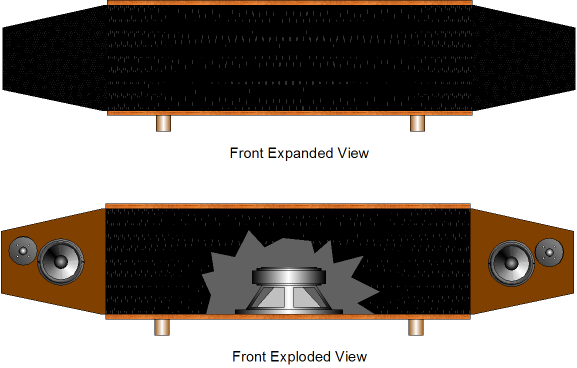
The cabinet would be about five feet wide and a foot and half tall and almost two feet deep. Inside a single down-firing subwoofer would finds its own 300W amplifier. At each end, a dipole loudspeaker comprising a 7” to 8” woofer and tweeter would project their sounds to the flanking walls. Well, at least they would while the cabinet was in casual-listening mode. For serious listening and audiophile friend impressing, the dipoles would pivot and extend out, facing the listener. When fully extended, the side panels would lock tightly in place.
When folded back into the cabinet, the side panels would also lock tightly in place and their rear radiation would work into a small, well damped volume of air, while still venting at the panels’ sides.
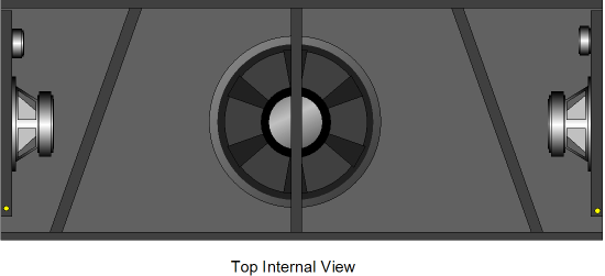
The following shows the internal arrangement, with its three divisions, with a center cross brace.
Where’s the stereo gear? The CD player? The turntable? The tuner? The big tube-filled power amplifiers? All of the above could rest on top of the cabinet, but more likely they wouldn’t be needed, as Logitech Duet and a few class-D power amplifiers would suffice. The WiFi connection would allow streaming of internet radio and a thousand CDs could be ripped to a computer hard drive. In fact, the music server computer could be easily built into the cabinet, with a large LCD screen either sitting atop the cabinet or built into the front and hidden by grill cloth when not in use. (I love the look of black-tinted glass resting on black felt, as it seems to imply infinity in its shiny darkness. Thus, by replacing the front grill cloth assembly with black glass and felt, an LCD screen could remain hidden until turned on behind the glass. Or like the old stereo cabinets, a center leaf could open to reveal an LCD screen. Or imagine the same dark glass front, but with many vacuum tubes warmly glowing behind the glass panel.)
Even More Impedance-Multiplier Circuitry
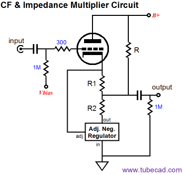
Another way of increasing the current delivery into a load is to use a single impedance-multiplier circuit and alter the impedance-multiplier ratio in favor of the tube, letting the solid-state impedance-multiplier circuit do a larger share of the work.
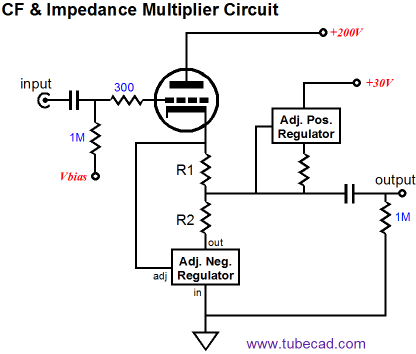
The addition of resistor R allows the impedance-multiplier circuit to draw much higher current than the tube can safely pass. For example, a 6SN7 could idle at 5mA, while the adjustable voltage regulator at the heart of the impedance-multiplier circuit could idle at 10mA, as long as the extra resistor made up the difference in current flow into the b+ connection. In other words, if the tube draws 5mA and the impedance-multiplier circuit draws 10mA, then the added resistor R must draw 5mA. In fact, we could even use a 12AX7 (idling at 1mA) and an impedance-multiplier circuit (idling at 50mA), if resistor R conducts 49mA, as is shown below.
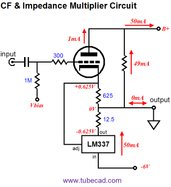
What’s the point of grounding the output? A load of zero ohms is a great place to start, as it lays bare the mathematical relationships within the circuit. Note that at idle, the ground sees no net current flow, neither into the negative or power supply power supply rail. Most importantly, note how the tube and the negative-voltage regulator split the regulator’s 1.25 reference voltage equally between themselves. This is critical, as we want the tube’s entire symmetrical current swings to be mirrored and greatly amplified by the impedance-multiplier circuit. In other words, as the tube ceases to conduct, the impedance-multiplier circuit should be at its maximum conduction.
Conversely, as the tube conducts fully, the impedance-multiplier circuit should cease its conduction.
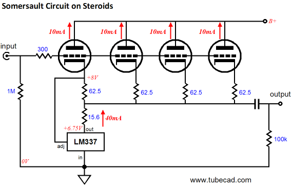
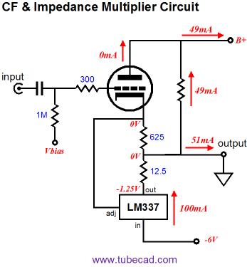
What happens when the external load is something greater than 0-ohms? Doesn’t the added resistor R cease to draw a constant current, as it will no longer see a fixed voltage across its leads? The current through the resistor R must vary with the voltage swing at the output, but if the B+ voltage is high, the variation is likely to prove small, as the most likely the external load will be a low-impedance headphone driver, which although requiring large current swings, need only see small voltage swings, only a volt or two. The bigger problem with use of resistor R is heat. For example, 49mA against 200V results in 9.8W of heat. The following schematic shows a clever workaround.
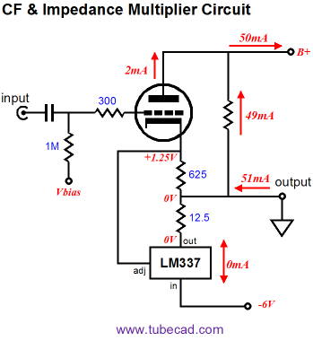
The added resistor R has been replaced by a constant-current source made up from another voltage regulator (a negative regulator could just as easily be used). Assuming that the impedance-multiplier circuit and the constant-current source split the 30V rail voltage, the constant-current source will only dissipate 735mW of heat. A single 12AX7 supercharged by fiftyfold. What could be better? Well, you should consider this aspect of this arrangement: the tube is only doing 1/51 of the work, the solid-state devices, 50/51 of it. Does this mean that we have a 1.96% pure OTL? When the impedance-multiplier circuit merely doubled the effective load impedance, the tube did 50% of the work. Of course marketing departments were never good at math, so they will have no problem describing 1.96% as 110%. But will our ears agree with their math?
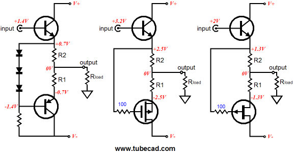
Solid-State SRPP+ Output Stages
Did you catch the name of Mr. Bellamy's circuit, "Transistor switching circuit responsive in push-pull manner to single-ended input." I guess that TSCRPPMSEI was just too long, so SRPP came to be was used instead. Also note how just PNP transistors are used. Why? Back in the early 1960s, the only power transistors readily available were the PNP type. Within the text of his patent, Mr. Bellamy makes note that NPN and NPN-PNP combinations were also possible. So it seems that although the tube-based SRPP topology was invented by Maurice Artzt (US patent 2,310,342) back in 1943, "SRPP" the name was first applied to the Transistor version and then backwards given to the tube version. It looks as if Bellamy just performed a translation of the tube SRPP circuit into silicon, but I will have to read the patent more carefully to see if he recognized the implicit impedance-multiplier circuit within the SRPP. Nonetheless, like the tube-based SRPP, the solid-state versions benefit from the “plus” treatment, the addition of a second current-sensing resistor, which make explicit the impedance-multiplier-circuit nature latent in the SRPP.
While searching for patents of solid-state SRPP-type circuits, I found the SRPP+. In 1964, Mr. Sukehiro Ito applied to patent a circuit named Push-Pull Amplifier Operated with One Input, US 3,328,713 (awarded in 1967).
The zener, Z1, uses the old schematic symbol. Our two friends, resistors R1 & R2, make their first appearance, but with their labels reversed. If only Mr. Ito’s use of two current-sensing resistors had made the backward development into the tube-based SRPP back in 1964, the SRPP+ could have been incorporated in scores following tube designs in the last 40 years. By the way, during my patent hunting, I discovered that, in 1999, Sony had reinvented the Taylor amplifier and patented it! Patents EP 0 963 038 A2 (1999) and US 6,392,454 (2002). Interestingly enough, they refer to it as an SRPP circuit! In fact, it is a variation on the White cathode follower theme. In 1973, P. L. Taylor wrote an article titled "Audio Power Amplifier," in Wireless World's June issue. His amplifier actually includes a few design features missed by Sony. Since only 23 years had passed and since Wireless World was one of the world's premier electronic magazines, you might imagine that Sony's patent application would be denied due to prior art It's best not to get me started on the failings of the patent system.
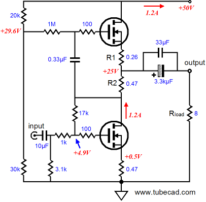
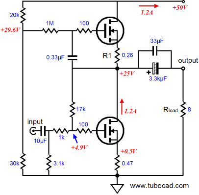
Zen² MOSFET Power Amplifier
If we remove resistor R2, the amplifier reverts to a Zen amplifier, single-ended amplifier in other words. (A cool feature might be to use a switch to short resistor R2 in and out of the circuit—but not while the amplifier is on!)
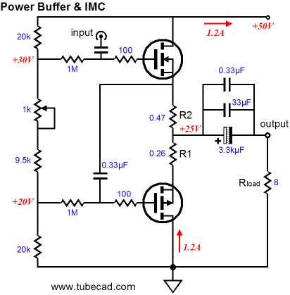
By removing resistor R2, the top MOSFET now functions as a constant-current source, not a push-pull companion. (What could be cooler than to build a tube-based SRPP+ line stage amplifier to drive a MOSFET-based SRPP+ power amplifier? The 756-ohm input impedance of the power amplifier would be a perfect load for the tube SRPP+ amplifier.) By the way, we can easily create a high-power, push-pull, unity-gain buffer with MOSFETs and the impedance-multiplier circuit topology. In the following schematic, we see the impedance-multiplier circuit function moved to the bottom half of the circuit. Note how the R1 and R2 resistor values remain the same. If the P-channel MOSFET could offer infinite transconductance, the two resistor values would match. But as the MOSFET’s transconductance is limited, R1’s value must be decreased to compensate.
(This time, an Aikido amplifier would be the right choice as the amplifier's frontend.) Such a power buffer is intriguing, but never forget that it must operate in strict push-pull, class-A mode, wherein the idle current must equal at least half the peak expected current swing into the external load. In other words, hot and big; heavy and expensive. On the other hand, the high input impedance is a welcome change from the previous power amplifier's low iput impedance. //JRB |
Kit User Guide PDFs
And
High-quality, double-sided, extra thick, 2-oz traces, plated-through holes, dual sets of resistor pads and pads for two coupling capacitors. Stereo and mono, octal and 9-pin printed circuit boards available.
Designed by John Broskie & Made in USA Aikido PCBs for as little as $24 http://glass-ware.stores.yahoo.net/
The Tube CAD Journal's first companion program, TCJ Filter Design lets you design a filter or crossover (passive, OpAmp or tube) without having to check out thick textbooks from the library and without having to breakout the scientific calculator. This program's goal is to provide a quick and easy display not only of the frequency response, but also of the resistor and capacitor values for a passive and active filters and crossovers. TCJ Filter Design is easy to use, but not lightweight, holding over 60 different filter topologies and up to four filter alignments: While the program’s main concern is active filters, solid-state and tube, it also does passive filters. In fact, it can be used to calculate passive crossovers for use with speakers by entering 8 ohms as the terminating resistance. Click on the image below to see the full screen capture.
Tube crossovers are a major part of this program; both buffered and un-buffered tube based filters along with mono-polar and bipolar power supply topologies are covered. Available on a CD-ROM and a downloadable version (4 Megabytes). Download or CD ROM
|
|||


| www.tubecad.com Copyright © 1999-2009 GlassWare All Rights Reserved |