| John Broskie's Guide to Tube Circuit Analysis & Design |
06 November 2009
A. J. van Doorn's New Amplifier: the Octode Mr. van Doorn names his new design the Octode Amplifier.
Let me begin by stating that I am only going to give a quick gloss of Mr. van Doorn’s new design, as I want you to read his article first. (My own policy has always been to read the reviews only after seeing the movie, play, or book. So, after a few months pause, we will probably revisit the octode amplifier.)
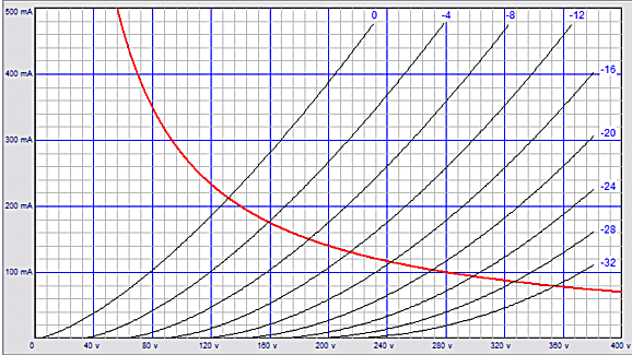
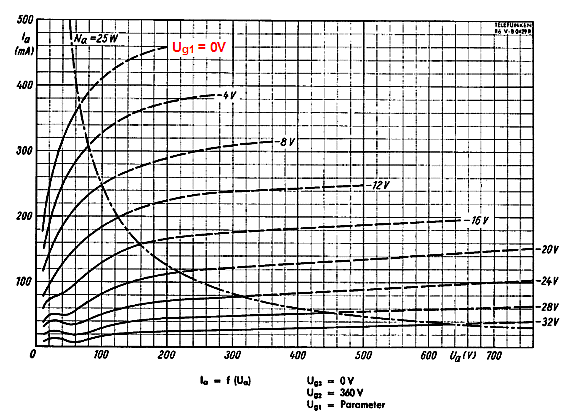
Mr. van Doorn’s goal is to wed the triode’s linearity and low output impedance to the pentode’s big power delivery. The triode cannot compete with the pentode in the power race, because the triode gives up half of the potential voltage and current swings that a comparable pentode can fully exploit. In other words, if we compare the plate curves for the triode and pentode, we see that the 0-volt grid line bisects the graph, in the triode’s case; and encompasses most of the graph, in the pentode’s case. So, should the pentode swing twice the current into a load over the triode, the pentode’s power output will be four times bigger than the triode’s.
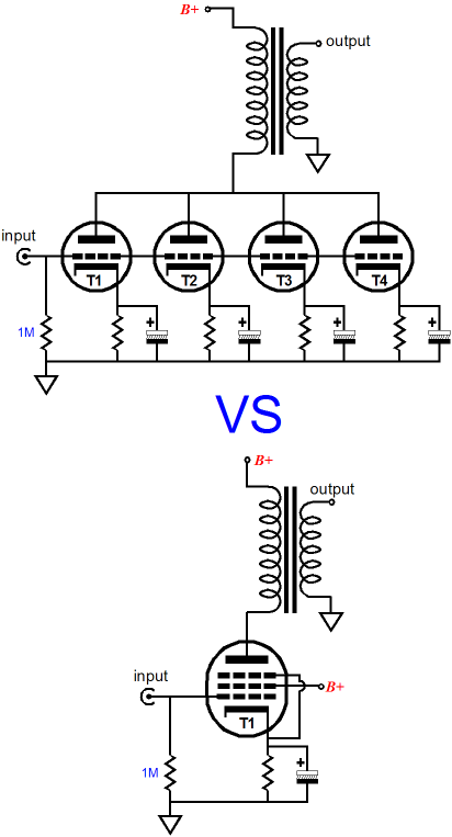
For example, a triode-connected EL34, in a push-pull power amplifier might be able to muster 15W at its output, whereas a pair of pentode-connected EL34s in the same amplifier could easily yield 50W to 70W. By the way, all the following circuits will be shown in single-ended configurations, as the push-pull output stages take up twice the space in this all-too-narrow column.
Running both triode and pentode in parallel might seem the way to go, as both tube types would work into the same load and both should bring some of their positive attributes to the job. This approach has been tried before and few commercial amplifiers have been sold using this setup.
The alternative approach has been to use an ultra-linear output stage, wherein a single pentode behaves as if it consisted of a triode in parallel with a pentode. This makes sense, as when the UL ratio approaches 100% the tube becomes a pure triode; at the other extreme, the screen attached to the B+ connection, a pentode. By setting the ratio somewhere between 10% to 50%, the output stage offers a good amount of power and fairly low distortion.
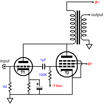
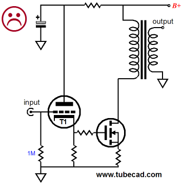
Mr. van Doorn, however, seeks more triode and less pentode in terms of sonics, but without sacrificing the high potential power that pentodes can deliver. His novel topology confers upon the triode the task of controlling the pentode’s output. The pentode’s input signal derives from the signal the triode superimposes on its cathode resistor, which is then amplified by a second triode and then given to the pentode’s grid.
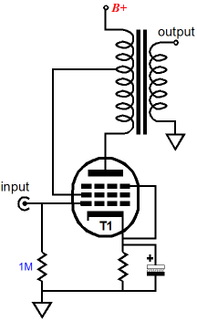
I like the look of this arrangement, as triode T1’s non-linearity does not cascade directly into the pentode as it does in the following schematic.
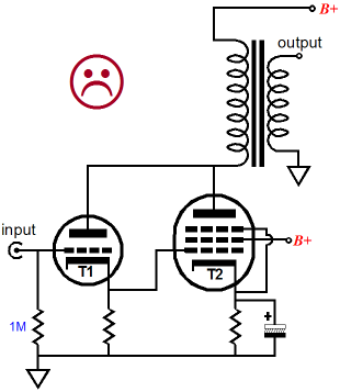
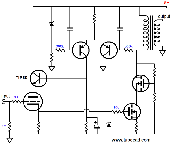
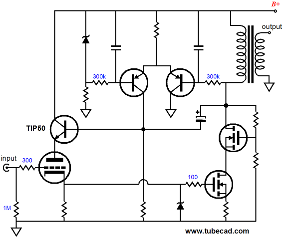
How does the second triode iron out the first triode’s non-linearity? Both triodes and pentodes are easier to turn on than they are to turn off. This means that the signal the triode passes on to the pentode in the above schematic will over-emphasize the positive-going swings over the negative-going ones. In turn, the pentode will overreact to these overly positive-going signals. In other words, the distortions compound. In van Doorn’s amplifier, however, the intervening triode amplifier stage works to undo the first triode’s distortion, as the grounded-grid amplifier works in anti-current phase to the grounded-cathode amplifier. I discovered for myself the distortion-compounding effect when I experimented with the following circuit about twenty years ago. I had just acquired a handful of 1200V N-channel power MOSFETs and I was eager to use them in a single-ended amplifier. (My goal was to get something close to 30W from the amplifier, but with a relatively low B+ voltage of about 400Vdc.)
The sound from this prototype was interesting but sad. It definetely had an SE amplifier's easy, dymanic sound, but the texture was wrong, sounding too hard, too edgy in the highs and too fat in the bass. I had actually cascaded two MOSFETs with a two-resistor voltage divider connected from the triode’s plate to ground, with the 50% division point attaching to the top MOSFET’s gate—as I feared toasting the solid-state devices with high-voltage inductive spikes. I also used the voltage drop across the output transformer primary's DCR as DC signal to set the idle current through the MOSFET via PNP-based differential amplifier and NPN-based emitter follower that regulated the triode's plate voltage. (Just one of many examples of my being too clever for my own good.)
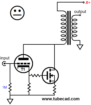
I disliked the sound so much that I tried the amplifier without the triode and drove the bottom MOSFET's gate directly (with a coupling cap and bias voltage) and the sound was much improved. What I should have built was something much more along van Doorn's Octode design, with the input triode's plate tied to the MOSFET's drain. Why? The triode would have then controlled the MOSFET, rather than just passed on a tube-soaked signal. In other words, by tying the plate and drain together the two devices complete a feedback loop, with the triode's plate resistance (rp) and amplification factor (mu) working together to keep the MOSFET's transfer curve in line. For example, by itself, the MOSFET offers almost no resistance to the change in drain voltage; but with the triode's plate attaching to the drain, the triode will buck changes in voltage at its plate by increasing and decreasing its conduction, which in turn the MOSFET will greatly amplify.
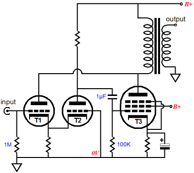
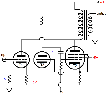
(By the way, in the previous schematic, imagine the the triode still using the auto-bias circuitry, but with the emitter follower's decoupling capacitor connecting to the primary, rather than ground.) I should stop right now, as I want to encourage you to read Mr. van Doorn’s article first. I will, however, leave with one small thought experiment: What if we attached the second triode’s grid in the Octode amplifier not to ground but to the pentode’s unbypassed cathode resistor?
Once again, please do buy this issue of audioXpress; it's definitely worth the money. Speaking of audio-construction magazines, after about a six year run, I have let my subscription to MJ lapse. This is a great Japanese audio magazine, what Christian Rintelen has described to me as a shinning example of tube porn, as most of us, not knowing Japanese, can only look at the pictures (I read it for the schematics...yeah, sure). I like the magazine a great deal, but it is hugely expensive to buy with wimpy US dollars (shipping alone was over $100 a year). And to be frank, it hasn't wowed me with anything spectacularly interesting in years. Still, I am sad to forgo its monthly arrival. No doubt, the last few issues have been stellar And if you wish to read up on the topic of dissimilar amplifiers, download the PDF that I wrote a few years ago: Mixed Amplifiers.
Tetra Phono Preamp
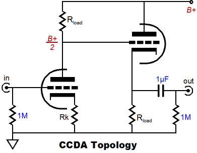
Of course, if the CCDA's alternative cathode resistor(s) configuration is used, the one wherein the the cathode follower's cathode resistor terminates in the the cathode of the the input tube, then the listed Rk values must be halved.
//JRB |
E-mail from GlassWare Customers
High-quality, double-sided, extra thick, 2-oz traces, plated-through holes, dual sets of resistor pads and pads for two coupling capacitors. Stereo and mono, octal and 9-pin printed circuit boards available.  Aikido PCBs for as little as $24 http://glass-ware.stores.yahoo.net/
Only $19.95
Download or CD ROM
|
||||||||||||||||||||||||||||||||||||||||||||||||||||||


| www.tubecad.com Copyright © 1999-2009 GlassWare All Rights Reserved |