| John Broskie's Guide to Tube Circuit Analysis & Design |
| Post 199 30 January 2011
I planned to reveal this electronic trope—scheme, grouping, figure, composition, pattern, configuration—last year, but the year flew past me. The inception for this circuit cluster began when I tried to come up with new uses for the 12DW7/ECC832/7247 tube. (This dissimilar-triodes tube effectively holds 12AX7 and 12AU7 triodes in one envelope and the current production version from JJ is quite good.) A quick side trip. In the study of rhetoric, figures of speech are divided into two groups: schemes and tropes. Schemes refer to the shape, the pattern of words in some text or speech. We can invert the usual word order and make a bigger impression as a result. For example, "And the swan dies after many a summer" is just ok; but "And after many a summer dies the swan" is snazzy and all the more memorable because of the word order inversion (from the poem Tithonus by Alfred Tennyson). A trope, on the other hand, refers to a change in the usual meaning of words. Examples can readily be gleaned from puns, irony, euphemism, hyperbole; for example, "he had a zit literally as big as watermelon"—really, actually as big as a watermelon or would a pea be closer to the truth? (In fact, whenever you encounter the word "literally," it most likely means not literally. Just as "very" often means not very, as in "I am very sure I parked the car somewhere near here.") Well, in the art and practice of electronics, we rearrange components into distinguishable patterns, such as two triodes or two FETs or two transistors into a differential pair or two transistors into a Darlington pair.
Cascoded devices are also such a recognizable scheme. These device configurations are portable, transferable to other devices and other existing circuits. Here is where technique reigns triumphant. Moreover we can use electronic devices in uncommon roles, for example, rectifiers and LEDs can be used as cheap voltage references; a light bulb's filament, as an inductor or power resistor; and pairs of twisted wires, as a low-valued capacitor. Sometimes the altered use is subtle. For example, as 99% of hybrid power amplifier use tubes for voltage amplification and solid-state output devices for current gain, a startling inversion would be a hybrid power amplifier that used transistors for voltage gain and tubes for current gain. Or we might build an inverted-use amplifier that used a 300B as the input tube, a 2A3 as the phase splitter, and twenty 5687s as the output tubes. Here is where art sneaks in. I have heard circuits described as witty, sneaky, whimsical, and entertainingly clever at one extreme; at the other extreme, stodgy and stolid, perverse, warped. In fact, if told that someone found the schematic to the latest Audio Research power amplifier indigestible, I would have no problem knowing what was meant. Sometimes the an electronic scheme is locked into place in a single device, such as with three-leaded Darlington transistors or tubes like the 6J6, which holds two identical triodes intended for use in a differential amplifier, whose cathodes come tied together within the glass envelope, allowing a 7-pin base to be used. In other words, if the electronic scheme is truly portable, then it could be hardwired into a meta device, like the IGBT or Darlington transistor. Remember A.J. van Doorn's Octode, which I covered in blog number 176?
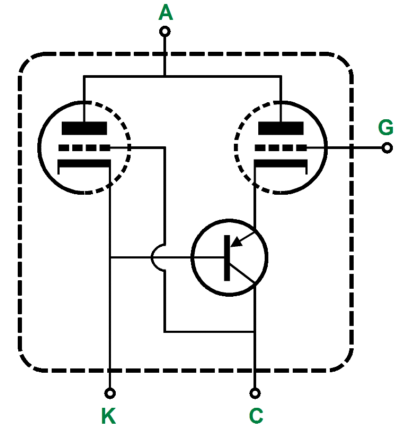
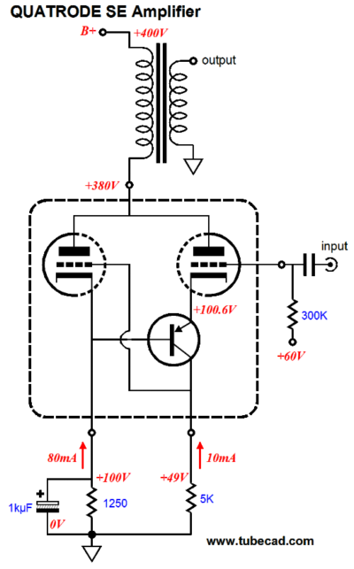
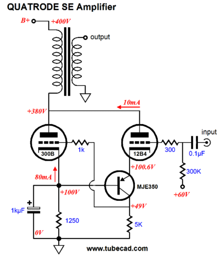
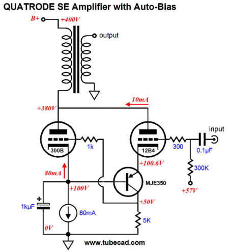
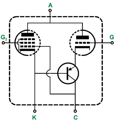
His goal, too, was the creation of a reusable arrangement of three tubes. A good test portability is could (and should) the topology be held within a compactron tube envelope. (A good example of a compactron is the 6AF11, a tube that encased a high-mu triode for AGC use, a medium-mu triode for sync separator use, and a sharp-cutoff pentode for the video amplifier.) Well, this is how I want the Quatrode viewed: as a portable, transferable electronic scheme that can find wide application in many different types of circuits. Here is one possibility, an SE power amplifier. Quatrode Single-Ended Power Amplifier Here is one possibility, an SE power amplifier. The triode on the right controls the triode on the left, much like the super-triode circuits I have shown before. A change in either or both the right triode's grid or plate voltage will cause a change in its current conduction. This variation in current flow is then relayed to through the PNP transistor to the collector resistor, which in turn is relayed to the left triode's grid. In other words, the right triode is cascoded by the PNP transistor.
Hold on there Mr. Platinum Brain, you cannot use a 12DW7 in a single-ended amplifier that runs 90mA through the output transformer. True enough. Once again, just as figures of speech are not tied to specific words (And after many an hour before the TV dies the imagination), electronic topologies are not tied to specific parts, but freely find wide application with many varied devices. Okay, okay, so what tubes would you use? The old standard, the 300B, is an obvious choice for the output tube. The harder choice is finding the best driver tube, as few small tubes can withstand a steady 280Vdc of cathode-to-plate voltage.
(By the way, for those readers who insist that all amplifier schematics must read from left to right, with the input at the extreme left and the output at the extreme right, I must apologize. But at the same time, it is good to challenge and stretch your mind every once in a while.) The 12B4 is a great little power triode and it will see all the voltage swings that its big brother, the 300B, sees. The MJE350 PNP transistor is a fine high voltage device and it will live comfortably within its 100V window of operation. Note how the 5k collector resistor and the 1250-ohm cathode resistor set the 300B's bias voltage at the midpoint of that 100V window, which is essential; as the output tube must see big symmetrical voltage swing to ensure full output. (A subtlety would be to shift the voltage division upwards, so that the 300B's grid could see a larger negative voltage swing than a positive swing; due to the triode's nonlinearity, it is easier to turn the triode on than to turn it off. In this example, we would scale up all the operational voltages by 10V, so the B+ voltage would 410Vdc; the plate voltage, 290Vdc; the 300B cathode voltage, 110Vdc, the 300B grid bias voltage, 59Vdc. Thus, the output tube's grid could see maximum positive grid voltage swing of +51V and a maximum negative swing of -59V.) By the way, since we have breached the purity of an all-tube design by including the PNP transistor, we can further sully the all-tube chastity by using a constant-current source to set the output tube's idle current.
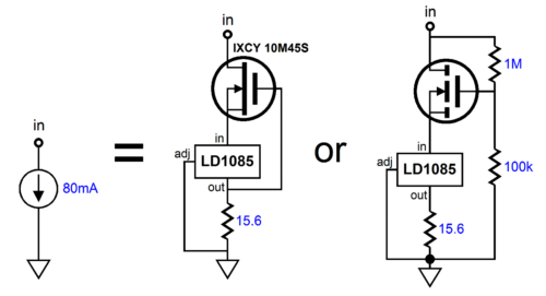
But where do I buy a 10W 80mA constant-current source? You assemble one out of discrete parts.
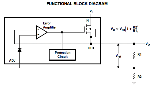
The IXCY 10M45S is a depletion-mode MOSFET that in itself can be used a constant-current source, but I find that setting the idle current to be rather hit or miss, so I prefer to let the LDO LD1085 (or LT1085) set the current flow. On the other hand, a beefier, high-voltage, power MOSFET can be used (enhancement-mode) by adding a two-resistor voltage divider. In this last example, the constant-current source would be functional up to 330Vdc. I just did a quick search of the Texas Instrument's website and I was surprised to see the TL783 still in production. This is a great high voltage three-pin voltage regulator. I used to use them all the time decades ago in semi-high voltage designs. From the TI website:
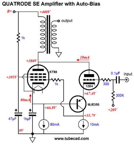
(I would love to see TI come out with a 500V version, which would have been impossible back in 1981 when the device was created, but should be a breeze today. In fact, if I remember correctly, TI did make a special extra-high-voltage version of the TL783, which was good for up to 170Vdc.) The internal reference voltage used in the TL783, however, is slightly higher than the usual 1.25V of three-pin voltage regulators, being about 1.27V, so the idle setting resistor value would be about 15.8 ohms. By the way, since the triode on the right controls the triode on the left, we could use a pentode on the left side and let the triode on the right control it, while still imparting a triode flavor to the sum and getting a lot more power at the output.
Note the greater efficiency of the KT88 in terms of needed grid drive over the 300B and note the addition of a constant-current source load for the input stage. Usually adding a constant-current source load to a cascoded stage is a bit dangerous, as the gain will approach infinity, but the 12B4's plate connection to the KT88's plate creates a DC/AC negative feedback loop, which keeps everything inline.
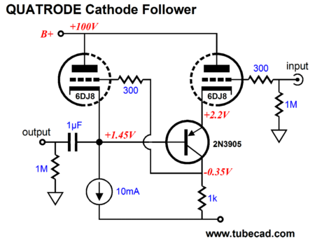
Quatrode Baby Steps: the Cathode Follower
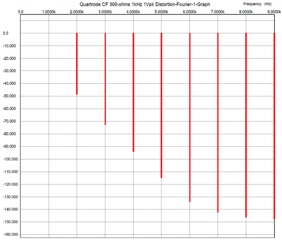
A -6Vdc power supply rail is used, but not shown in the above schematic. Once again, an apology for the right-to-left schematic and for pointing out that 2A3 or 845 tubes could be used in the Quatrode, not just 6DJ8s (it kills me when some reader writes me asking if a 6SN7GTB or 12SN7 will work in the schematic that displays a 6SN7—or how about a Chinese brown-based 6SN7 instead of a Russian brown-based 6SN7?). This hot-rodded cathode follower boasts a tenfold lower output impedance than the stock cathode follower with the same tube and operating currents and voltages. The tenfold decrease comes from the input 6DJ8's transconductance against the 1k collector resistor. If a 2k resistor had been used, the decrease would have been twentyfold. The distortion is also much lower than the stock version. The following is a SPICE simulation graph for the above circuit with a 300-ohm load and 1Vpk @ 1kHz.
Not bad, not bad at all. As with all feedback systems, the path to better performance lies in the direction of more gain. We could increase the negative rail voltage to from -6Vdc to -100Vdc, which would allow a 20k collector resistor to be used, increasing the gain by twentyfold.
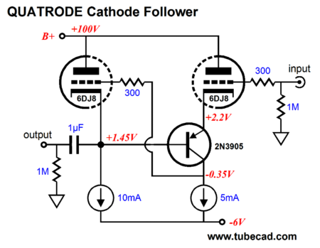
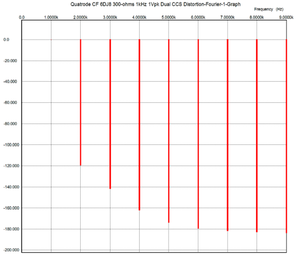
Or we could replace the collector resistor with a constant-current source, as shown above, which would vastly increased the gain; thereby vastly reducing the output impedance and distortion, as the following graph makes clear.
Amazingly good results. Here is a homework assignment: work out the THD from the above Fourier graph.
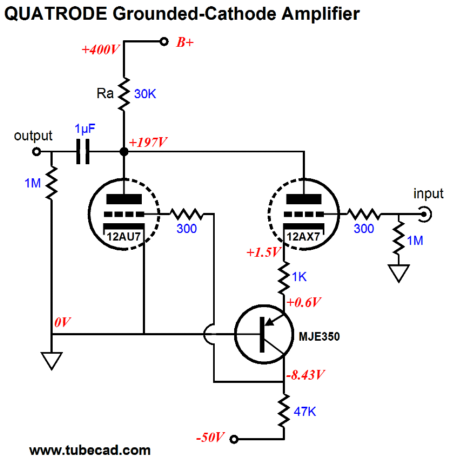
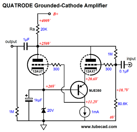
Quatrode Grounded-Cathode Amplifier
Making a Quatrode-based grounded-cathode amplifier that forgoes the negative power supply rail is only a bit more complicated.
The 250Vdc plate voltage is locked into place by the 20V zener and the two-resistor voltage divider at the input tube's grid. The voltage gain from this setup approaches the mu of the 12AX7-half of the 12DW7, about 95, even with a 47k external load. The distortion is only a fraction of what the conventional grounded-cathode amplifier would yield, not that the stock version could ever deliver the high gain, low distortion and output impedance that this Quatrode-based grounded-cathode amplifier produces.
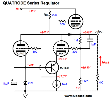
Quatrode High-Voltage Series Regulator
Once again, a 20V zener is used as an internal voltage reference and a two-resistor voltage divider sets the output voltage. The 1µF shunting capacitor across the 1M resistor increases the AC feedback, thereby lowering the output impedance at frequencies above 0.16Hz. In this example, the external load draws 40mA of current. The pass tube is the sturdy 6AS7, although a 6C33 or PL509 (or 12B4 if you do not need a lot of current) could be used instead. Indeed, a high-voltage, power MOSFET could be used just as easily.
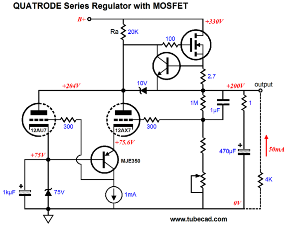
The N-channel MOSFET bestows many advantages, such as a lower output impedance and a greater output current and a much wider range of voltage operation. The MOSFET, however, does present a few liabilities. For example, I have accidentally shorted the output of my HP high-voltage, all-tube regulator a few times, yet the regulator survived. I am not sure the MOSFET would. The added NPN transistor at its gate and the 2.7-ohm source resistor help limit the maximum output current to about 250mA. And the 10V zener also sets a limit to the maximum source-to-gate voltage the MOSFET can see. Nonetheless, I would be nervous. Moreover, what happens at start up, when the tubes are cold and not conducting, will the output voltage start at the raw B+ voltage and, then, slowly fall to the desired regulated voltage? What is needed is slow start circuit or output relay that only actuates when the tubes are up and running. (The potentiometer allows fine adjustments to the output voltage.) Quatrode High-Voltage Shunt Regulator
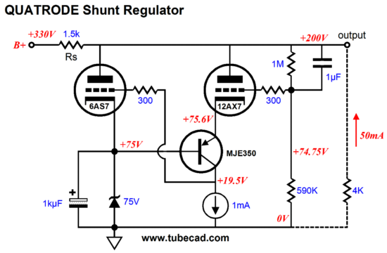
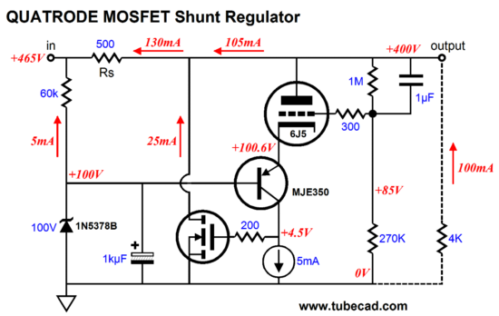
Note how the zener voltage has been increased to 75V and how the voltage divider resistor values have been changed accordingly. In addition, in this example, the load current has been upped to 50mA. Of course, this shunt regulator would benefit from some serious capacitor bypassing of its output; but for the sake of clarity, I omitted the capacitor. From here, it is a small jump to a Janus-like shunt regulator.
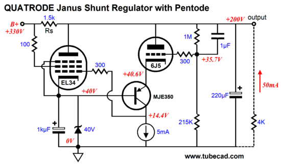
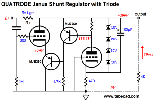
Using a power triode as the shunting tube in a Quatrode Janus regulator will require driving the triode's cathode, rather than its grid.
Imagine if I had started this blog entry with this circuit! Although many have become dizzy, it is not as bad as it looks. Just pretend that the shunting triode's grid was grounded, rather than attaching to the raw DC. Now, look at how the zener string at the right control the right triode's conduction. If the output voltage climbs above 200Vdc, the right triode will cease to conduct, which in turn will turn off the top MJE350 PNP transistor, which will then pull down the bottom MJE350's base, causing the transistor to greatly increase its conduction, thereby causing the shunting triode to pull its plate voltage way down. Conversely, if the output voltage falls below 200Vdc, the right triode will conduct too much, causing the top MJE350 to also conduct too much, turning off the bottom MJE350 and shunting triode as a result, which will force the output voltage upward. By the way, if we remove the zener string, the regulator will still scrub AC perturbations from its output, but it would no longer provide a fixed output voltage. This might not be the big liability it seems, as we often are not that concerned about the absolute DC voltage, being much more worried about low output impedance and low AC noise.
Before moving on, let's look a pure shunt regulator with no Janus action or Quatrode topology. Instead of using a power triode or pentode, this regulator uses a high-voltage, power MOSFET.
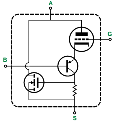
Of course, we might have started with this scheme. In which case, the Quatrode symbol would look like this:
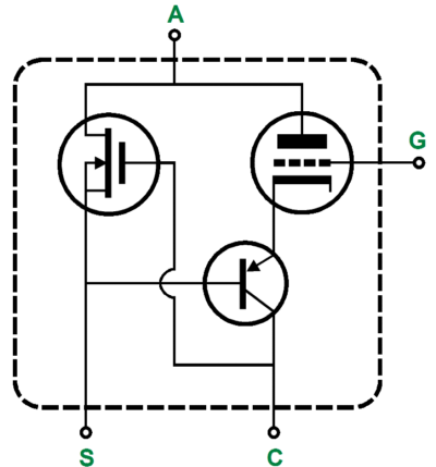
Then again, if we used a depletion-mode MOSFET, we could get closer to the original Quatrode configuration:
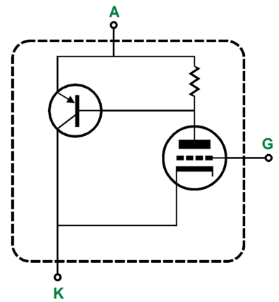
Or how about a Three-ode:
Or a Quintode:
Dear God, make him stop; my head is exploding... As they say, given enough time, pencils, and paper...
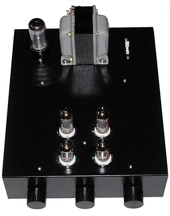
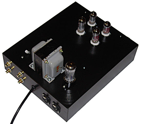
Next Time By the way, I am putting together an interesting piece of tube gear that will interest many TCJers. I will not say what it is, as I just cannot take anymore e-mail. (This site is getting well over a million hits a month, about 400k a week, which garners a ton of e-mail.) But I will leave you with a few photos of it. From the front. From the back.
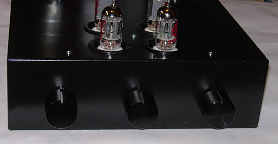
I just love those fat, heavy, cold knobs. It's pity those are the only three I own.
//JRB |
|
I know that some readers wish to avoid Patreon, so here is a PayPal button instead. Thanks.
John Broskie
E-mail from GlassWare customers:
And
High-quality, double-sided, extra thick, 2-oz traces, plated-through holes, dual sets of resistor pads and pads for two coupling capacitors. Stereo and mono, octal and 9-pin printed circuit boards available.  Aikido PCBs for as little as $20.40 http://glass-ware.stores.yahoo.net/ Only $12.95
Version 2 Improvements *User definable Download or CD ROM www.glass-ware.com To purchase , please visit our Yahoo Store |
||


| www.tubecad.com Copyright © 1999-2011 GlassWare All Rights Reserved |