| John Broskie's Guide to Tube Circuit Analysis & Design |
| 18 May 2013
Flea-Power OTL Amplifier Stop and consider how strange an outcome this is.
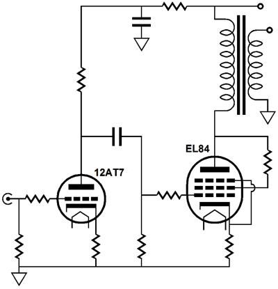
The purpose of a power amplifier is to deliver power into a loudspeaker; thus, one might assume that the more powerful amplifier must always win a shootout, just as the bigger caliber rifle must always out shoot the smaller bore rifle. Not so, of course. The real test of an accurate rifle is can it hit the target, not how big a hole it makes in it. And an agile flea-powered amplifier can often accomplish more direct hits than a lumbering brute of a power amplifier can ever hope to match. So, in spite of not being able to shake the house's cornerstones free or prompt bleeding from our ears, flea-power amplifiers can beguile and charm even the most jaded audiophile; indeed, particularly the jaded; much like the jaded Casanova, who after years of seducing unblushing babes, finds himself most captivated by a virginal ingénue, the audiophile who has owned as many big power amplifiers as most women have own shoes, can find himself most moved, most startled, and most confused by the delicate and sweet watts pouring from a flea-powered amplifier. There is an old saying "to put a flea in someone's ear," which in America it means to severely rebuke someone, but in fourteen century France, it meant something altogether different: "used to describe the practice of provoking desire in someone else. In a rather lewd French poem, the poet writes about putting a flea in a young woman's ear in the sense of causing her to become intoxicated with desire." Well, I hope that I have put a flea in your ear, so that you feel the urge to give an excellent-sounding flea-power amplifier a listen, if you haven't already. What constitutes a flea-power amplifier? Power output far below the average might work as the defining characteristic. But power is relative. In a world of 300W class-D power amplifiers, all tube amplifiers are below average. And many solid-state-loving audiophiles would snigger that the idea of using a pitiful 60W amplifier, whereas many tube-loving audiophiles would delight at having so much power. An arbitrary rule might be that any power amplifier that puts out 10W or less watts is a flea-power amplifier. By the way, a solid-state flea-power amplifier can be made (and should be made). I bet that many of the Nelson Pass inspired Zen amplifiers would meet the maximum-of-10W rule. Over thirty years ago, I listened to a Southwest Technical headphone amplifier that put out only 2.5W. Based on the size of the power transformer and heatsinks, it looked very much like a 25W solid-state power amplifier; but due to the severe restrictions the true class-A operation had imposed, its output was limited to 2.5 watts. I listened to it with some loudspeakers and I was surprised by how much sound it produced. And I was quite pleased with the quality of the sound, velvet smooth and agile. Moreover, anyone who owns a 2A3-based single-ended amplifier is listening to a flea-power amplifier, as is anyone with a single 300B single-ended power amplifier. The following is what I would consider an archetypal flea-power amplifier.
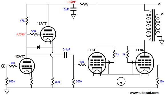
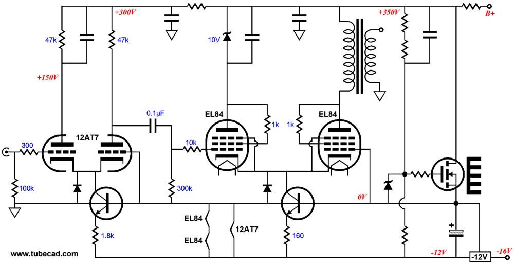
Note the complete absence of electrolytic capacitors—they are absent from the RC filter and the input and output tubes cathodes. Such an amplifier cannot put out more than 3W, but such an amplifier can sound shockingly mellifluous, with extra emphasis on the honeyed aspect. Of course, further refinements are possible. The following is more along the lines of what I would build.
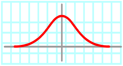
Where to start? Note that the 12AT7-based cathode follower seemingly does nothing, as nothing attaches to its output. So why did I include it? The goal was to unburden the RC filter by creating a constant-current-draw input stage. If the RC filter does not see a signal-induced variation in current, then it will have far less work to do (and can do less harm). The second noteworthy item is the cathode-coupled output stage. The constant-current source creates both an auto-bias feature and a means to better couple the two cathodes, which will improve the PSRR and lower the distortion. To be honest, the only thing that I don't like about this output stage is the even number of output tubes, as I would prefer an odd number. Of course, an additional power tube could be used as a shunt-regulator pass device. This is a flea-power amplifier that I would love to listen to. Before moving on, I should explain why I believe flea-power amplifier can perform so well. With tube-based amplifiers, two answers immediately come to mind: single output tubes (in single-ended amplifiers) and small output transformers (in both single-ended and push-pull amplifiers). A single output tube often gives the impression of a less confused sonic presentation, which is often jumbled by the addition of more output tubes in parallel with it. Now here is the paradox: while two output tubes in parallel often sound worse than a single tube, many output tubes, say five or more, in parallel can sound also better than two output tubes in parallel. It's almost as if the two parallel tubes exaggerate the differences between the tubes, while many parallel tubes seem to emphasize what they share in common. The analogy I make is that of a TV and two viewers, each armed with his own remote control. As the DVD plays on, the two viewers vie with each other, each making his preferred adjustments to the picture's color, brightness, and contrast. The result is not pretty. On the other hand, given twenty viewers, each armed with a remote control, their efforts at adjustment would define a bell curve of preference, with the majority winning.
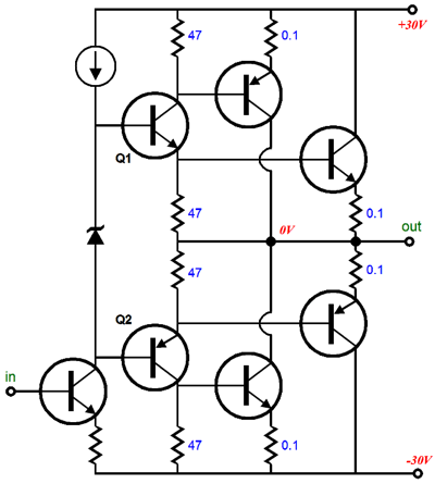
Of course, if two output tubes are truly matched, not just at one bias point, then the two in parallel should sound as good or, possibly, better than a single tube. By the way, in the solid-state world, there is a group of power amplifier designers who hold that a single pair of NPN-PNP output transistors sound best and that many parallel output transistors creates the dreaded solid-state sound. I tend to agree with them, as the sweetest solid-state power amplifiers I have heard used a single pair of complementary output transistors. Another group holds, however, that it was big mistake to have ever used complementary output transistors (dissimilar devices) in a push-pull design, as NPN and PNP output transistors never truly define a complementary pair. (Most tube-circuit designers have long bemoaned the lack of a P-version the triode and pentode, but maybe they were lucky not to have gotten their wish.) Well, solid-state power amplifiers can be designed that exclusively use NPN bipolar transistors (or exclusively PNP types) or N-channel MOSFETs in the output stage, but one clever topology uses both at once! The following is a simplified version of what I have seen in the truly excellent Bryston power amplifiers, for example.
Brsyton calls the topology Quad-Complementary. Yes, it does look complex, but this configuration is really quite simple. Transistors Q1 and Q2 are used as split-load phase splitters, with each NPN and PNP output transistors getting its required input signal. The result is that the NPN and PNP output transistors work both in parallel and in opposition to each other, which establishes a true balance between the two device types. The downside to this circuit is that it sacrifices a small amount of potential voltage swing at the output, which is of little concern in a mega-watt power amplifier. Indeed, I would argue that it should be of little concern in a flea-power amplifier as well. I would love to hear an 8W flea-power amplifier that used this output stage topology, particularly if it ran in class-A.
As for small output transformers versus big output transformers, I readily admit that fine-sounding big output transformers exists; in fact, I own a large collection of them (Tango, Peerless, Dyanco, Harman Kardon Citation II). Nonetheless, I unwaveringly believe that it is much harder to design and build a great-sounding big output transformer, whereas it is much easier to design and build a sweet-sounding tiny output transformer. Where's the proof? An acquaintance of mine long ago explained to me how the best sounding output transformers were those ridiculously small 3W single-ended output transformers that were found in old hi-fi consoles from the 1950s. What! From their appearance alone we can conclude that little effort was used in either their design or construction. At the time, I was sure that he was wrong, but after I actually listened to them, I discovered that he was far more right than wrong. (In addition, I have been told that a maker of extremely expensive and large tube power amplifier uses a big potted output transformer that hold seven small pancake output transformers in parallel; so although the big tube power amplifier puts out a good amount of power, you are still listening to a small output transformer, albeit many small transformers in parallel.) Now the question of why do small output transformers sound so good arises. My guess is that they hold a higher copper wire to iron ratio. The iron core may be necessary, but it is not ideal, as an ideal output transformer would hold an air-core. Well, small output transformers must also be high-ratio transformers, as the single or pair of output tubes require a high-impedance load. Thus, the small output transformer must hold a lot of wire to achieve the high winding ratio. In contrast, a 200W output transformer expects to see many KT88 output tubes in parallel, which create a low plate resistance and require a low winding ratio. In other words, the big output transformer's ratio between copper and iron favors iron; the small output transformer, copper. Another feature in favor of the flea-power amplifier is that they are usually quite simple, whereas most big power amplifiers are hugely, bewilderingly complex. Obviously, the bigger and more complex anything is, whether it be a company, bureaucracy, social event, system of laws, or electronic assembly, the easier it is to botch-up.
I remember a gifted chef explaining to me how most Mexican restaurants butcher guacamole by doing too much to it. A few high-quality ingredients can make a spellbinding dish, whereas buckets full of many poor-quality ingredients make cafeteria food. Of course, not all complex designs are the mess which General Motors or the US tax code are. You, for example. You live. You develop and learn. You are amazingly complex. And sometimes the only solution is a complex solution, regrettable as that might be. I am only saying that we should proceed with caution. Indeed, I am so often startled and bemused by the e-mails that I receive that constitute the most amazing mix of supremely complex notions with the embarrassing want of fundamental understanding. For example, someone might write asking for help in designing a 1,000W tube power amplifier that uses a three-phase power supply and switching voltage regulators for the B+ and screens and negative bias and a CPU powered bias management system that uses multiple ADCs that monitor every aspect of the amplifier, including the ambient air temperature and wall voltage; the only problem is that the writer doesn't know what a resistor does in a circuit. But he is sure that once he does, the rest will be a piece of cake. For some reason, after reading such an e-mail I am always compelled to remember that wonderful Mozart story:
The following circuit is an example of a complex flea-power amplifier that might just sound fantastic, but it may also hold some unforeseen trap.
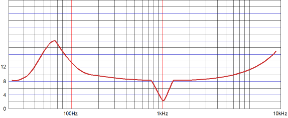
(The shunt regulator uses a high-voltage MOSFET and the fixed -12V power-supply rail as a voltage reference. The diodes at the cathodes only engage when the tubes have yet to conduct at startup. The pixels are not even dry and I have already thought of a few improvements to the above circuit; amazing.) Let's do some easy math. To find the require plate voltage that would allow the 6AS7 to deliver 160mA into 150 ohms we use this formula: Vp at idle = Ipk(rp + Rload). Plugging in the variable values and we get 68.8V, which we then round up to 100Vdc. Thus, in a totem-pole configuration, wherein one triode sits atop another, the required B+ would be 200Vdc. Whoa! That's a heck of a round up. Indeed, but the extra B+ voltage buys us some insurance against sagging B+ voltages, under prolonged stress. In addition, the extra B+ voltage will help out if the loudspeaker's impedance falls below its nominal 8 ohms, which it most certainly will. Remember an IMC will multiply whatever impedance it encounters. And with the exception of some planer and ribbon speakers, no speaker defines a resistor-like 8-ohm resistance; instead, the average speaker's impedance versus frequency plot looks like a fun roller coaster ride.
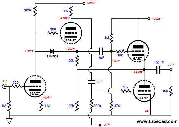
The next problem to solve is What should the idle current be for this output stage? With a plate dissipation limit of 13W, we could run up to 13W/100V or 130mA. But a more reasonable amount would be 80mA, which would result in only 8W of dissipation (or about 60% of the maximum), which would ensure a much longer life span for the output tube. In addition, 80mA means that the OTL will operate in class-A, as 80mA is half the peak current flow. Now, all that is left is a suitable topology. The following OTL circuit is simple and effective. The input tube is a 12DW7 (ECC832), which comprises a 12AX7 triode and 12AU7 triode. The 100µF coupling capacitor allows bandwidth down to about 11Hz with the 150-ohm load, which is based on the following formula: C = 159155/R/F, where C is the capacitance in µF and R is the load resistance and F is the -3dB bass frequency.
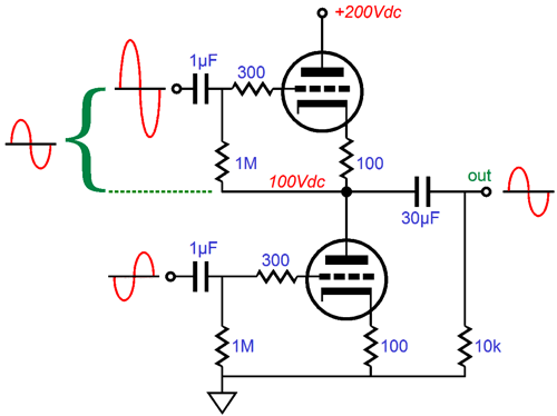
The input triode halves the B+ voltage available to it, which is essential to ensure a high PSRR, as we want both top and bottom output triodes to see an identical amount of power-supply noise at their grids. Because the first stage split the B+ voltage, it also splits the power-supply noise, so the phase splitter will put out half of the B+ ripple at each of its two outputs, same magnitude and same phase, which the output stage then largely ignores. The split-load phase splitter terminates into the output, which will allow it to automatically attain the required ratio of drive signal amplitude to both output triodes. In other words, it feeds the top triode a much larger signal than it feeds the bottom triode. Why? The top triode's cathode moves with the output signal, whereas the bottom triode's cathode is fixed.
The above schematic illustration is an old one, so the 100-ohm cathode resistors will not be used in the OTL. On the other hand, 10-ohm cathode resistors are a very good idea when using the 6AS7. Why? The 10-ohm cathode resistors prevent current runaways, as they impose a degenerative negative feedback mechanism. In other words, if the triode draws too much current, the 10-ohm cathode resistor develops a big voltage drop, which makes the cathode more positive relative to the grid, which works to turn off the excessive conduction.
OTL Power Supply
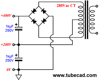
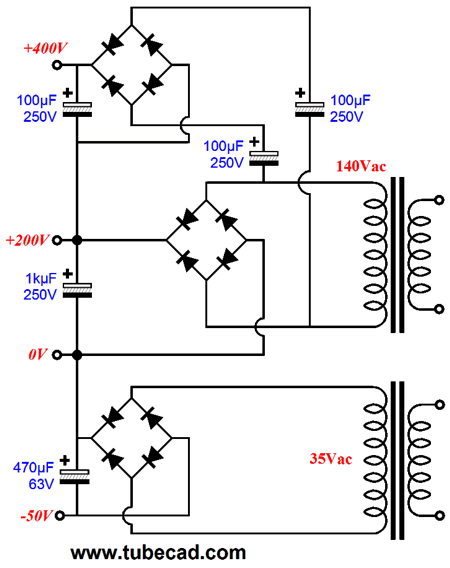
Note that the center-tap is NOT grounded. Some habits are hard to die, but this power supply would die if the habit of always grounding the center-tap were not broken. What is missing is a negative power-supply rail for the negative bias voltage needed for the bottom 6AS7 triode. The following power supply creates the required three power-supply rail voltages.
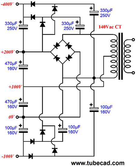
Note how no center tap was needed. The punch line is that there are many ways to get three power-supply rail voltages. For example, here is how we can get three power-supply rail voltages from a single center-tapped secondary.
Of course, what is missing is the heater power supply, which might be as little as single 6.3Vac winding or something altogether more complex.
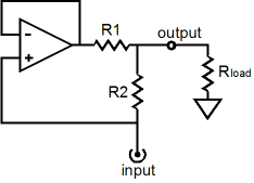
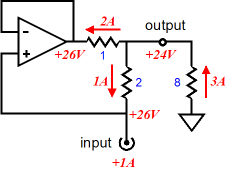
Impedance Multiplier Circuit
It offers an input and an output. At the output a loudspeaker (or headphone driver) attaches; at the input an external amplifier's output is received. The two resistors set the impedance ratio. If the two resistors are the same value, the IMC will effectively double the load resistance's impedance. If the ratio between the resistors is 2, as in the IMC example below, then the impedance ratio will equal 3, so the 8-ohm load reflects through the IMC as a 24-ohm load to the external power amplifier. Now, if the ratio between the resistors is 19, then the impedance ratio will equal 20, so an 8-ohm load effectively becomes a 24-ohm load to the external amplifier.
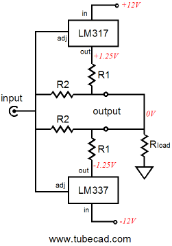
The IMC can be made from a unity-gain stable power amplifier, even a chip amplifier such as the LM12,* or from two voltage regulators, as shown below.
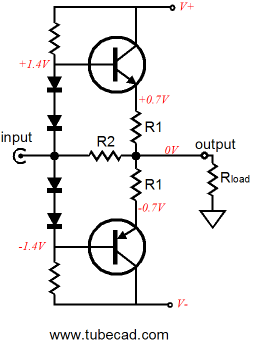
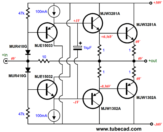
Or, we could build a simple power buffer from discrete devices, as shown below.
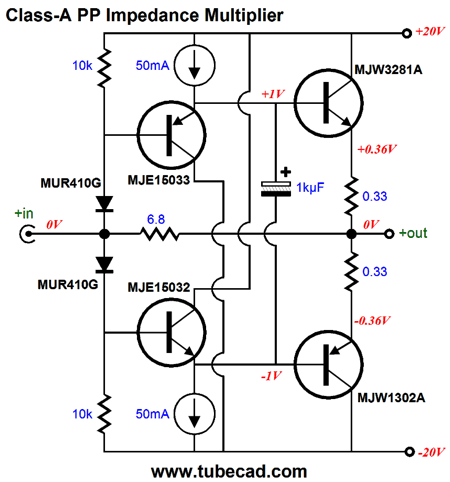
The four diodes serve as voltage references and they establish the required bias voltages for the two output transistors. Amazingly simple, don't you think? The above circuit presents a relatively low input impedance, equal to the ratio between R1/2 & R2 and the load resistance, so it could not be driven by the typical line-stage amplifier. An added complication is that this IMC must be run in strict class-A mode, as the ratio between R1/2 & R2 only holds as long as both transistors are conducting. When one transistor cuts off, the impedance ratio is halved. Class-A operation is many things: a beautifully low-distortion output, consistent output impedance for the entire output waveform, relatively easier to bias, and big, brutal, and hot. Class-A isn't for wimps. A push-pull class-A output stage must idle at half the peak output current swing (at least at half). Thus, if the push-pull class-A output stage is expected to put out a peak of 4A, its idle current must equal 2A! Think about the heat; assuming +/-40Vdc power-supply rails, one channel would dissipate 80V times 2A amount of heat, which equals 160W. Would you touch a bright 160W light bulb? No, I didn't think so, nor would I. The following is a push-pull, class-A IMC with an idle current of 1A and +/-20Vdc power-supply rails, which could deliver 16W into an 8-ohm load. Designing a simple, push-pull, class-AB, global-NFB-free IMC is difficult, but not impossible. The design problem we must overcome is that when one transistor cuts off, the impedance ratio is halved, as only one of the two R1 emitter resistors is engaged. The two R1 resistors are effectively in parallel, so when one is missing from duty, they effectively cease to be in parallel with each other. We can think of this as being the same general problem that all push-pull, class-AB output stages face, namely gm doubling (or gm halving depending on your perspective). The region of overlap between the two output devices, be they bipolar transistors or MOSFETs or tubes, will create a zone of doubled gm (transconductance), wherein the output impedance is halved. In a push-pull, class-A output stage, the full output voltage swing occurs within this zone of doubled gm. In contrast, a push-pull, class-AB output stage is not so lucky, as it encounters two big bumps, as either the top or bottom output device will cut off, leaving the work load to its active partner.
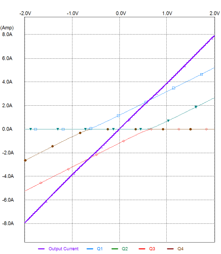
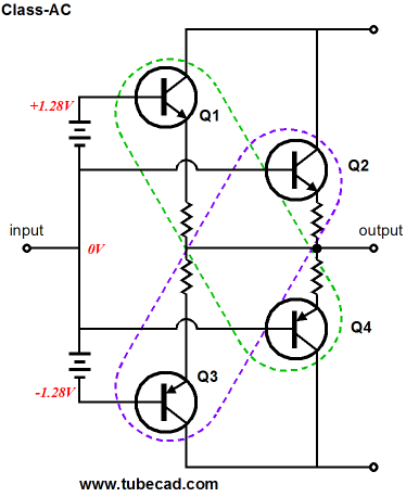
Back in blog Number 177, I described what I called class-AC, which was an attempt to overcome the problem of gm doubling.
The above graph shows how four output devices could be arranged so that a constant-gm obtains. At idle and for small voltage swings, only transistors Q1 and Q3 are conducting. Once transistor Q3 turns off, transistor Q2 begins to conduct; once transistor Q1 turns off, Q4 conducts. The result is a constant-gm output stage. Yes, it is sort of like class-A on the cheap.
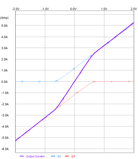
Returning to the design of a push-pull, class-AB, global-NFB-free IMC, we must anticipate that one transistor will cut off and we must come up with a means of assuring a fixed impedance ratio. The following circuit uses added two diodes and two 1-ohm resistors in the output stage to establish a fixed impedance ratio.
At idle and for small voltage swings, only the two output transistors are conducting, as insufficient anode-to-cathode voltage exists for the added diodes to conduct. But once the bottom output transistor ceases to conduct, the top added diode becomes forward biased and it begins to conduct, which means that its 1-ohm resistor enters the circuit and effectively is in parallel with the top output transistor's emitter resistor. Thus, the impedance ratio (about 18:1) remains unaltered. Instead of using the added diodes, we can use two additional output transistors, which would relieve the existing two output transistors during big output voltage swings.
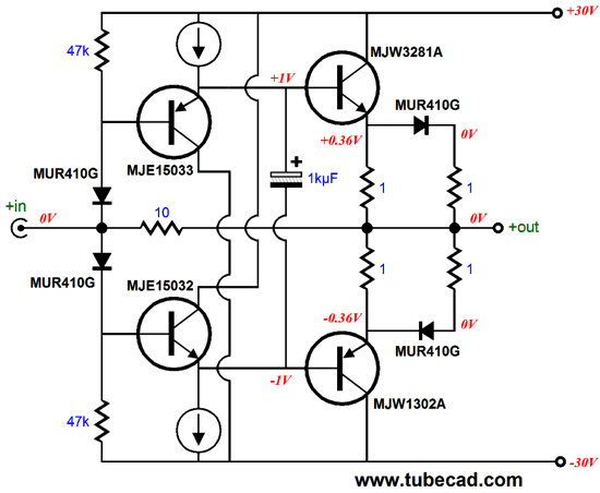
By the way, note how heavy is the idle current and note the 100mA constant-current sources. This IMC will dissipate a lot of heat, in spite of its class-AB operation. (Many solid-state output stages run an idle current of only 50mA, which is half of what the driver stage draws in this circuit.) We could back off a bit on the current draw, but I wouldn't advise it, as the thick overlap of conduction buys us lower distortion over the first—and all-important—watt of output. Putting it all together results in the following.
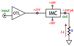
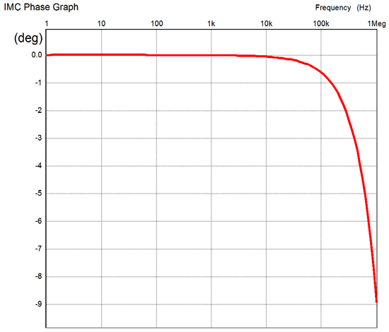
The tube-based OTL power amplifier swings up to +/-25V peaks of voltage and the IMC delivers +/-24V peaks of voltage into the 8-ohm speaker (36W). The OTL amplifier does not just drive the IMC, as it also partially drives the speaker, which it "sees" as a 150-ohm load. Note that since the IMC does not hold any global negative feedback loop, all the issues of feedback instability and phase margins simply do not apply. In fact, the IMC's phase plot is flat within 1 degree from 1Hz to 100kHz.
Next Time
* The LM12 is an obsolete device, sad to say. Nonetheless, be sure to read TI's application note, AN-446 A 150W IC Op Amp Simplifies Design of Power Circuits, as it contains some fantastically interesting material that can find application beyond the LM12's use. //JRB |
I know that some readers wish to avoid Patreon, so here is a PayPal button instead. Thanks.
John Broskie
E-mail from GlassWare Customers
High-quality, double-sided, extra thick, 2-oz traces, plated-through holes, dual sets of resistor pads and pads for two coupling capacitors. Stereo and mono, octal and 9-pin printed circuit boards available.  Aikido PCBs for as little as $24 http://glass-ware.stores.yahoo.net/
Support the Tube CAD Journal & get an extremely powerful push-pull tube-amplifier simulator for TCJ Push-Pull Calculator
TCJ PPC Version 2 Improvements Rebuilt simulation engine *User definable
Download or CD ROM For more information, please visit our Web site : To purchase, please visit our Yahoo Store: |
|||


| www.tubecad.com Copyright © 1999-2013 GlassWare All Rights Reserved |