| John Broskie's Guide to Tube Circuit Analysis & Design |
31 May 2013 Simple Phase Inverter Circuit
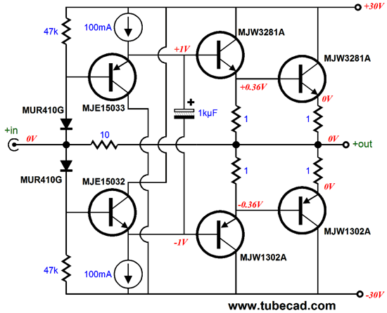
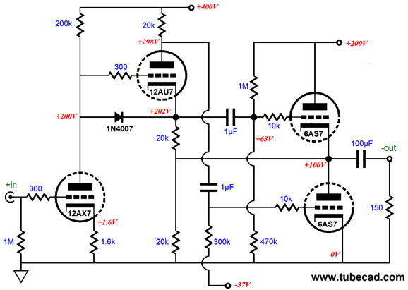
This circuit would work in parallel with the flea-power OTL design that was described in Blog Number 263.
The two circuits combine to make a 36W hybrid power amplifier, wherein the tubes share in the driving of the 8-ohm speaker, not just drive a solid-state output stage.
vs
If we want even more power delivered into the speaker, we must either build both a larger OTL and IMC (higher rail voltage at least) or go the full power-booster route:
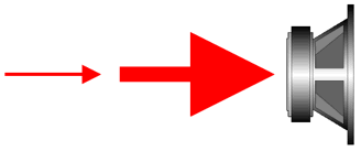
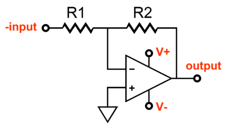
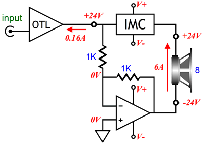
This setup requires a small external power amplifier, such as our flea-power OTL, and an IMC and an inverting power buffer, so that the speaker sees twice the voltage swing, which means it also sees four times the wattage, transforming our humble 36W rig into a mighty 144W job. The inverting power buffer must invert the small-power amplifier's output at its output. Building an inverting amplifier is easy with OpAmps, as the following is all that is required.
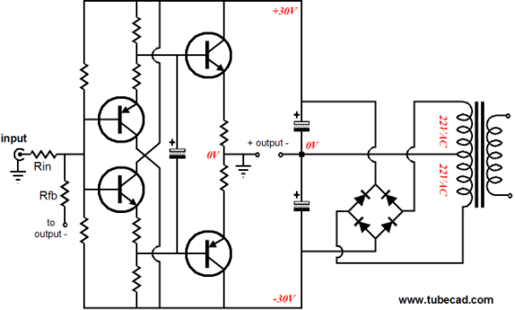
The problem with OpAmps is that few can handle a +/-30Vdc power supply and many are not unity-gain stable. An inverting buffer can be made from discrete devices, rather than with OpAmps, such as the following buffer that uses a diamond circuit with a floating power supply and and seemingly grounded output:
The negative feedback resistor Rfb attaches to the floating power supply's "ground," which is the actual output. The problem here is the floating power supply, which cannot be shared between two channels, making the power-supply design more complex and expensive. A better approach would be to build a simple inverting circuit out of discrete transistors.
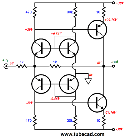
Since discrete transistors can be found with voltage ratings up to 500V for NPN transistors and -400V for PNP transistors, we can build an inverting amplifier with up to (a tad less than for safety's sake) +/-200Vdc rails. In other words, the +/-30Vdc power supply required for a 144W power booster setup is not going to be a limitation. How does this circuit work? A positive input signal will serve to turn off the input NPN transistor but further turn on the input PNP transistor, which in turn will further increase the output NPN transistor's conduction, which will pull the circuit's output down negatively by the same amount as the the input swings positively, due to the two 1k feedback resistors setting a fixed gain of -1. Transforming this circuit into an inverting power-buffer requires some burly output devices.
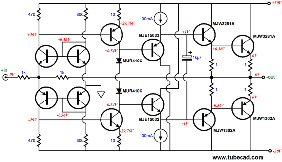
Yes, the same anti-gm-doubling ploy is used. Also note how the feedback loop extends all the way to the output. Since this inverting power buffer will effectively be working into a 4-ohm load, we could double up on output devices to better handle the increased current requirements.
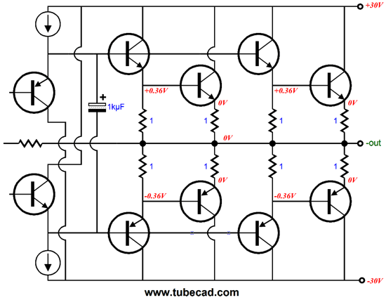
Once again, the anti-gm-doubling technique is used, with four transistors turned off at idle. By the way, the open-loop output impedance would be about 0.25 ohms; with the feedback loop in place, much less. So, if we take a step backwards, we see the following overview, with the OTL amplifier working through the IMC and the power inverting buffer creating a differential output signal for the loudspeaker.
Next Time
//JRB |
I know that some readers wish to avoid Patreon, so here is a PayPal button instead. Thanks.
John Broskie
And
High-quality, double-sided, extra thick, 2-oz traces, plated-through holes, dual sets of resistor pads and pads for two coupling capacitors. Stereo and mono, octal and 9-pin printed circuit boards available.
Designed by John Broskie & Made in USA Aikido PCBs for as little as $24 http://glass-ware.stores.yahoo.net/
The Tube CAD Journal's first companion program, TCJ Filter Design lets you design a filter or crossover (passive, OpAmp or tube) without having to check out thick textbooks from the library and without having to breakout the scientific calculator. This program's goal is to provide a quick and easy display not only of the frequency response, but also of the resistor and capacitor values for a passive and active filters and crossovers. TCJ Filter Design is easy to use, but not lightweight, holding over 60 different filter topologies and up to four filter alignments: While the program's main concern is active filters, solid-state and tube, it also does passive filters. In fact, it can be used to calculate passive crossovers for use with speakers by entering 8 ohms as the terminating resistance. Click on the image below to see the full screen capture. Tube crossovers are a major part of this program; both buffered and un-buffered tube based filters along with mono-polar and bipolar power supply topologies are covered. Available on a CD-ROM and a downloadable version (4 Megabytes). |
|||
| www.tubecad.com Copyright © 1999-2013 GlassWare All Rights Reserved |
