| John Broskie's Guide to Tube Circuit Analysis & Design |
19 April 2014
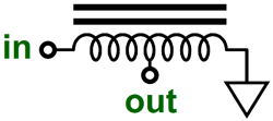
OTL power amplifiers inflame the imagination, as no other tube circuit category can match. They are by necessity massive, monolithic, macho efforts that thrill us with their potential danger of exposed high voltage and heavy current flow, for no output transformer shields us from the scary power supply, as only the glowing glass envelopes, a fragile barrier at best, dam up the lethal potential within the chassis. (This argues in favor of using a large coupling capacitor at the output, as it will protect your expensive speakers in the event of an output tube arcing or melting down into a steady short.) In addition, getting rid of the output transformer frees us from its considerable expense, weight, and squirrelly phase shifts and other nonlinearities. Negative feedback and phase shifts are incompatible. If the phase flips, what was negative feedback becomes positive feedback, a truly scary outcome. In pop-psychology terms, we all love positive feedback, as we all love praise and pats on the back. (Long, long ago, the psychological phrases "positive feedback" and "negative feedback" did not entail any evaluative payloads; rather they merely described additive and subtractive feedback in behavior-modification experiments. A subject might steadily receive an unpleasant electric shock, until he performed the desired behavior, whereupon the shock would cease, which would be an example of negative feedback, as the shock was removed. Or, he might receive an unsuspected shock, if his behavior was undesired, an example of positive feedback. Typical, of the mental morass into which the study of psychology has fallen, these definitions no longer mean much at all. Or, rather in this modern gooey quagmire of a science, they can mean whatever you want them to mean.) But in terms of electronic and mechanical systems, positive feedback usually leeds to destruction. As things go astray, they go evermore astray—until the crash. On the other hand, using an output transformer, with what would otherwise appear to be an OTL power amplifier, might be a good idea, as all the negative feedback could be kept on the OTL side and the low-winding-ratio output transformer, which would lie outside the negative-feedback loop, and would only serve to make 4-ohm and 8-ohm loads appear as 32-ohm loads. Yes, we would still incur the expense and bulk of the transformer, but we would gain more output power, less distortion, greater flexibility in speaker choice, and a lower output impedance. Here an autoformer would could be used to good effect.
Better still, an impedance-multiplier circuit (IMC), but you already knew that.
Several thoughts have come to mind, as I pondered OTL design. One was the need to reexamine a topology that I had presented ten years ago in blog number 19: the cross-coupled phase splitter within an OTL output stage.
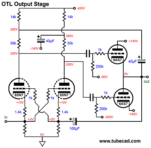
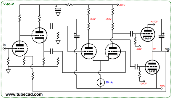
This is an interesting topology that gives us many of the same benefits as the conventional differential phase splitter would, but eliminates the need for a constant-current source or long-tailed cathode resistor. As I looked at this circuit, I wondered how it could be used with a bipolar power supply. The answer was simple enough:
Note how the garter-belt cathode bias arrangement ensures that both 6SN7 triodes more closely match each other's conduction. In addition, note how one 40µF capacitor terminates into the negative power-supply rail, which ensures that all the ripple on the negative rail will be superimposed upon the signal delivered to the bottom triode's grid, which will prevent the negative rail's ripple from being amplified. Also note how OTL output attaches at two places on the cross-coupled phase splitter. The top attachment ensures that both top and bottom output triode get the appropriate input signals from the cross-coupled phase splitter; the bottom attachment, that the cross-coupled phase splitter can receive negative feedback from the output. This negative-feedback loop would escape many a solder-slinger's perception, constituting a stealth feedback loop of sorts; all the electrical benefits without any of the audiophile guilt.
OTLs and Stealth Feedback Loops
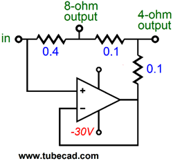
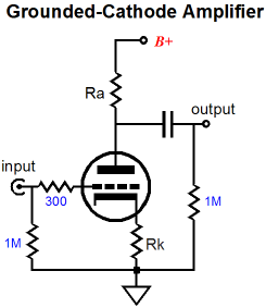
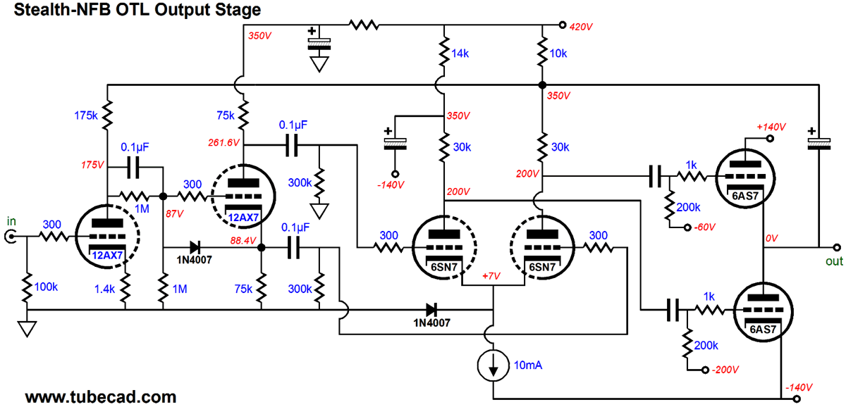
The same holds true of negative feedback; as long as a nervous audiophile doesn't know it's there, he is fine with it. How could anyone not know that a negative-feedback loop was there? Well, look at the following circuit and tell me how many negative-feedback mechanisms you count, none, one, two, or three?
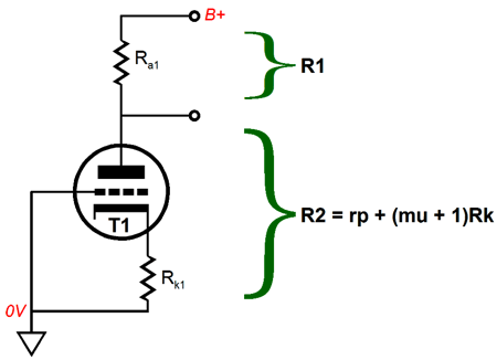
I count two. The first and largest is the unbypassed cathode resistor, which introduces degenerative negative feedback. If the signal superimposed across this resistor, as it attempts to follow the signal imposed upon the grid, fails to match that imposed upon the grid, the triode will vary its conductance of current in an effort to bring the cathode voltage inline with the grid's. Thus, the triode's transconductance fights against a disparity between grid and cathode. Since the plate resistor is in the same and only current path, the output becomes more linear with the introduction of the unbypassed cathode resistor. If this resistor were bypassed by a large capacitor, this feedback mechanism would disappear along with the reduction in distortion (but not the output impedance, which would in fact go down with a bypassed cathode resistor). The second is the the triode's plate resistance (rp), which imposes some negative feedback, as the rp opposes a change in plate voltage, conducting less or more current in response to an externally applied voltage perturbation at the circuit's output. Let's now move on to something more complex, such as the following circuit. Does it or doesn't it contain a whopping-big negative feedback loop?
The answer is that it's there all right, just hard to see. Still don't see it? Note how the capacitor that bridges the OTL's output to the differential amplifier also attaches to the input stage, but not the split-load phase splitter. This is a negative feedback loop, big whopping one at that. Yet, a disreputable, high-end-audio company could easily advertise that such an amplifier was negative-feedback-free, for who other than you (and your fellow readers) would call the company on it? Not the audio-magazine reviewers, many of whom are, in real life, lawyers and thus being professionally inured to prevarication (fibbing). To see how this negative feedback loop works imagine that a positive 1V voltage pulse is applied to the OTL's output. What happens next? In the absence of the negative feedback loop, the output triodes would provide some negative feedback all by themselves. First, the top 6AS7 triode's cathode is forced 1V more positive, thereby reducing its conduction by its amount of transconductance; in this example, by 7mA. Second, the bottom 6AS7's plate would be forced 1V more positive, which would induce a smaller decrease in its conduction; in this example, by 1/rp, or 1/280, or 3.5mA. With the negative feedback loop in place, the 1V pulse would force the right side of the differential amplifier to rise by 1V, which would cause the top 6AS7 triode's grid to rise by 1V, which would seemingly undo its 7mA decrease in conduction, as both the cathode and grid would see the same 1V pulse. But as the 1V will also travel to the input stage, there is more to the story. The input stage will halve the 1V pulse due to the input triode's rp and the plate resistor defining a two-resistor voltage divider.
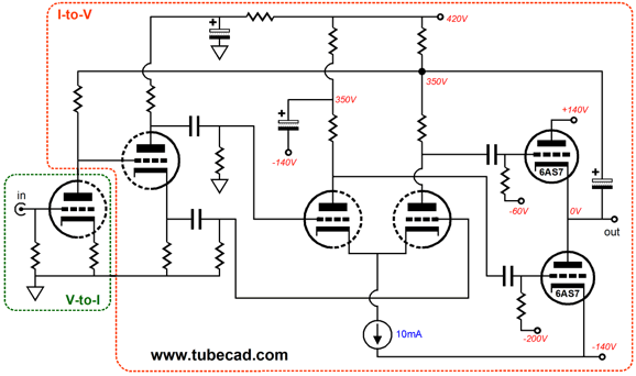
This 0.5V positive pulse will become the split-load phase splitter's input signal and both of its outputs will contain +/-0.5V pulses. In turn, the differential amplifier will amplify the pulses, which will produce a large negative voltage pulse at the top 6AS7 triode's grid and a large positive pulse at the bottom 6AS7 triode's grid. The result is that the top triode will greatly decrease in conduction, letting go of the output voltage, while the bottom triode will greatly increase in its conduction, pulling down ever harder at the output voltage, the two triodes bucking the externally imposed positive pulse thereby. What held true for the externally applied voltage pulse holds true for internally created distortion at the output. The distortion is delivered to the first stage and the OTL amplifier as a whole works to undo the distortion. Well, that was a slightly inaccurate, as the input stage actually falls out of the whole feedback loop. Indeed, we can view its plate resistor and the rest of the OTL circuit as comprising one big I-to-V converter, which converts the variation current flowing through the plate resistor into output voltage at the speaker terminal. Likewise, the input triode and its cathode resistor can be seen as being effectively a V-to-I converter that turns the variation in grid voltage into varied current flow through its plate.
If more negative feedback is needed, we could use the conventional NFB resistor that would span from OTL output to the input triode's cathode—but then we could no longer stealthily hide the feedback loop.
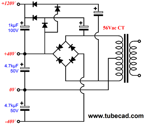
This OTL amplifier, like all the rest, defines a V-to-V converter, a voltage amplifier in other words. So, why bother pointing this out? It is useful to occasionally pause and pull back enough to see the big picture. For example, by seeing that the original stealth-feedback OTL design encompassed a V-to-I converter cascading into an I-to-V converter, we might realize that we could replace the triode-based input stage with a current-output DAC. Or, we might realize that the input stage's plate resistor could be be bypassed by a small-valued capacitor to limit the high-frequency bandwidth and improve the stability of the OTL as a whole. I cannot close on this topic without first explaining what the 1N4007 diode is doing in the stealth-feedback-OTL circuit. It is a safety device that only conducts when the OTL amplifier is turned on and the tubes are still cold. It prevents the 6SN7 triode cathodes from being 140V more negative than its grids. Once the amplifier is up and running, the diode falls out of the circuit. A second unspoken question that needs answering is what would the power supply look like for such an OTL design? Well, it needn't hold a complex power transformer with many voltage taps, as the following topology allows us to create the 420Vdc rail voltage.
In the above example, +120Vdc is created along with +/-40Vdc. By using a 200Vac CT (100V-0V-100V) secondary (and some HV rectifiers and higher voltage capacitors), we can get +420Vdc and +/-140Vdc rails.
More Thoughts on the Sandman Distortion Null Topology
The workaround that I presented was to use two power transistors to reduce the rail voltage that the error-take-off amplifier saw.
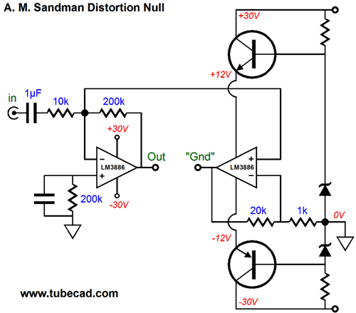
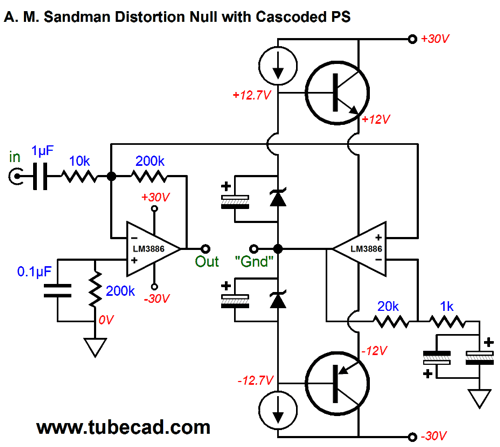
This solution would limit the heat the error-take-off amplifier would produce, but it also limited the potential power output that the two amplifiers could deliver into the speaker. Remember that the error-take-off amplifier's output voltage hovers around 0V as long as the main power amplifier does not clip. (The error-take-off amplifier's output will consist of the same amount of distortion that the main amplifier produces, which should be very small in amplitude, less than 1% of the main amplifier's output voltage swing.) But if the main amplifier clips, a form of distortion, the error-take-off amplifier's output will swing away from 0V in the opposite polarity to fill in the missing voltage. Potentially, the main amplifier's nominal power output could be quadrupled, if the error-take-off amplifier's output were allowed to swing equally large voltages as the main amplifier. The above solution will not allow that, as the +/-12V power-supply rails limit the error-take-off amplifier's potential output voltage swing to about +/-8Vpk. My new workaround is to cascode the error-take-off amplifier, so that we can both limit its heat dissipation and still allow it to swing big voltages. In the schematic below, we see the two extra power transistors no longer referenced to ground, but to the error-take-off amplifier's output. As long as the error-take-off amplifier's output voltage hovers around 0V, the two extra power transistors will also hover around their fixed output voltages. But as the error-take-off amplifier's output swings away from 0V, so too will the two extra power transistors. In other words, the error-take-off amplifier will always see a fixed 24V differential between its positive and negative power-supply pins, although its output voltage will swing up and down 24Vpk.
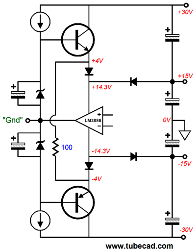
No doubt, some are scratching their heads over the two electrolytic capacitors that terminate the 1k feedback resistor on the error-take-off amplifier. Why two capacitors? Why are they placed in opposition? The assumption is that very little DC voltage will be present at the end of the 1k resistor, so a large-valued electrolytic capacitor can be used. In general, this scheme works fairly well. The problem is that, compared to film capacitors, the electrolytic capacitor produces far more distortion. One workaround is to use high-quality non-polarized electrolytic capacitors, such as those made by Panasonic, as they present far lower distortion. The other workaround is to use two normal electrolytic capacitors in parallel opposition, which tends to cancel the distortion produced by each. (I have been told that for this trick to work best, the two electrolytic capacitors should be tightly matched in value.) One important fact that must be stressed is that the universe has not been cheated. The same amount of heat will be developed within the chassis. The error-take-off amplifier has handed off some of its heat dissipation to the two power transistors, not eliminated it altogether. There are no free lunches in electronics. Not that we cannot subtract some of the excess heat by going to a class-G setup, wherein two power-supply rail voltages are used. Such an arrangement, however, gets complex and would require special power transformers.
At idle, the heat dissipation has certainly been lessened with the class-G topology. But note how the error-take-off (LM3886) amplifier now sees +/-14.3V power-supply rail voltages at idle and how more than 28.6V voltage differential across the LM3886 is now possible. For example, the negative-power-supply pin never sees less than -14.3V, just as the positive-power-supply pin never sees less than +14.3V, but both pins can see up to 28V, so maximum power-supply differential voltage would be equal to 28V + 14.3V, or 42.3V. In other words, in this class-G arrangement, the error-take-off amplifier could get hotter than it would in the cascoded version. I must also mention that while quadrupling the nominal output power is enticing, we should not forget that once we go over that nominal wattage, the 8-ohm load appears more like a 4-ohm load to each amplifier; thus, only 8-ohm speakers should be attached to this Sandman error-take-off amplifier. (If we get twice the voltage swing, we must expect twice the current flow. So, instead of 3A peak, 6A peak.) (By the way, I once received an e-mail from a reader that stated that he "mourned the demise of the once interesting articles" by me, and he was particularly saddened by those I had recently written on GainClone designs, which I seemed not to understand fully. A second later, I had shot off a reply that proclaimed that I stood chastened and I awaited links to schematics and articles written by the reader that would enlighten me as to what was truly possible—not that I could ever hope to achieve equally dizzying heights of imagination or electronic prowess, as my goal would be no more than to be humbly inspired. Well, I made the huge and shameless mistake of shooting the messenger. I failed to note the quotation marks that encompassed the entire statement and that all the text constituted a hyperlink to the original writer's missive on some forum. Well, I wonder if the above schematic would assuage some of that heartfelt mourning. Of course, it is not as transgressive, as truly unprecedented, as, say, specifying some special brand of coupling capacitors or resistors; alas, such transcendent insights elude the coarse tissue of my brain. Never forget that the architect, no matter how gifted and accomplished, is nothing compared to the interior designer who specifies lavender-colored drapes, as the latter deed requires true talent, if not genius. The architect need only know such trivial architectonic tidbits, such as structural, mechanical, electrical, materials, anti-earthquake, heating, ventilation, air conditioning, plumbing, rain gutter systems techniques and practice and a good deal of math and legal codes and many more equally easy things, whereas specifying lavender-colored drapes, rather than the fatally-wrong puce- or mauve-colored drapes, requires so much more dedication and mental wherewithal... it is no wonder that so few can perform the task ;)
Next Time
Since I am still getting e-mail asking how to buy these GlassWare software programs:
For those of you who still have old computers running Windows XP (32-bit) or any other Windows 32-bit OS, I have setup the download availability of my old old standards: Tube CAD, SE Amp CAD, and Audio Gadgets. The downloads are at the GlassWare-Yahoo store and the price is only $9.95 for each program. http://glass-ware.stores.yahoo.net/adsoffromgla.html So many have asked that I had to do it. WARNING: THESE THREE PROGRAMS WILL NOT RUN UNDER VISTA 64-Bit or WINDOWS 7 & 8 or any other 64-bit OS. One day, I do plan on remaking all of these programs into 64-bit versions, but it will be a huge ordeal, as programming requires vast chunks of noise-free time, something very rare with children running about. Ideally, I would love to come out with versions that run on iPads and Android-OS tablets.
//JRB |
I know that some readers wish to avoid Patreon, so here is a PayPal button instead. Thanks. John Broskie
Kit User Guide PDFs
And
High-quality, double-sided, extra thick, 2-oz traces, plated-through holes, dual sets of resistor pads and pads for two coupling capacitors. Stereo and mono, octal and 9-pin printed circuit boards available.
Designed by John Broskie & Made in USA Aikido PCBs for as little as $24 http://glass-ware.stores.yahoo.net/
The Tube CAD Journal's first companion program, TCJ Filter Design lets you design a filter or crossover (passive, OpAmp or tube) without having to check out thick textbooks from the library and without having to breakout the scientific calculator. This program's goal is to provide a quick and easy display not only of the frequency response, but also of the resistor and capacitor values for a passive and active filters and crossovers. TCJ Filter Design is easy to use, but not lightweight, holding over 60 different filter topologies and up to four filter alignments: While the program's main concern is active filters, solid-state and tube, it also does passive filters. In fact, it can be used to calculate passive crossovers for use with speakers by entering 8 ohms as the terminating resistance. Click on the image below to see the full screen capture.
Tube crossovers are a major part of this program; both buffered and un-buffered tube based filters along with mono-polar and bipolar power supply topologies are covered. Available on a CD-ROM and a downloadable version (4 Megabytes). |
||


| www.tubecad.com Copyright © 1999-2014 GlassWare All Rights Reserved |