| John Broskie's Guide to Tube Circuit Analysis & Design |
| 30 April 2014
This blog post is a first: it is the first one that I have ever written entirely while standing and walking. Like so many, I had been reading that sitting is worse for your health than smoking. I was spooked enough to buy a treadmill and build desk for it, so I could walk and work at the same time. How's it going? Well, my lower back isn't so happy, nor is it easy to draw schematics while standing; while walking, it's impossible. Sadly, answering e-mail has also taken a huge hit—my fingers don't seem to remember where all the keys are on the keyboard and many responses require my drawing a quick schematic. Nonetheless, I am sure that I will get better at it. Besides if this new setup helps me extend my life span by a decade, then that would be an extra decade worth of e-mail responses.
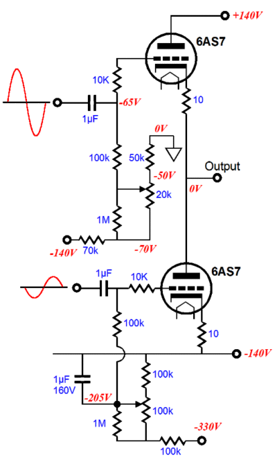
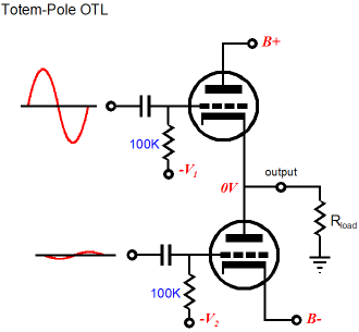
Hard-Core OTL Design Then there is the vital but often ignored problem—in a totem-pole OTL amplifier's design—of equalizing the input signals to both the top and bottom output tubes, a challenge the designer of OTL amplifiers must confront.
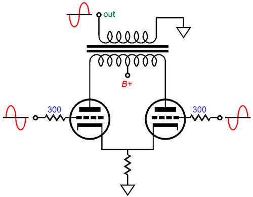
In contrast, the designer of "normal" tube-based, push-pull power amplifiers that use output transformers never deals with lopsided drive requirements, as equal, balanced drive signals are the goal, the only goal. (In part, this partially explains why the Circlotron circuit is so popular: its output tubes receive an identical, balanced input signal.) As a result, an OTL's phase splitter cannot just pass of its output signals to the to the output tubes, but must also attach to the OTL's output to establish balanced operation.
And there's the question of whether to run the OTL's output tubes as cathode followers or as grounded-cathode amplifiers, an option the typical designer of the transformer-coupled power amplifier doesn't even know exists. Much of the OTL's perceived weirdness, however, is only the result of historical accident, as transformer-coupled power amplifiers predate the OTL by many decades, so the OTL is seen as being the odd one. But if we were to strip away the familiarity, the century of past use, its wide usage, and look at the push-pull, transformer-coupled power amplifier’s inner workings with fresh eyes, we would see that it, too, is an odd bird. Don't think so? Great, draw the load-line as seen by one output tube in a class-AB transformer-coupled, push-pull power amplifier. (Hint, it is not a straight line.) While you are at it, explain what happens, when one output tube cuts off, to the half of the output transformer's primary, when it completes no current path to the ground or to any other portion of the circuit other than the B+ connection. In other words, if OTL power amplifiers had a many decade head-start, and if they were the predominate style of tube-based amplification, then I would now be explaining the perplexing inner workings of that strange push-pull, transformer-coupled, power amplifier. And many a reader would scratch his head at the weirdness of it all, longing to return to the simplicity of the “normal” OTL amplifier. (See blog number 134 for another example of it came first thus it cannot be as good, for newer is always better. Then have a piece of nutritious chocolate.) The key points to bear in mind when designing an OTL power amplifier are: 1) The load impedance counts and must be factored in the design Missing from this list was the injunction—the universal injunction against trying to cheat the laws of physics—precisely because it is a comprehensive restriction that applies to all circuit design. So, such cheats as magic zener diodes and putative class-A amplifiers that draw only a trickle of idle current are forbidden. This does not mean they we are barred from being wildly clever or making compelling new improvements, only that we must obey the strict rules of electronics. A good overview of OTL design issues is provided in blog number 121 and number 124. (As I re-read those two posts, I was struck by how good they were —something that I didn't expect. Whatever pride I might take from these posts is mitigated by my embarrassment that the first rough draft and the revised second draft and the polished final third copy are one in the same: the rough draft. Why don't I put in the extra effort? Mostly, time. If I had devoted the extra time, this would probably be only my 187th post, not my 287th. If for no other reason that each revision would have grown longer than the original.) Okay, let's say that we have obeyed all those restrictions, we are left with the problem of limited power output, whose only solution seems to be the brute-force approach: more output tubes in parallel and a bigger power supply. Because we never want the output tube grids go positive, we run into current limit that each triode can deliver into the load. The formula for a triode is: Imax = B+/(rp + Rload) Thus, for example ten 6AS7 triodes in parallel, with a cathode-to-plate voltage of 80V and 0V grid voltage, present a combined rp of about 20 ohms, so with a power-supply rail voltage of ±112V and an 8-ohm load, the maximum current flow of 112/(20 + 8) or 4A obtains, which equals 64W of average power, or 128W of peak power for the weakly honest.
Coupling-Capacitor Blocking Distortion
If the driver stage hasn't been designed in anticipation of this calamity, great gobs of distortion will arise. For example, if the grids are capacitor-coupled to the driver stage, the capacitors can become over-charged, so when the grid swings back into its negative-voltage range of operation, the coupling capacitor will present an excessively negative bias voltage; if sufficiently negative, the output tubes might cut off altogether, resulting in the infinite distortion known as “blocking,” wherein no output follows the crescendo. One workaround is to forgo the coupling capacitors, using DC-coupled cathode followers or White cathode followers to drive the grids.
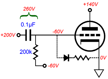
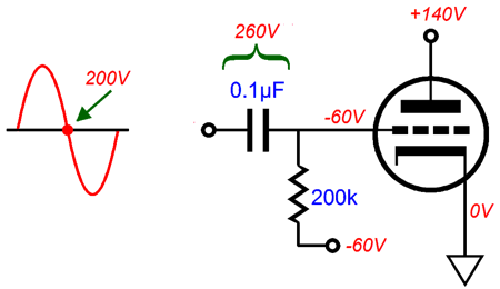
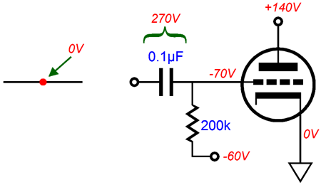
The inserted cathode follower drives the grid directly, supplying the extra current when the grid goes positive. (Note that the absolutely essential grid-stopper resistors are missing from the above schematic only because I didn't want to muddy up the big picture, but whose inclusion is just that: essential.) Another workaround to the problem of coupling capacitor blocking might be the two following circuits that I came up with long ago, but have never tested in reality. But before we look at my fixes, let's inspect the problem of a grid becoming a forward-biased rectifier. At idle, no positive grid voltage results, as the grid sits at -60V, while the cathode rests at 0V and the grid draws no current.
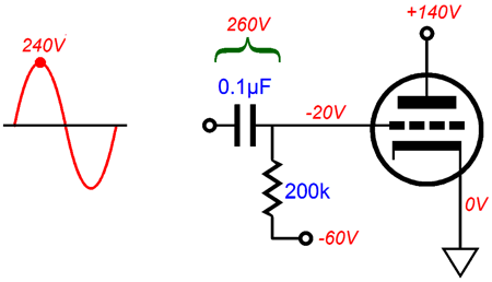
As the driver stage's output signal swings up +40 volts, the grid is still negative relative to the cathode, so no grid current occurs and the coupling capacitor still sees a voltage differential of 260Vdc. (If we could readily buy a 260V battery, we could replace the coupling capacitor with it.)
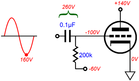
As the driver stage's output signal swings down -40 volts, the grid follows and the coupling capacitor still sees a voltage differential of 260Vdc.
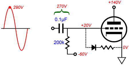
But if the driver stage's output signal swings up +90 volts, the grid becomes positive relative to the cathode, so grid current ensues, but the grid only sees 80V of the driver stage's voltage swing, as the grid's conduction drags the swing down, causing the coupling capacitor to become over charged with a voltage differential of 270Vdc.
The over-charge coupling capacitor then reduces the triode's current conduction at idle, as an extra -10V has been applied to the grid's bias voltage. As the coupling capacitor discharges, the normal -60Vdc bias voltage will be restored. In a nutshell this is blocking distortion.
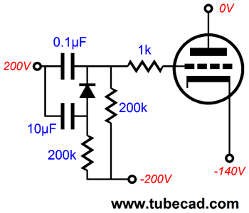
If the coupling capacitor becomes sufficiently over-charged, the output tube might cutoff altogether. (This is what happened in the early days of radar, as a too near object would produce so large a positive grid voltage that the radar screen would go black afterwards and then slowly come back to life.) Adding cathode followers that DC couples to the grids is the obvious solution, but it also brings extra cost and power-supply requirements. My first fix avoids adding the cathode follower and uses an extra coupling capacitor and a high-speed signal diode, such as the 1N4148.
In the above circuit, two coupling capacitors are used to connect to an output tube, but only one attaches to the grid directly, the 0.1µF capacitor. As long as the grid remains negative relative to its cathode, this will be the only coupling capacitor in the signal path. As the driver stage's output signal swings the grid positively, the grid-conduction current and the 0.1µF coupling capacitor voltage differential increases. But once the voltage differential grows by more than the diode's forward bias voltage, about 0.7V, the diode begins to conduct, which will place the 10µF in parallel with the 0.1µF coupling capacitor. Since the larger coupling capacitor is a hundred times larger in value, it will require hundred times more current to overcharge to the same extent that the smaller coupling capacitor would in its absence. In other words, we can expect less overcharging to occur. Once the crescendo is over and the drive signal level drops to below positive-grid territory, the smaller coupling capacitor will discharge more rapidly than the large capacitor, so the diode will quickly cease conducting, as it will no longer be forward biased. Why not just use one 10µF coupling capacitor and be done with it? Two problems: one is expense, as we could have labeled the smaller coupling capacitor as $60 and the larger capacitor as $3, the smaller coupling capacitor being a high-end, designer type, while the bigger capacitor being an off-the-shelf polypropylene-film capacitor. The second problem with using a larger coupling capacitor is that it will pass too much low-frequency signal, which can lead to motor-boating and blocking distortions due to the power-supply rail voltages varying.
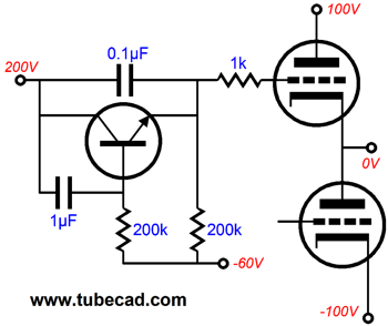
My second fix, shown above, also uses two coupling capacitors and a high-voltage NPN transistor, such as the TIP50. Once again, under normal operation, only the small-valued coupling capacitor is in the signal path. This time when a positive grid voltage causes the smaller coupling capacitor to over-charge beyond the transistor's base-to-emitter voltage drop, the transistor will start conducting, slamming the brakes on any further over-charging. Much like the my first circuit, once the crescendo is over and the drive signal level drops back into negative-grid territory, the smaller coupling capacitor will discharge more rapidly than the larger capacitor, so the transistor will stop conducting and will fall out of the circuit. (Imagine the trouble that I could cause if I were a patent attorney; instead of 287 blog posts, I would own 287 patents.) Okay, just how much more power can we expect from going into positive-grid current? The only answer possible is also the least satisfying: it depends. If the driver stage is robust enough, and if the grids do not melt, and if the cathode current does not reach its saturation point, we might easily double the power output. (For example, a single 6AS7 triode, with a cathode-to-plate voltage of 40V and +20V on its grid, will draw about 0.5A; thus, ten in parallel would draw 5A, which would equal 100W into eight ohms.) Missing from that list of “ifs” was: if the power supply voltage is big enough. Doubling the power output requires increasing the current flow—and the voltage swing—by 1.414 times. In other words, the fixed B+ voltage also imposes its own fixed limit to the OTL's maximum power output. The speaker can never see more voltage than the power supply offers.
OTL in Class-G
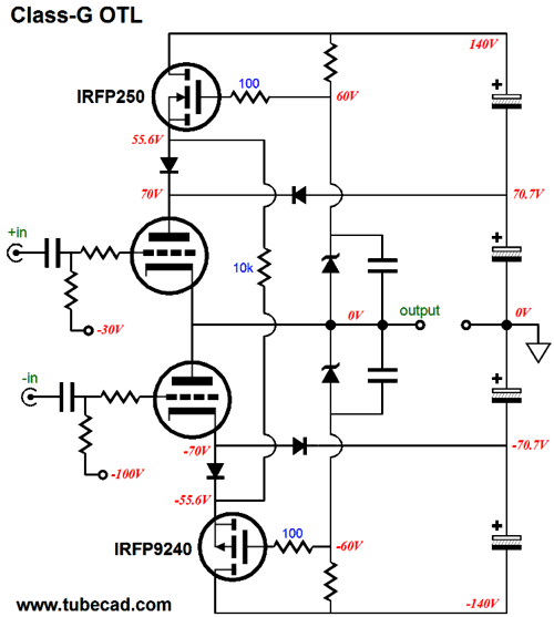
Creating a class-G totem-pole OTL is no more difficult. (Well, creating the output stage in class-G is not difficult, but creating the needed driver stage might be.)
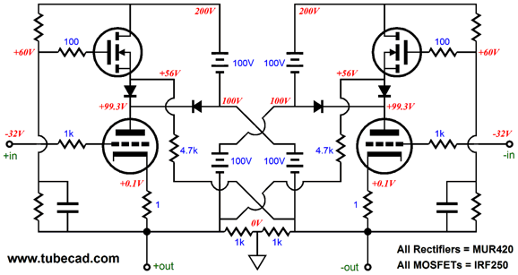
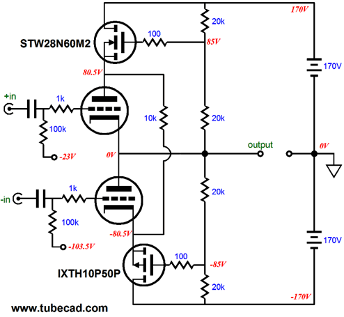
Under low-power-output operation, the two power MOSFETs fall out of the audio signal path, leaving the tube output stage only +/-70V power-supply rails. But, if it the output signal swings sufficiently up or down, say more than +/-14Vpk, the MOSFETs alternately become engaged, as the output swings positively and then negatively, allowing the OTL's power-supply rail voltages to expand with the need to deliver more power. An added advantage to this circuit is reduced dissipation at idle by the output tubes.
Normally in a totem-pole OTL, as the speaker sees more positive voltage swing, the top triode sees less cathode-to-plate voltage, while the bottom triode sees more voltage. In this class-G OTL output stage, the output tubes see a limit to how low their cathode-to-plate voltage can fall. This got me thinking that a constant cathode-to-plate voltage might work even better. Such a circuit would look something like the following.
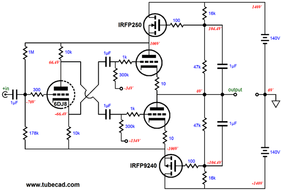
The two resistor-base voltage dividers offer a variable DC voltage division and a fixed division with AC signals. In other words, as the output swings up and down while delivering signal to a speaker, the output tubes see a fixed cathode-to-plate voltage, much as a triode would in a cascode circuit; on the other hand, if the wall voltage climbs or falls, the cathode-to-plate voltage the triodes see will also climb and fall. Yet, I prefer not to label this circuit as a cascode variation, as it would prompt agitated e-mails from many, particularly those residing in the UK, whose dedication to the purity of topological nomenclature is praiseworthy—even if taxonomically fruitless. See blog 189. (As far as most tube lovers are concerned all totem-pole arrangements of triodes, such as the White cathode follower or the Broskie cathode follower or Aikido cathode follower or cascode or SRCFPP are examples of the SRPP topology; period. For these folks, one tube atop another means SRPP; period. No doubt, they must see the Futterman OTL as just being a large example of the SRPP. And they call the cathode-coupled amplifier a grounded-grid amplifier... You try putting all the toothpaste back into the tube; I have given up on the task.) An additional advantage to the above circuit is that the output tubes effectively work under a somewhat regulated power supply, as the two power MOSFETs function as something like source-follower-based capacitance multipliers that will strip away most of the power-supply ripple at their drains from their sources. I like this circuit a great deal, as it would allow the creation of the following power buffer circuit.
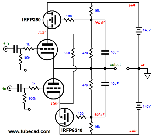
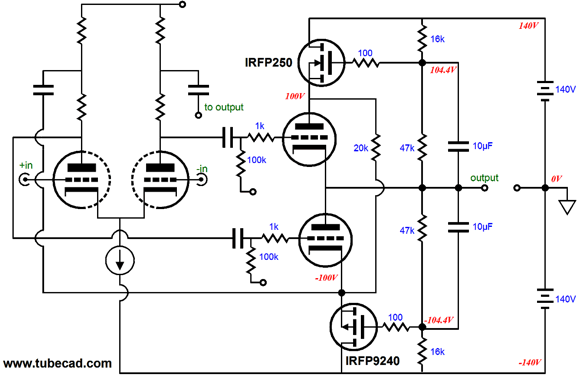
Yes, it's a head-scratcher all right. The key to making sense of it is to note that the output signal is superimposed upon both the top output triode's plate and the bottom output triode's cathode by the two MOSFETs. This signal then added and subtracted from the 6DJ8-based split-load phase splitter's output to equalize the drive signals for top and bottom triodes. Returning to the class-G OTL, the output triodes see at a varying cathode-to-plate voltage; in the above schematic, a constant cathode-to-plate voltage. Well, what if we struck a compromise wherein the cathode-to-plate voltage varied, but only half as much as it would in either the normal OTL totem-pole or the class-G OTL output stage. Such functionality is easy to implement, as the following schematic shows.
The 20k resistors define 50% voltage dividers for both DC and AC voltages. So, at idle, the triodes will see roughly 50% of the B+ voltage; and as the output swing up and down, the cathode-to-plate voltage variation will be only half of the output the speaker sees. Unlike the previous circuit, wherein the output tubes effectively work under a regulated power supply, the two power MOSFETs in this circuit only halve the ripple present on the power-supply rails, an improvement of -6dB, but still not that much. For all these variations, the following schematic shows how the driver stage attaches to the output stage.
The driver stage relays what P-channel MOSFET's source delivers to the bottom output tube's cathode to the top of the driver stage's left plate resistor, just as the output signal is relayed to the top of the right plate resistor. The result is that both output tubes sees the required signal ratio. By the way, the 20k resistor that bridges both MOSFET sources is there to ensure that the neither MOSFET ever completely cuts off.
Next Time
For those of you who still have old computers running Windows XP (32-bit) or any other Windows 32-bit OS, I have setup the download availability of my old old standards: Tube CAD, SE Amp CAD, and Audio Gadgets. The downloads are at the GlassWare-Yahoo store and the price is only $9.95 for each program. http://glass-ware.stores.yahoo.net/adsoffromgla.html So many have asked that I had to do it. WARNING: THESE THREE PROGRAMS WILL NOT RUN UNDER VISTA 64-Bit or WINDOWS 7 & 8 or any other 64-bit OS. I do plan on remaking all of these programs into 64-bit versions, but it will be a huge ordeal, as programming requires vast chunks of noise-free time, something very rare with children running about. Ideally, I would love to come out with versions that run on iPads and Android-OS tablets.
//JRB |
I know that some readers wish to avoid Patreon, so here is a PayPal button instead. Thanks. John Broskie
Kit User Guide PDFs
E-mail from GlassWare Customers
High-quality, double-sided, extra thick, 2-oz traces, plated-through holes, dual sets of resistor pads and pads for two coupling capacitors. Stereo and mono, octal and 9-pin printed circuit boards available.  Aikido PCBs for as little as $24 http://glass-ware.stores.yahoo.net/
Support the Tube CAD Journal & get an extremely powerful push-pull tube-amplifier simulator for TCJ Push-Pull Calculator
TCJ PPC Version 2 Improvements Rebuilt simulation engine *User definable
Download or CD ROM For more information, please visit our Web site : To purchase, please visit our Yahoo Store: |
|||
| www.tubecad.com Copyright © 1999-2014 GlassWare All Rights Reserved |
