| John Broskie's Guide to Tube Circuit Analysis & Design |
| 22 June 2014
Unbalanced-Input Circlotron
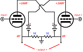
Nevertheless, while we are at it, why not continue with a Circlotron that accepts an unbalanced input signal, yet puts out a balanced output. Let's take our first baby step by quickly reviewing the Circlotron circuit.
The above circuit shows how amazingly simple the circuit Circlotron is. The two batteries are merely symbols, placeholders, for two complete floating power supplies. What is a floating power supply? It is a power supply that is not directly grounded. For example, in the above schematic, the two floating power supplies are connected to ground only through the two 1k resistors. Note how the input on the right is labeled "input +" while the one on the left is labeled "input -" which implies that a balanced pair of anti-phase input signals are required to drive the Circlotron to full output. So, how do we use only one input?
The single-ended Circlotrons shown in blog number 290 are one possibility. But these are cheats of a sort, as the real question was how do we achieve true push-pull operation of a Circlotron circuit with only a single unbalanced input signal? The answer is found in studying the SRCFPP topology, which was covered back in blog number 228.
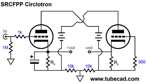
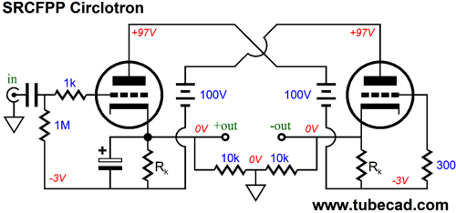
The SRCFPP (Series Reflexive Cathode Follower Push Pull) topology is very much like a White cathode follower stood on its head, as it offers class-A, push-pull operation, a near-unity gain, and low distortion and low output impedance. But unlike a White cathode follower, the sense resistor is located not at the top triode's plate, but at the bottom triode's cathode. The SRCFPP topology can be used with pentodes, FETs, MOSFETs, and transistors. In fact the math gets easier with these other devices, as none of them present the equivalent to the triode's plate resistance (rp). But let's stick to triodes first. To create a Circlotron requires one key feature: the external load must straddle ground, that the signal reference falls mid load. Sadly, about 99% of the tube-loving public falsely believe that its key feature has something to do with class-A operation. The Circlotron-class-A myth can be easily exploded by reducing the idle current on an existing Circlotron amplifier to just a few milliamperes and still obtain the same power output: no 60W class-A power power amplifier that drives 8-ohm speakers can draw only 5mA at idle; period. But where the ground is located within an amplifier is vitally important, but not easily grasped, alas. Nor is understanding how the SRCFPP easy, so by combining the two topologies into one, we will end up with a doubly-difficult circuit to understand. Fortunately, when the task requires Herculean mental effort, the mental Hercules summons the requisite effort. The following topology takes the SRCFPP and twists it into a Circlotron figure eight.
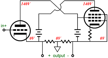
As the input signal goes positive, the left triode conducts more current, which develops a bigger voltage drop across the right triode's cathode resistor (the current-sense resistor). As this voltage grows, the right triode's cathode becomes more positive relative to its grid, or put differently, the grid becomes more negative relative to the cathode, so the right triode's current conduction falls off. Conversely, as the input signal goes negative, the left triode conducts less current, which will prompt a smaller voltage drop across the right triode's cathode resistor, so the right triode's current conduction will increase, as its grid has effectively become more positive relative to its cathode. The difference, the delta, in conduction between the two triodes is absorbed by the load. Just like a tugawar, where as one side slackens its effort, the center of the rope is pulled away, in all push-pull amplifiers amplifiers, as one side eases up its conduction, the output voltage is pulled to the side. Push-pull operation in a nutshell. What if there is no load attached, other than the two 10k resistors in series? In that case, the difference in conduction will be very small indeed. What if the output is shorted to ground? In this extreme case, the difference in conduction will be very great indeed, but the output voltage will prove microscopic indeed, as there is always some resistance, albeit very little. Still not getting it? Yes, as I warned, making sense of this circuit is not easy. The right triode's grid is "grounded" to a floating power supply, so how does the right triode get forced to conduct in anti-phase to the left triode, the triode that actually sees an input signal at its grid? The answer lies in the right triode's cathode being driven by the varying voltage developed by the varying current flowing through its cathode resistor. If the resistor is too large in value, the right triode will over react, conducting, in turns, too much current, then too little. If the resistor is too small in value, the triode will under react, failing to provide equal but opposite current swings. As you might expect there is a formula for the optimal resistor value: Rk = (rp + 2Rl) / mu where Rl is the load resistance and mu is the triode's amplification factor. This means that this Circlotron is load dependent, so one size will not fit all. In addition, unlike the conventional balanced Circlotron, which can be (and is is almost always) run under class-AB operation, the SRCFPP must be run under strict, no-advertising-copy, push-pull, honest-to-God, class-A mode, wherein the triodes each idle at half the peak out current. For example, if the goal is 5Vp into a 50-ohm load, then a peak current swing of 100mA will be needed, so an idle current of 50mA is required. Why can't we cheat like all the big boys in high-end audio and just pretend that we are running in class-A, but actually use a more forgiving and inexpensive class-AB? The answer is that the right triode cannot be driven by a left tube that is not conducting. Do not believe me? Okay, then simply remove the left triode from its socket and crank the input sign up as much as you like. Unlike chickens and politicians, which can still run without a brain, the right triode must get its input signal from the left triode. Hence, the name single-reflective, reflective as in mirrors being reflective. Lets now move on to the details. For example, the left triode got its own cathode resistor—bypassed by a large-valued capacitor—for two reasons: it allowed cathode biasing of the left triode and it created a matching DC offset to the right triode's cathode. As long as the this DC offset is identical from both outputs, the load is safe, as it sees no net DC voltage. But what is the load is a 600-ohm center-tapped signal transformer, whose center-tap is grounded? In this case, we should use the following variation.
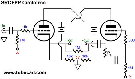
But since we are using a big capacitor in the signal path, i.e. the big-valued cathode-resistor bypass capacitor, perhaps we should just use a coupling capacitor to protect the load.
In the above schematic, we see fixed bias being used on the left triode and a combination of cathode bias and fixed bias on the right triode. In addition, a coupling capacitor protects the load, which might be expensive headphones, from sustained DC and other catastrophes. By the way, I must point out that we can achieve much the same results with a single power-supply rail, a power-supply rail that can even be shared between channels. Precisely, because we are bound to strict class-A operation, the following circuit is possible.
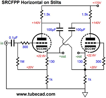
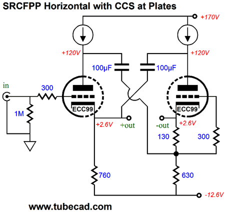
Long ago, in these pixels-laden webpages, I made a big distinction between vertical circuits and horizontal circuits, which were otherwise identical. For example, I showed how the cascode and SRPP and cathode follower could all be laid out horizontally, rather than the usual vertical arrangement. The above circuit works just the same as the vertical version with a B+ voltage of 340V; but as we never get anything for free, this horizontal version draws twice the current that the vertical version would; in sum, unity. A giant step sideways, as it were. Usually, I have used floating power supplies to perform this horizontal magic trick. Floating power supplies, however, are a pain; thus, in the above circuit, they have been replaced by large-valued capacitors.
As I look at this schematic, I realize that I should have planted an unhappy face of shame on the circuit.
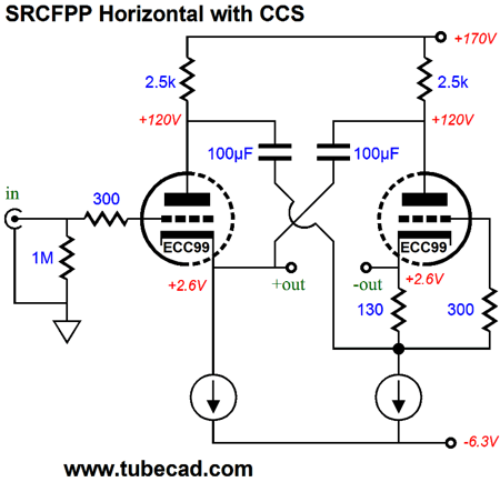
Why? The circuit does not exhibit the stellar PSRR that the 2.5k plate resistors and 100µF capacitors might seem to imply, as they do no constitute RC filters. on the other hand, if we move the constant-current sources to the plates, then we can shield the triodes from the B+ ripple. What about power-supply noise from the negative rail voltage? The assumption here was that a regulated -6.3Vdc rail would be used, so the heaters could travel along with the rest of the circuit. So how do we get to this:
I already gave away the answer, we replace the plate resistors with constant-current sources.
Note how the two CCSs force equal DC offset voltage at the two outputs, as each CCS works along a single current path to the negative rail voltage, which I bumped up to -12.6V (or is bumped down?), so that larger valued cathode resistors could be used, as these resistors are in parallel with the load being driven.
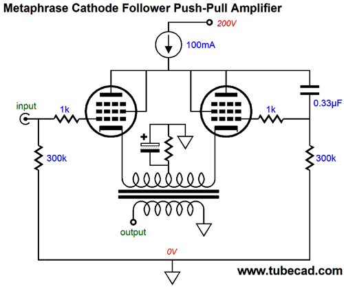
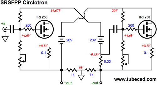
MOSFET-Based SRSFPP Circlotron
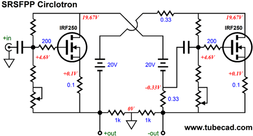
When show such a schematic, chuckle heads immediately ask, What brand of coupling capacitors would work best in this circuit? Whereupon, I despair of our hobby. The better question is, Well, John, since you refer to the 0.33-ohm resistor as all important, how was its value determined? Great question; I am glad that you asked. The formula is an easy one: Rcs = 1/gm where Rcs stands for current-sense resistor. This makes sense, as any variation in current conduction from the left MOSFET must provoke an equal but anti-phase variation in conduction in the right MOSFET. For example, say a MOSFET offers a gm of 10A per volt, then a 1/10 or 0.1-ohm RCS resistor will be needed. If the left MOSFET increases its conduction of current by 1A, the Rcs resistor will see see a +0.1V voltage drop, so the right MOSFET's source will be forced +0.1V, making its gate effectively -0.1V less positive, so -0.1V against its 10A/V gm results in a 1a decrease in current conduction. This means that this Circlotron is pretty much load independent, so one size will fit all. In other words, unlike its tube-based brothers, this SRSFPP Circlotron can work with either 4-ohm or 8-ohm or 16-ohm speakers. (Ideally, this being a true class-A amplifier, the circuit voltages and idle current would be optimized for one target load impedance.) If extra source resistors are used, as they were in this example, so as to make current measurements easier and to promote greater linearity, the formula gets expanded to: Rcs = 1/gm + Rs where Rs is the added source resistor. In order to establish greater symmetry within this Circlotron, we can place an extra 0.33-ohm resistor in series with one of the floating power supplies, as shown below.
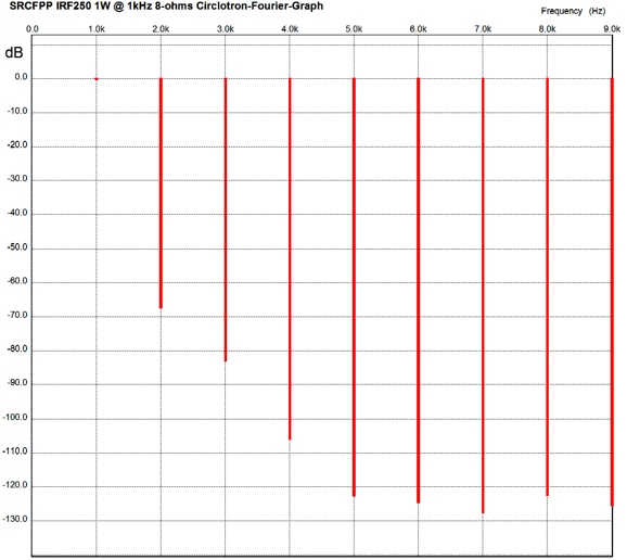
Note the balance between left and right voltage, with each MOSFET seeing the same source-to-drain voltage. So, how well does this SRSFPP Circlotron perform? Quite good indeed, as the following Fourier graph from SPICE simulations shows.
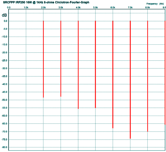
The power output was 1W into an 8-ohm load at 1kHz. By the way, this is a real average watt, not a peak watt, which many high-end-tube-audio companies have shamefully reverted to, as it makes better advertising copy. Peak watts are twice the average watt. Note the wonderful single-ended quality and the very low distortion, less than 0.1%. The gain is a tad below 2, so 8.5Vpk is needed to bring the amplifier to full output, 16W. Speaking of full output, here is the Fourier graph for 16W out.
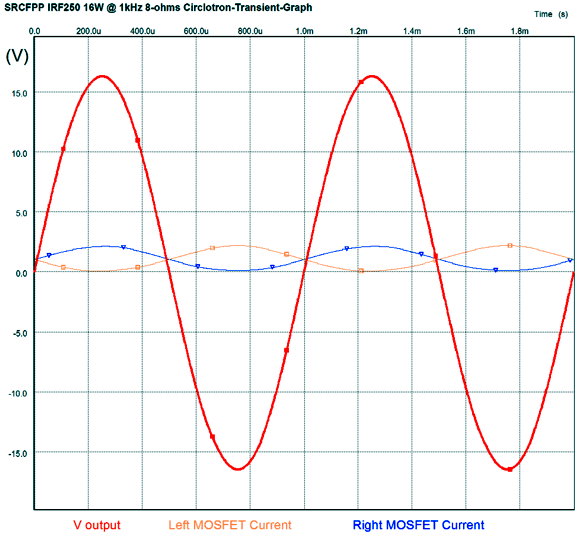
Not as lovely, but good nonetheless. How good is the push-pull current conduction? Quite good, as the following graph reveals.
An Aikido frontend would work nicely. I would use either a 6N1P or 6DJ8/6922 as the input tube and a beefy output tube, say a 12BH7 or ECC99 or 5687, run hard, say about 10mA to 15mA. Why so high an idle current? Power MOSFETs present a high input capacitance, which requires high current both to charge and to discharge rapidly.
Next Time
For those of you who still have old computers running Windows XP (32-bit) or any other Windows 32-bit OS, I have setup the download availability of my old old standards: Tube CAD, SE Amp CAD, and Audio Gadgets. The downloads are at the GlassWare-Yahoo store and the price is only $9.95 for each program. http://glass-ware.stores.yahoo.net/adsoffromgla.html So many have asked that I had to do it. WARNING: THESE THREE PROGRAMS WILL NOT RUN UNDER VISTA 64-Bit or WINDOWS 7 & 8 or any other 64-bit OS. I do plan on remaking all of these programs into 64-bit versions, but it will be a huge ordeal, as programming requires vast chunks of noise-free time, something very rare with children running about. Ideally, I would love to come out with versions that run on iPads and Android-OS tablets.
//JRB |
I know that some readers wish to avoid Patreon, so here is a PayPal button instead. Thanks. John Broskie
Kit User Guide PDFs
E-mail from GlassWare Customers
High-quality, double-sided, extra thick, 2-oz traces, plated-through holes, dual sets of resistor pads and pads for two coupling capacitors. Stereo and mono, octal and 9-pin printed circuit boards available.  Aikido PCBs for as little as $24 http://glass-ware.stores.yahoo.net/
Support the Tube CAD Journal & get an extremely powerful push-pull tube-amplifier simulator for TCJ Push-Pull Calculator
TCJ PPC Version 2 Improvements Rebuilt simulation engine *User definable
Download or CD ROM For more information, please visit our Web site : To purchase, please visit our Yahoo Store: |
|||


| www.tubecad.com Copyright © 1999-2014 GlassWare All Rights Reserved |