| John Broskie's Guide to Tube Circuit Analysis & Design |
| 28 June 2014 — 300 — Getting Close to 300 In addition, I know that this blog is different: not just due to its holding many schematics, schematics that I must draw myself; nor just due to its covering of technical topics, which often require explicating formulas; and nor is it different due to my personality leaking through. No, what makes it different is that many of the schematics only exist because I drew them, as no one else would. What brought this reflection upon me was a long-time reader commenting that he was having a difficult time catching up with my repeated postings in the month of June. He explained that he must take two to three weeks to digest fully one of my posts; and that when they come in rapid-fire succession, he loses hope of catching up. I apologized but I also revealed to him my eagerness to hit number 300, as it was so close in sight. His suggestion was that I should follow the silver rule, "one post, one topic," which would easily get me to number 300. No doubt he is right, but I am not that smart. But then, if I were smarter, I probably wouldn't post at all, as my friends and family are quick to point out that all the time and effort could otherwise be much more profitably remunerated. Fortunately, I am neither that smart nor sufficiently avaricious. The brilliant Blaise Pascal (1623–1662), in his wonderful Pensées, number 359, explains,
So, we should never fail to honor our failings. As the great Nikola Tesla put it,
FET-Triode Hybrid Bastode Line Stage Amplifier
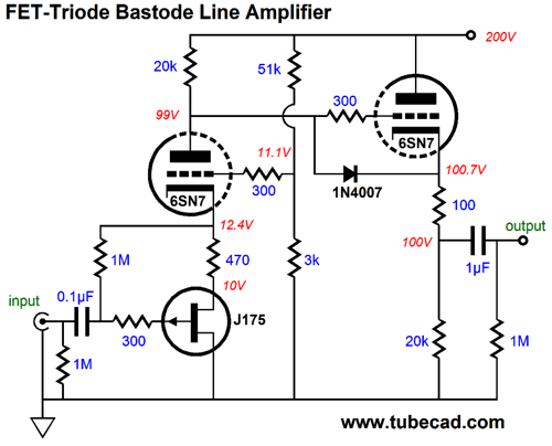
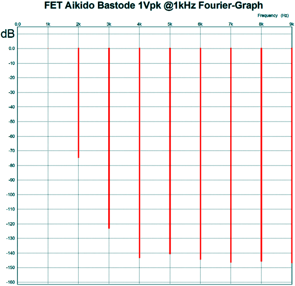
Let's start with the FET, a J175, a 30V device, which Philips describes as, a "silicon symmetrical P-channel junction FETs in a plastic TO-92 envelope and intended for application with analog switches, choppers, commutators etc." In this circuit, it is configured as a source follower, whose source drives the 6SN7's cathode through the 470-ohm source/cathode resistor. In other words, no gain from the FET, as it is the triode that delivers the gain. The FET-based source follower does not invert the signal phase, nor does the triode-based grounded-grid stage, so no phase inversion obtains. The grounded-grid's grid is grounded in a sneaky, Aikido-like fashion, which serves two purposes: the two-resistor voltage divider presents the grid with the 11Vdc bias voltage, so that the FET can operate within this DC voltage envelope created between the triode's cathode and ground; and it injects a portion of the power-supply noise into the triode's grid, so the triode can invert and amplify this signal as a grounded-cathode amplifier, thereby nulling the noise at the triode's plate. In other words, the triode functions as both a grounded-grid and a grounded-cathode amplifier. Because of the triode-based grounded-grid topology, the input capacitance is very low in this circuit, as the triode's cathode shields the FET's gate from the triodes large plate voltage swings, thereby eliminating Miller-effect capacitance multiplication. In other words, rotating the volume control will not audibly alter the high-frequency response, which a grounded-cathode amplifier, with its high Miller capacitance, would do so. What? While the volume potentiometer presents a fixed load impedance to the phono stage or CD player, it presents a varying source impedance to the line amplifier. At both extremes, it presents zero ohms, or, rather, it presents the phono stage's or CD player's output impedance at full output and zero ohms at full attenuation. At -6dB, it presents its highest output impedance, one fourth of the potentiometer's resistance; for example, 25k, with a 100k potentiometer. Now, just draw two curves from the -6dB value down to zero. Thus, you can see how the potentiometer's output resistance will define an RC low-pass filter with the input capacitance of the line amplifier. If you expect bandwidth out to at least 20kHz, then with a 100k potentiometer, the linestage's input capacitance must be less than 318pF. The second stage consists of a simple cathode follower, which both isolates the first stage from the external load impedance, a very good idea, and offers a low impedance output. Once again, this cathode follower does not invert the phase, so no net phase reversal occurs. The 1N4007 rectifier is a safety device that only conducts when the tube is cold and not conducting. Once the triodes are warm and conducting, the diode becomes reversed biased and ceases to conduct, thereby falling out of the circuit. In SPICE simulations, the circuit performed admirably, with a gain of 9.6 and an output impedance of a tad bit less than 500 ohms. The circuit's distortion harmonic structure made my eyes smile, as it presented some 2nd harmonic and little else.
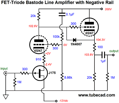
By the way, I chose the J175 only because I had a SPICE model for it. In other words, this circuit does not absolutely require it—nor the 6SN7, while we are at it. (If only I could buy a bumper sticker that proclaims, "It's the topology, stupid." But then, someone might stick an opposing sticker over it that stated, "No, it's the part brand, stupid.") Speaking of parts, FETs are not like 0.1% resistors; indeed, they are not even like 30% capacitors, as their range of acceptable IDSS is huge, crazy big. For example, the J175 span of acceptable IDSS currents is 7ma to 70mA! Yes, that is 1,000% tolerance. Of course, we can expect a bell curve of actual IDSS currents; and since the device only cost 34 cents in groups of ten, we could easily buy a fistful and and select a pair of matched FETs that worked well. If the input coupling capacitor troubles you, you can eliminate it by using a negative power-supply rail, say -12Vdc.
Note how a capacitor had to be added at the end of the two-resistor voltage divider, where it connects tot he B+ voltage. In addition, note that the source/cathode resistor is now 910-ohms in value. The result is that the gain drops to about 8 (+18dB) and the distortion falls even further. On the other hand, we could use the triode-based grounded-grid amplifier's grid as a negative feedback port:
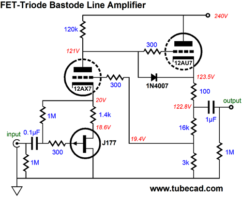
In the above variation, the assumption is that a 12DW7/7247/ECC832 would be used, with the 12AX7 triode in the first stage and its 12AU7 triode in the cathode-follower stage. The gain come in at a little over 5 (+14dB) and the distortion in SPICE simulations is very low indeed. Note the changes in resistor values and voltages; also note how the J177 replaced the J175.
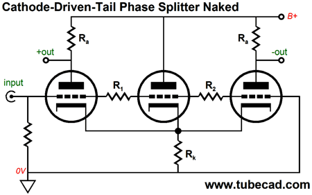
Cathode-Driven Phase Splitter
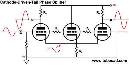
Yes, it is odd looking. Why are three triodes? What do two resistors between the grids do? Where is the constant-current source or long-tail cathode resistor? All will be answered. Let's start at the beginning, where an unbalanced input signal results in a balanced pair of output signals. That this input signal can force the leftmost triode into inverting amplification is obvious. What isn't obvious is that half of the input signal must appear at the cathode of the rightmost triode's cathode, for that triode to present an amplified and not-inverted output signal at its plate. Getting its cathode to see the required half-strength input signal is the job of the middle triode. It is given a sufficient portion of the input signal to prompt its cathode to pull along the right triode's cathode into alignment. Thus, the two resistors, R1 & R2, in between the grids.
If the center triode exhibited infinite transconductance, then resistors R1 and R2 would share the same value. With real triodes, resistor R1 will always be lower in value than resistor R2. Here is a fleshed–out example.
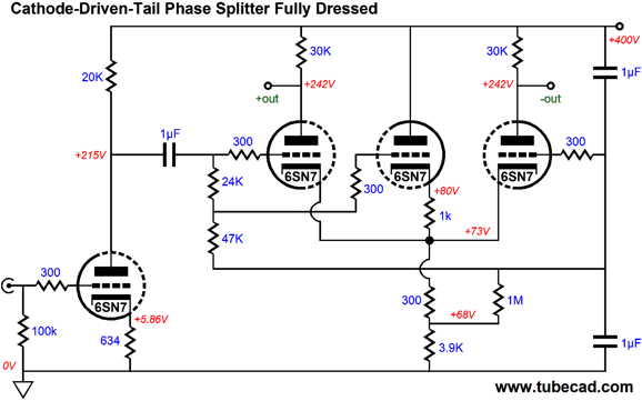
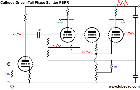
Here our old friend the 6SN7 helps us achieve two goals: great balance and stellar PSRR. The input stage is a simple grounded-cathode amplifier, which provides a gain of about 10. It also leaks about 50% of the power-supply noise at its output. The two-resistor voltage divider appears in between the grids, providing the center triode with its input signal. The center triode's 1k cathode resistor limits it current conduction; and the 300-ohm cathode resistor below it sets the 68Vdc bias voltage for all three phase splitter triodes. The 3.9k cathode resistor was chosen to result in a power-supply noise null at the two outputs, which was also helped by the two 1µF capacitor in series, which define a 50% AC voltage divider. These capacitors also provide a 0.5µF shunting capacitance for the B+. Since the two plate resistors are in the same current path as the 3.9k cathode resistor, a variation in current flow through the 3.9k resistor will also create a varying current flow through the center triode and the two 30k plate resistors. If we skillfully select the right values, the left and right triode plates will pull down by the exact same amount as the B+ voltage rises, resulting no change in plate voltage, and, thus, no power-supply noise at the two outputs.
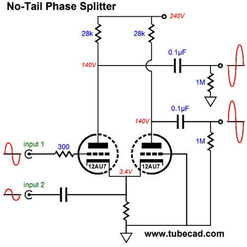
By the way, if you are feeling that odd déjà vu sensation, it is due to this phase splitter being inspired by the no-tail phase splitter from blog 294.
But rather than using two triodes and two input signals, this new phase splitter design uses one input signal and three triodes.
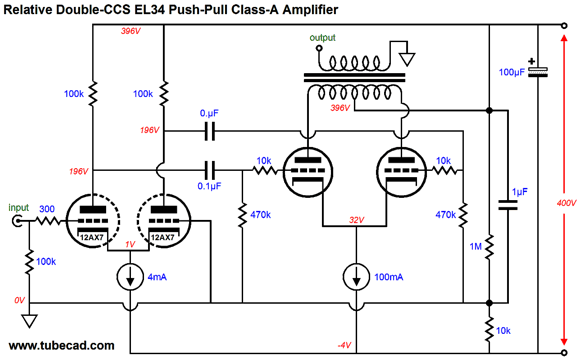
Constant-Current Sources and Push-Pull Amplifiers As always is the case, a few more thousand words could have been summoned to explain this circuits functioning, advantages, and liabilities. For example, many liabilities were sidestepped by using the EL84 output tubes, as these little marvels exhibit many fine qualities, such as requiring a low cathode-to-grid biasing voltage and relatively small input voltage swings. These advantages allowed us to get away with a 12AU7-based input stage and an LM317-based constant-current source. Other output tubes would not be so amenable, requiring both greater cathode-bias voltage and input signal swings. For example, the 6L6 or 300B would prevent the use of the 12AU7, as it could not deliver sufficient gain, while the LM317's 37V voltage limit would prevent its safe use in the constant-current source. The two workarounds would be to use a 12AX7 in place of the 12AU7, and an LM317-HV in place of the plain LM317. (Actually, with 300B output tubes, even the 57V voltage limit for the LM317-HV would likely prove insufficient, so a TL783, with its 125V voltage limit would be a better choice.) Although the 12AX7 offers much higher gain, it also brings a new problem, too little cathode-to-grid voltage for most solid-state constant-current source to operate within. For example, with a cathode-to-plate voltage of 200V and 2mA idle current, the 12AX7's cathode needs to be only 1V more positive than the grid. The famous LM334 CCS requires at least 1V to work, which the long-tailed phase splitter will not grant, as the 1V cathode voltage will fall to 0.5V with a 1Vpk input signal. What to do? There are several possibilities, but I favor the following.
This design is an old one, as I built up a Dynaco Stereo-70 along these lines back in the 1980s. I had run right into the LM334's minimum-voltage limit and I didn't want to use the negative-bias voltage rail within the amplifier, as it used a half-wave rectifier circuit, which provoked a unilateral current draw within the power transformer, which worked to magnetize the transformer core—besides, this negative rail provided too much negative voltage, which would exceed the LM334's maximum voltage limit. One workaround that I thought of was to add a -12V power supply to the amplifier, which would power the two 12AX7 heaters and the two LM334s. But there was no room under the ST-70's chassis. I was about to give up, when it hit me that I could place the ground elsewhere, thereby creating a new negative voltage rail. What? You cannot do that! This is one of those intellectual blind-spots that I encounter often. For 99.9% of solder-slingers, ground is not negotiable; it is where it is because it must be there; period. For me, ground is only a circuit's voltage reference and its placement is entirely within my whim and fancy. In the above circuit, ground is located between the 1M and 10k resistors. (In my actual ST-70, I was only able to perform this radical shifting of ground due to my not using the existing power-supply capacitors; instead, I used two computer-grade electrolytic capacitors. The original ST-70 capacitors hard-wired the ground to the capacitor case and the chassis.) Constant-current sources can do wonders for eliminating power-supply noise. And since both the input and output stages used constant-current sources, it would be tragic not to get a fine PSRR out the power amplifier. Thus, the 1µF capacitor that shunts the 1M resistor. It couples the ground to the B+, so all the power-supply noise appears at the bottom of the 10k resistor and the -4V power-supply rail voltage, from which the two constant-current source shield the cathodes. I must mention that while this amplifier sounded just fabulous, it did not put output much wattage. Why not? For starters, it runs in strict class-A, so the idle current through each output tube equals half of the peak current draw per output tube. Never forget that a class-A power amplifier maximum theoretical efficiency, whether the amplifier is single-ended or push-pull in design, is only 50%. And, in reality, with vacuum tubes and DCR-laden output transformers, expect only 30% max. Second, the output stage runs the EL34 output tubes in triode-connected mode, which limits the potential plate-voltage swings, thereby limiting potential power even further. In other words, the modified ST-70 put out only 5W per channel. We can do some quick math. The output stage's constant-current source's idle current squared against the plate-to-plate output transformer primary impedance divided by four gives us the maximum theoretical peak output power; in this case, 100mA² x 4300/4 = 10.75Wpk, which equals, in RMS terms, 5.375W. If we want more power, then we must either bump up the constant-current source's idle current or use more output tubes. By the way, I was recently told that you could get 60W of class-A power from a pair of KT88 output tubes. Really? Let's do the math and assume that the KT88 exhibits an rp of zero ohms (when I give a handicap, I give a big handicap). Okay, since the theoretical maximum efficiency of a push-pull, class-A output stage is 50%, an output power of 60W implies a dissipation of 120W at idle, which means that each KT88 must dissipate 60W, 20W beyond its 40W limit. Now, let's allow some more reality to creep into the math, such as positive-grid limits, plate resistance, output transformer DC resistances and core losses... A quick mental calculation results in about 25W to 30W, if we run the poor tubes at their limits.
User Guides for GlassWare Software
Next Time
For those of you who still have old computers running Windows XP (32-bit) or any other Windows 32-bit OS, I have setup the download availability of my old old standards: Tube CAD, SE Amp CAD, and Audio Gadgets. The downloads are at the GlassWare-Yahoo store and the price is only $9.95 for each program. http://glass-ware.stores.yahoo.net/adsoffromgla.html So many have asked that I had to do it. WARNING: THESE THREE PROGRAMS WILL NOT RUN UNDER VISTA 64-Bit or WINDOWS 7 & 8 or any other 64-bit OS. I do plan on remaking all of these programs into 64-bit versions, but it will be a huge ordeal, as programming requires vast chunks of noise-free time, something very rare with children running about. Ideally, I would love to come out with versions that run on iPads and Android-OS tablets.
//JRB |
I know that some readers wish to avoid Patreon, so here is a PayPal button instead. Thanks. John Broskie
Kit User Guide PDFs
E-mail from GlassWare Customers
High-quality, double-sided, extra thick, 2-oz traces, plated-through holes, dual sets of resistor pads and pads for two coupling capacitors. Stereo and mono, octal and 9-pin printed circuit boards available.  Aikido PCBs for as little as $24 http://glass-ware.stores.yahoo.net/
Support the Tube CAD Journal & get an extremely powerful push-pull tube-amplifier simulator for TCJ Push-Pull Calculator
TCJ PPC Version 2 Improvements Rebuilt simulation engine *User definable
Download or CD ROM For more information, please visit our Web site : To purchase, please visit our Yahoo Store: |
|||


| www.tubecad.com Copyright © 1999-2014 GlassWare All Rights Reserved |