| John Broskie's Guide to Tube Circuit Analysis & Design |
21 November 2015
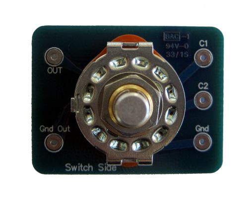
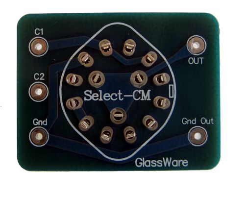
New GlassWare Product: the Select-CM
I just mentioned mono-bloc power amplifiers. Why? I love having an input mute switch on my own amplifiers, as I like to be able to change interconnects without having to shut-down the amplifiers first. Well, I also like having an option on the input coupling capacitor, assuming there is one. Why? My present single-ended power amplifiers hold an input coupling capacitor that imposes a high-pass filter at 100Hz, as I use powered subwoofers with my satellite speakers. But if I bring my amplifiers over to a friend's house or choose to use them with a full-range speaker in my own house, I have to short the input capacitor out first. Well, by adding a Select-CM, I would only need to turn a knob and a larger-valued coupling capacitor would be used, restoring the full low-frequency bandwidth to the amplifier. Many readers live in apartments or in a house shared with others, such as spouse and kids, which means that late-night or early-morning listening is out, due to the excessive low-frequency rumblings. Well, by switching to a smaller-valued coupling capacitor you would limit the low-bass frequency response of the amplifier, allowing your neighbors some quiet sleep. Of course, most will buy the Select-CM to use in a dual-mono line stage system. By the way, the Aikido noval mono PCBs are back in stock. Almost all of the GlassWare line stage PCBs hold dual output coupling capacitors, which allows you the ability to chose the sonic overlay that the music being played requires. For example, the coupling capacitor that sound just fabulous with a recording of a lone blues singer playing the harmonica might make recording of a dense orchestral performance sound clouded and blurred. Of course, a different coupling capacitor might invert these outcomes. The Select-CM's last position, where both capacitors are in parallel, is fun, as you can hear the blending of two radically different sounding coupling capacitors, such as PIO in parallel with polypropylene film. The result often sounds much different and better than either alone. The new GlassWare Select-CM switch kit is only $18 USD and is available now at the GlassWare-Yahoo store. It includes the PCB and rotary switch. Amazingly inexpensive and amazingly effective.
Even More
Even More Constant-gm Output Stages
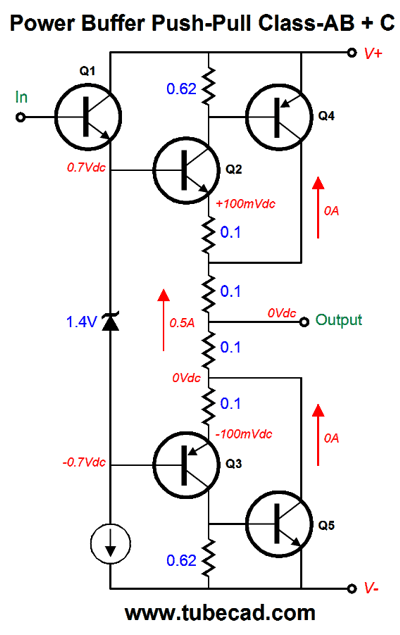
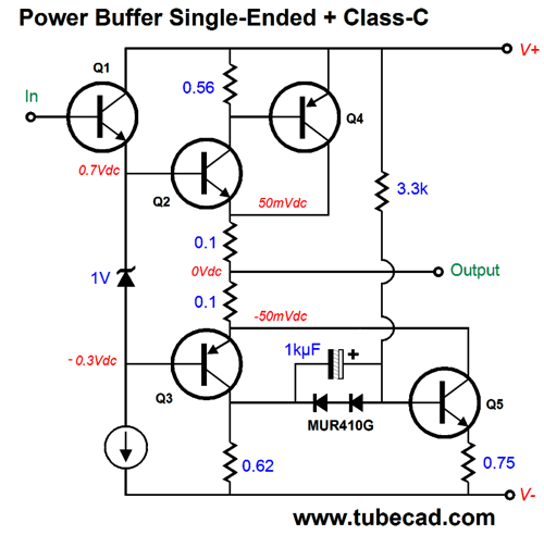
Output transistors Q2, Q3, Q4, and Q5 do the heavy lifting; but at idle, transistors Q4 and Q5 are completely cutoff, as the idle current flowing through Q2 and Q3 is insufficient to create enough voltage drop across the 0.62-ohm collector resistors to turn on Q4 and Q5. Once the positive output current into the load equals twice the idle current, transistor Q3 also turns off and Q4 begins to conduct, effectively shunting the topmost 0.1 emitter resistor. The result is that the output stage's gm remains constant, as does the output impedance. (At idle the output impedance—without any help from a global negative feedback loop—is about 0.1 ohms; at full output, it is also about 0.1 ohms.) Transistors Q4 and Q5 cannot run wild, as they are under the control of transistors Q2 and Q3. We can exploit this setup by using lateral MOSFETs, which cost a bundle, and with bipolar power transistors, which cost about $1 each. Now, that we have done our mental stretching, we move on to something new. We begin with the bridged (or differential-output) amplifier, which are common in car stereos and in class-D designs.
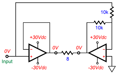
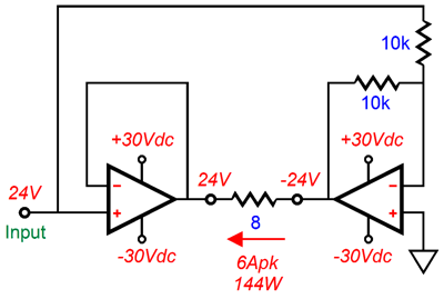
The two anti-phase power amplifiers allow twice the voltage and current swings that a single amplifier would achieve with the same rail voltages and load impedance.
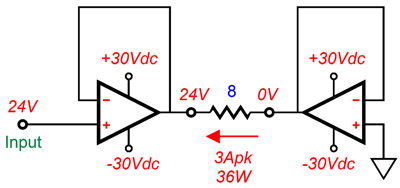
Normally, a single power amplifier running with +/-30Vdc power-supply rails would deliver at least 36W into an 8-ohm load. But the bridge amplifier, working with the same power supply voltages and load impedance, could deliver 144W. How is that possible? Where the single amplifier could only swing 24Vpk and 3Apk into the 8-ohm load, the bridge amplifier delivers 48Vpk and 6Apk into the same load. (The assumption here is that the power supply and output stages are robust enough to deliver twice the current flow.) As far as each individual power amplifier is concerned in the bridge amplifier, the load it is driving is 4-ohms, not 8 ohms. Think about it: 24V divided by 6A equals a resistance of 4 ohms, not 8 ohms. Imagine that we break the differential aspect of the bridge amplifier, so that the right amplifier functions as a virtual ground, due to its ignoring the input signal that the left amplifier receives.
Now, we get only 36W of output and the left amplifier sees an 8-ohm load. Wonderful, John, but what does this have to do with constant-gm output stages? Once again, I have taken the indirect route, so please bear with me. One thought I had was that since the load impedance is effectively doubled in the class-A region of the output stage's operation, what if we could effectively halve the load impedance in the class-A range and then restore its full value as the output stage entered class-B operation? Would this not effectively achieve a constant-gm output? Interesting possibility, no? But how to proceed? Here is what I came up with.
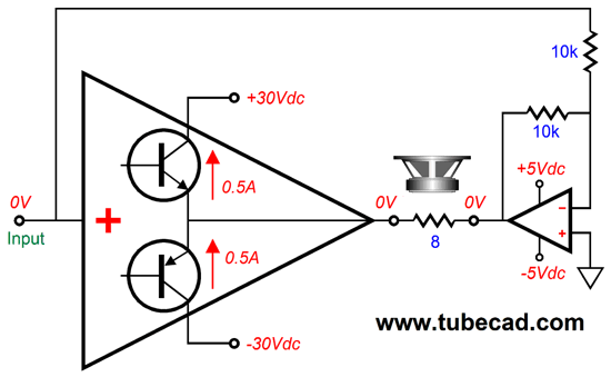
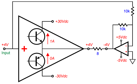
The idea shown above is that two power amplifiers are configured in a bridge topology, with both idling at 500mA, but using different power-supply-rail voltages. The amplifier on the left gets +/-30Vdc rails, while the one on the right only gets +/-5Vdc rails. As you would expect, the amplifier on the left can swing much larger output voltages. Let's assume that each amplifier can swing its output voltage to within a volt of its rail voltages, so the left amplifier can swing +/-29Vpk, while the right amplifier can swing +/-4Vpk. What happens when the right amplifier clips? The right amplifier's output will flat line at either +4V or -4V, which is what we want it to do.
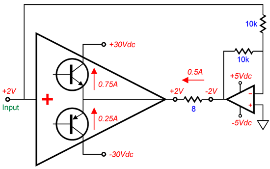
In the above illustration, we see both left and right amplifiers swinging 2V, so the load sees a voltage differential of 4V, which implies a current flow of 500mA. Now, as far as the left amplifier is concerned, the load impedance must be 4 ohms, as 2V/0.5A equals 4 ohms. But as both output transistors within the left amplifier are still conducting, each output transistor "thinks" it is driving an 8-ohm load, as the top output transistor's conduction only went up by 250mA from its 500mA idle current, but the output went up by 2V, which implies an 8-ohm load, as 2V/250mA equals 8 ohms. This effective doubling of the load impedance holds true right up to the point where one output transistor ceases to conduct.
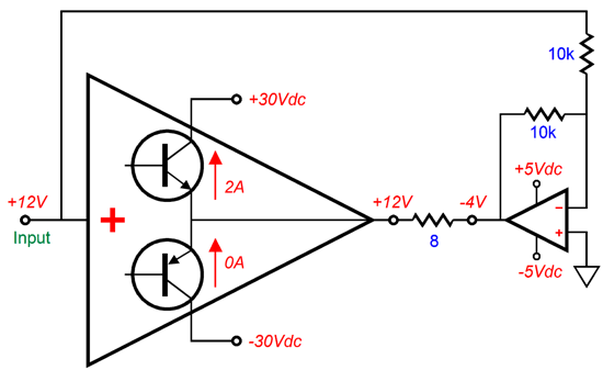
Once we move into class-B operation, the right amplifier's output sticks to a steady 4V. In the example below, we see that top output transistor's current conduction has doubled from 1A to 2A and the output has climbed by 8V to 12V, which implies an 8-ohm load, as 8V/1A equals 8-ohms.
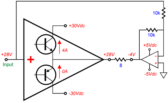
At full output, the 8-ohm load sees a voltage differential of 32Vpk, which implies an output wattage of 64W, as shown below.
Thus, as far as each output transistor in the left amplifier is concerned, the load impedance has remained a constant 8-ohms. Okay, so how good is my idea? First, the right amplifier must exhibit a cleanly clipped output, not one filled with overshoots or oscillations. Indeed, it would probably be best to pre-clip the right amplifier's input signal, so the amplifier actually wouldn't clip, although its output looked clipped.
Second, if loudspeakers presented a flat impedance, this scheme just might work. Alas, excepting some planer speakers, they don't. In order for this scheme to work with all speakers, the transition to flat line output from the right amplifier cannot be fixed, but must dynamically follow the shifting impedance. Can this be done? It might, if the transition was set by the actual turning off of one of the output transistors within the left amplifier.
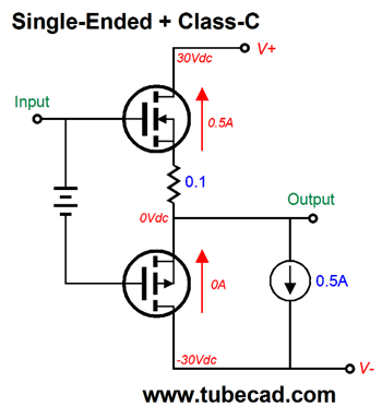
Single-Ended and Class-C
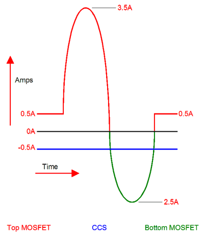
At idle, the P-channel MOSFET is completely cutoff and does not begin to conduct until the output swings below -4Vpk. The constant-current source conducts a steady 500mA throughout the output waveform and at idle. So, in order to get 36W and 3A of peak current swing into an 8-ohm load, the following current relationships would obtain.
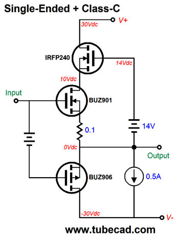
An idle current of 500mA against the 60V of power-supply voltage implies a dissipation of 30W, which is plenty hot, but not nearly as hot as a pure 36W single-ended amplifier would run, as a 36W single-ended amplifier like the one above would require an idle current of 3A, six times more than 500mA, which means six times more heat dissipation. The great thing about class-C is the zero heat dissipation at idle, which is great for the P-channel MOSFET, but the top N-channel MOSFET doesn't get a break. My next step was to add a second N-channel MOSFET in cascode.
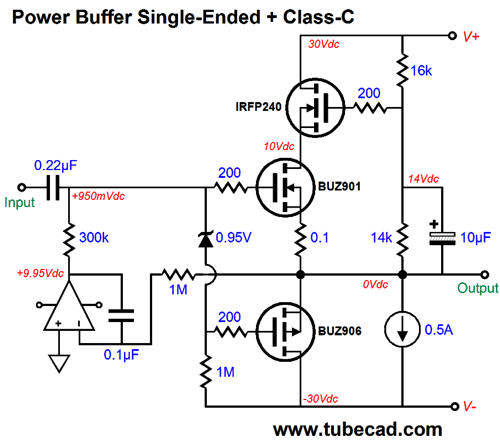
Now, the cheaper IRFP240 must dissipate most of the heat, with the expensive BUZ901 dissipating half as much heat as the IRFP240, while the BUZ906 dissipates no heat at idle, as it is cut off. The next idea I had was that we could easily add a DC servo loop to eliminate any DC offset.
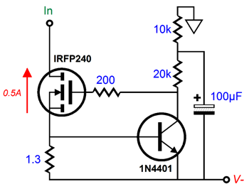
How would the constant-current source be implemented? We could use a circuit like this:
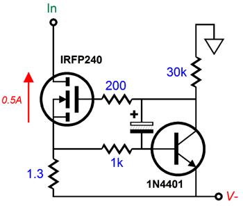
Or, we could use the following design.
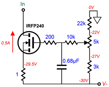
Or, for those who love potentiometers, we could use the following design.
But the more I thought about it, the less that I liked any of these constant-current-source designs. Not that there is anything wrong with them. No, it was just that I wondered if the constant-current source couldn't be asked to do more work. Here is what I came up with: a nearly constant-current source or, rather, a threshold constant-current source. In other words, a constant-current source that drew a steady current flow up until it was forced to break from its fixed current flow, allowing it to flow at a greater current, but never a flow below its fixed value. Here is how I implemented it:
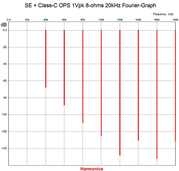
Please excuse the switch to bipolar output devices and the elimination of the cascoding, but you still get the idea: at idle, transistor Q5 sees a fixed base voltage and it behaves like a constant-current source. But once transistor Q3 draws more than 1A of current, Q5 begins to increase its conduction. I ran some SPICE simulations on this output stage and the results are interesting. Here is the Fourier graph for 1Vpk of output at 20kHz, not 1kHz, into an 8-ohm load.
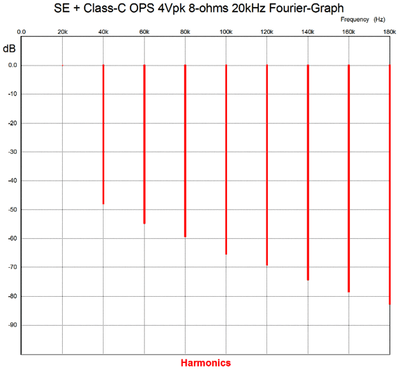
Very single-ended. The THD comes in below 0.1%. Next, we see the graph for 4Vpk, which equals 1W into 8 ohms.
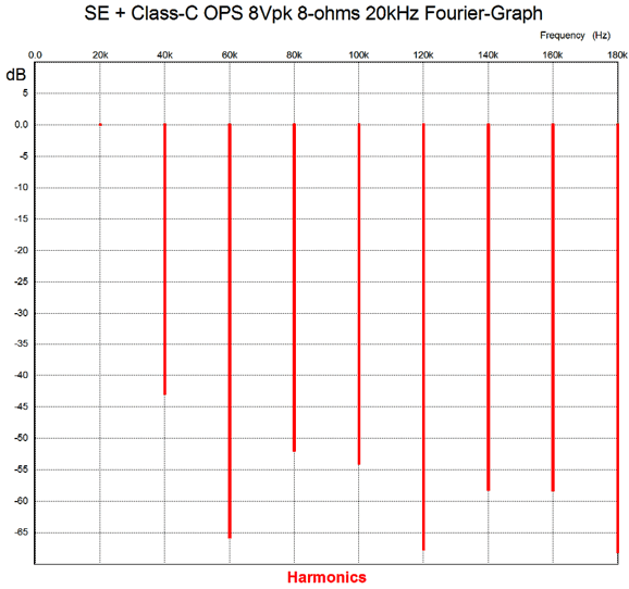
Still wonderfully single-ended in structure. Next, we see the graph for 8Vpk, which equals 4W of output.
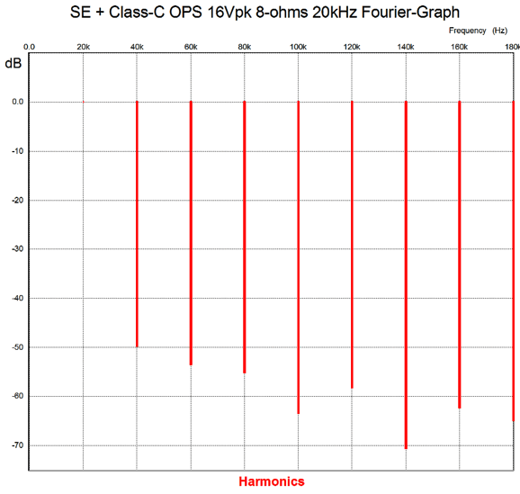
Note the amazing reduction of the 3rd and 6th harmonics. Next, we see the graph for 16Vpk, which equals 16W of output.
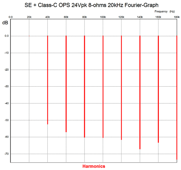
This also looks fine, as the nasty 5th and 7th harmonics are nicely subdued. Finally, we see the graph for full output, i.e. 24Vpk, which equals 36W of output.
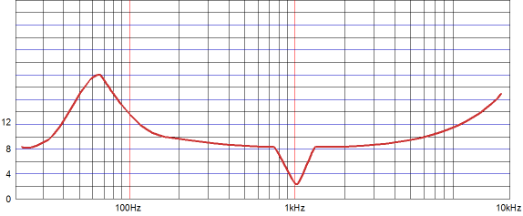
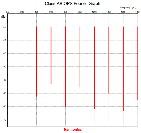
Not bad, not at all. It still retains a strong single-ended structure. If the output stage had used the devices and worked into the same load impedance, but was configured as a classic class-AB output stage, what would the Fourier graph look like? I couldn't easily convert this circuit into class-AB output stage, but I know from examining hundreds of Fourier graphs what it would look like; something like the following.
This is the shape we see with all push-pull, class-AB output stages, whether they are tube-based or solid-state-based, transformer-coupled or OTL. The even-order harmonics are reduced below the odd harmonics, creating the familiar, but not ear-pleasing, saw-tooth shape.
Next Time
User Guides for GlassWare Software Since I am still getting e-mail asking how to buy these GlassWare software programs:
For those of you who still have old computers running Windows XP (32-bit) or any other Windows 32-bit OS, I have setup the download availability of my old old standards: Tube CAD, SE Amp CAD, and Audio Gadgets. The downloads are at the GlassWare-Yahoo store and the price is only $9.95 for each program. http://glass-ware.stores.yahoo.net/adsoffromgla.html So many have asked that I had to do it. WARNING: THESE THREE PROGRAMS WILL NOT RUN UNDER VISTA 64-Bit or WINDOWS 7 & 8 or any other 64-bit OS. One day, I do plan on remaking all of these programs into 64-bit versions, but it will be a huge ordeal, as programming requires vast chunks of noise-free time, something very rare with children running about. Ideally, I would love to come out with versions that run on iPads and Android-OS tablets.
//JRB |
Kit User Guide PDFs
And
High-quality, double-sided, extra thick, 2-oz traces, plated-through holes, dual sets of resistor pads and pads for two coupling capacitors. Stereo and mono, octal and 9-pin printed circuit boards available.
Designed by John Broskie & Made in USA Aikido PCBs for as little as $24 http://glass-ware.stores.yahoo.net/
The Tube CAD Journal's first companion program, TCJ Filter Design lets you design a filter or crossover (passive, OpAmp or tube) without having to check out thick textbooks from the library and without having to breakout the scientific calculator. This program's goal is to provide a quick and easy display not only of the frequency response, but also of the resistor and capacitor values for a passive and active filters and crossovers. TCJ Filter Design is easy to use, but not lightweight, holding over 60 different filter topologies and up to four filter alignments: While the program's main concern is active filters, solid-state and tube, it also does passive filters. In fact, it can be used to calculate passive crossovers for use with speakers by entering 8 ohms as the terminating resistance. Click on the image below to see the full screen capture.
Tube crossovers are a major part of this program; both buffered and un-buffered tube based filters along with mono-polar and bipolar power supply topologies are covered. Available on a CD-ROM and a downloadable version (4 Megabytes). |
||


| www.tubecad.com Copyright © 1999-2015 GlassWare All Rights Reserved |