| John Broskie's Guide to Tube Circuit Analysis & Design |
|
26 August 2016
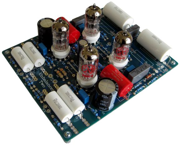
New: Unbalancer Two
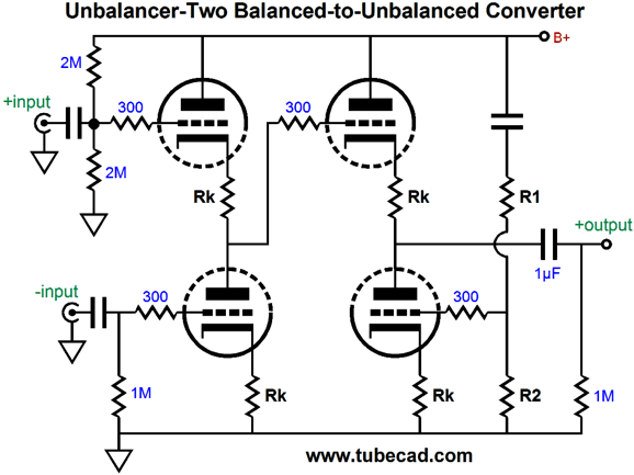
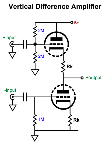
The Unbalancer Two's low gain makes it much closer to the signal transformer. In fact, much like a 1:1 signal transformer, the Unbalancer Two can also accept an unbalanced input signal at either its inverting or its non-inverting input. Of course, the inverting input will invert the input signal at its output, while the non-inverting input won't. (In fact, the Unbalancer Two can accept an unbalanced signal, at either input, as long as the other input is grounded, making the Unbalancer Two a low-gain line-stage amplifier, which a phase switch would allow easy phase reversals.) The Unbalancer-Two circuit deconstructs into a vertical differential amplifier whose output feeds an Aikido cathode follower.
The vertical differential amplifier works by presenting the top and bottom grid with a pair of input signals equal in amplitude, but inverted in phase relative to the other. This arrangement results in one triode drawing greater current and the other less current, which results in the nexus, the connection, between top and bottom triodes to move either up or down with the balanced input signal. Ideally, such an arrangement would yield a signal gain of 2 (+6dB), as the absolute amplitudes of both balanced signals would sum. With real tubes, however, we get slightly less than a gain of 2 (about 1:1.7 or +4.6dB with most tubes).
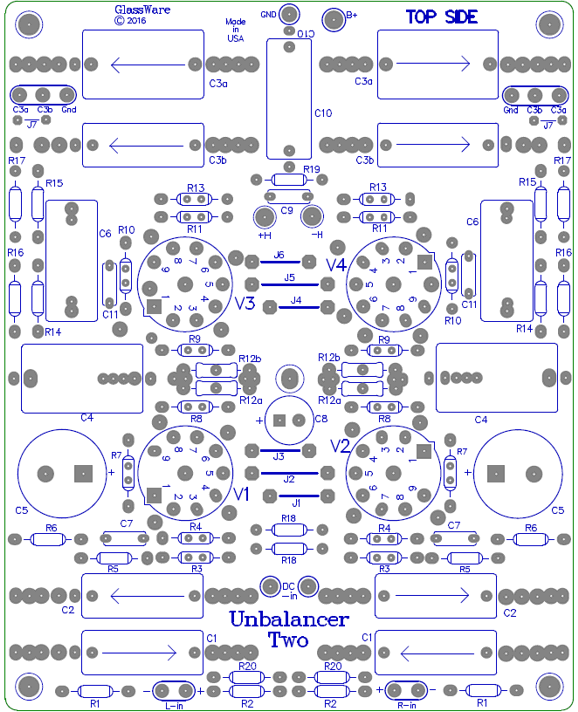
On the other hand, a common-mode signal presented to both top and bottom triodes results in an in-phase variation in current flowing through both triodes, which will result in a tie, much like two exactly equally strong men arm wrestling, so the differential stage's output remains flat, as the two in-phase current variations null. Hence, the name “Differential Amplifier,” as the circuit passes the differences in balanced signals and largely ignores what is common to both signals. The effectiveness of a differential amplifier at rejecting common signals to both inputs is denoted by CMRR, which stands for common-mode rejection ratio. With well-matched triodes and tight-tolerance resistors, a CMRR of -60dB can be achieved. The Unbalancer-Two's output stage is an Aikido cathode follower, which not only delivers low-distortion and low output impedance, but also scrubs away power-supply noise from the output signal. The Unbalancer PCB requires two external power supplies, one for the high-voltage B+ and a low-voltage regulated power supply for the heaters. The high-voltage power supply can be unregulated, as the PCB holds an RC B+ filter in both channels to smooth away ripple. The 12AX7 & 12AU7 and 6DJ8 & 6DJ8 pairing of tubes work quite well in the Unbalancer. The 6DJ8 pairing allows using a relatively low B+ voltage of only 150Vdc, whereas the 12AX7 & 12AU7 pairing is much happier with 240V to 300Vdc. Of course, many other dual-triode tubes could be used, such as the 6N1P or 12AT7 or ECC99.
The Unbalancer Two kits are now available at the GlassWare store.
Unbalancer Two Uses
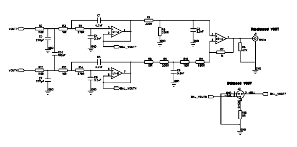
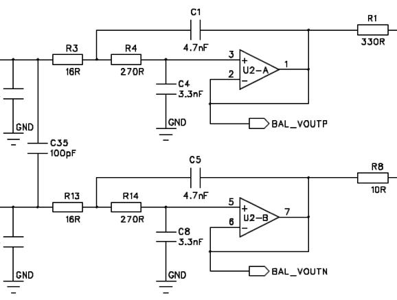
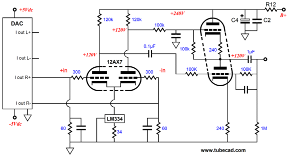
Since this schematic is tiny and blurry, here is a closeup.
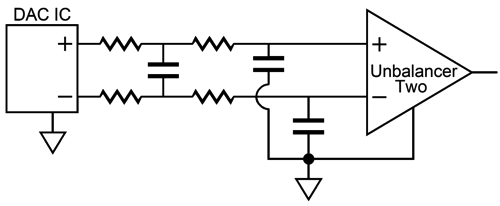
If you plan on tapping directly off the DAC IC itself, prior to any solid-state post filtering and buffering, then using a simple two-pole balanced low-pass filter might be needed. (Since both inputs on the Unbalancer Two are capacitor coupled, we need not worry about any DC offset leaving the DAC IC.)
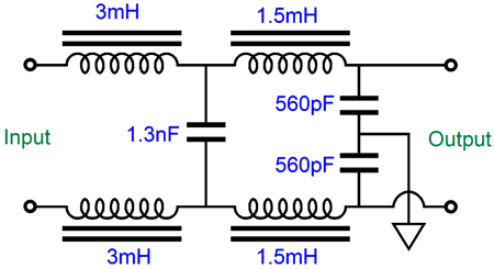
If steeper filtering is required, then the resistors could be replaced by inductors. The following 4th-order low-pass filter is down -6dB at 100kHz and is down -80dB at 1MHz (the filter alignment is Linkwitz-Riley, i.e. cascaded Butterworth, with a Q of 0.5, i.e. the result of two 0.707 Q 2nd-order filters cascaded.)
Resistors R1 & R2 on the Unbalancer Two's PCB should be 1k in value for this filter.
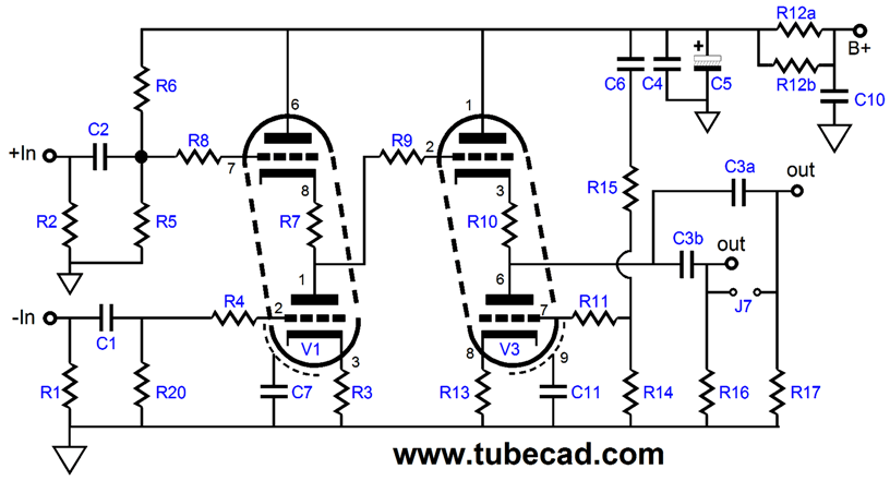
On the other hand, if the DAC IC puts out a balanced current-output, then resistors R1 & R2 can be used as I-to-V converters. Bear in mind that since the Unbalancer Two offers very low signal gain, slightly less than +6dB, a better choice might be the original Unbalancer circuit, shown below, which offers a gain much closer to +20dB (or more, with a high-mu input tube, such as the 6N1P or 12AX7).
In the above schematic, the original Unbalancer is called upon to deliver a lot of gain, as the 60-ohm I-to-V resistors yield a small input signal for the Unbalancer. Then there is the third case, wherein the DAC puts out a blend of current and voltage. My understanding is that the famous ESS Sabre DAC is such a type and that it can be terminated by much larger I-to-V resistors, which means very little gain is required, making the Unbalancer Two a more suitable match.
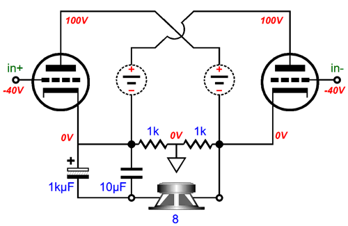
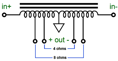
Circlotron Odds and Ends Let's assume a B+ voltage of 100Vdc and an idle current of 80mA per triode. Eight 6AS7 tubes means 16 triodes, eight per bank, so a combined idle current of 0.64A and a total plate dissipation of 128W. So, what would be your quick guess? Remember that the theoretical limit to efficiency for any push-pull class-A power amplifier is 50%, so we know that the output can never exceed 64W. The answer is found by doubling the idle current, then squaring the sum and multiplying the product by half of the load impedance; namely, (2 x 0.64)² x 8/2, or 6.55W. So, my guess was a tad pessimistic. Mind you, 6.55W is the maximum amount of class-A watts into an 8-ohm load. So, how close did we get to 50% efficiency? Not very, as 6.55W/128W equals 5.11%. Such a Circlotron amplifier, however, can deliver many more class-AB watts, say about 32W. (More class-AB watts would be possible, if a higher B+ voltage was used or if we were willing to drive the 6AS7 grid positively relative to the cathodes, thereby risk blocking distortion.) If the load impedance had been 32 ohms, however, then the math would reveal 26.2W of class-A output, bring the efficiency up to about 20%, with about 45W of class-AB watts possible. How do I know this last figure? The math is simple" Ipk = Vb / (rp +Rload) W = Ipk² x Rload/2 where rp equals the plate resistance; Vb, the B+ voltage; Ipk, the peak output current swing; and Rload, the load impedance. Eight 6AS7 triodes in parallel effectively present very low plate resistance, as each triode presents an rp of about 220 ohms at its 0V-grid line. (The data sheets and tube manuals say 280 ohms, but that is more in the middle of the plate curves.) Now, 220/8 equals 27.5, which plugged in the formulas yields: Ipk = 100V /(27.5ohms + 32ohms) W = 1.68A² x 32ohms/2 = 45.2W We see that the 32-ohm load is a much better match for the output tubes than an 8-ohm load, we can get almost five times more class-A power. Well, why don't we give this Circlotron a 32-ohm load? You could, if you are handy at building speakers, as two 16-ohm drivers or four 8-ohm drivers could be put in series. A better solution would be to use an autoformer (i.e. autotransformer), as it would allow us to drive existing 8 and 4 ohm speakers.
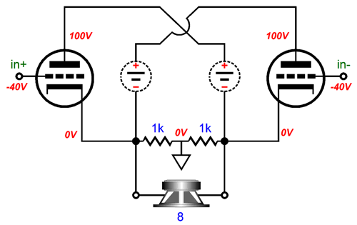
Last time I made this suggestion, a reader wrote me proclaiming that a normal audio transformer would prove far safer. Interesting. His fear was that an autoformer could not protect the speaker should an output tube arc or should one high-voltage power supply fail, while the other remained energized. Before evaluating the autoformer's safety, let's review a plain-Jane Circlotron.
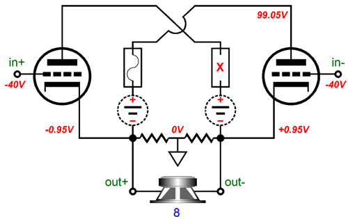
No current flows through the speaker at idle, as no voltage potential exists across its leads. All is safe. Imagine that you worry about the 100V floating power supplies, so you place a fuse in series with each, as shown below. Much safer, you might imagine. Is it?
The speaker leads get twisted and end up shorting briefly. Brief as the short was it was long enough to blow one of the fuses. Now the Circlotron presents a DC offset of 1.95Vdc. Not good, but the speaker will not catch on fire. On the other hand, if my preferred approach to biasing the output tubes is used instead, wherein rather than use a single negative -bias-voltage power supply that is grounded, we use two floating negative -bias-voltage power supplies in a garter-belt bias scheme, which tends to auto-correct DC offsets, the engaged tube see a slightly lower bias voltage and only 1.66Vdc develops across the speaker terminals.
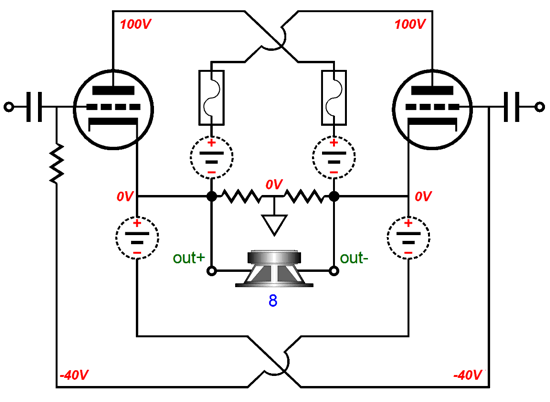
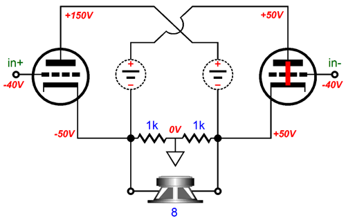
What happens if one of the output tubes arcs? If you have never seen this happen, count yourself lucky. If the fuses are in place, we end up with the previous situation, as one fuse will certainly blow. Without the fuses, the situation is far worse. Thus, the answer tot he my last question, "is it," is yes, it's much safer with fuses.
Until it melts, the speaker's voicecoil will get hotter than your toaster over, as 1,250W of heat will develop out of it. Once melted, the speaker can become a dead short, so the insulation on the speaker cables will melt and your carpet will catch fire. Not good. If the Circlotron amplifier holds a slow-blow fuse in series with its power cord, maybe you might only lose your speaker. Maybe much more. How can we change the ending of this electronic horror story? We could add a new character, a coupling capacitor. The famous Futterman OTL power amplifiers used huge coupling capacitors, which kept the speakers safe, even from an arc in an output tube.
I know how audiophiles think—God save me—and many are disheartened by the inclusion of huge coupling capacitors. They wonder, "What is the point of an OTL if it contains huge coupling capacitors?" Well, the Futtermans all held huge coupling capacitors and they sounded fine. In addition, we could get away with using high-quality non-polarized coupling capacitors, particularly those made by Panasonic, as they sound far better than the typical, polarized electrolytic coupling capacitor. And since no DC offset exists at idle, we could probably get away with using 16V non-polarized coupling capacitors. (Twenty 100µF non-polarized coupling capacitors in parallel would allow low-end extension down to 10Hz and would present very little ESL, effective series inductance.) One quality film or PIO bypass capacitor (or two) wouldn't hurt. Amazingly cheap, yet amazingly effective.
Another approach would be to use an autoformer, as it would not only protect the speaker, but it would also yield higher output power and far lower distortion and output impedance from the output tubes. How would an autoformer protect the speaker? Remember that it is only a long length of solid-core wire wrapped around a ferric core. Its DCR (direct-current resistance) is low, very low, say 0.4 ohms. Its inductance presents a higher impedance at frequencies above 20Hz; but at DC, the the impedance equals the DCR. Should one floating power supply's fuse blow, the speaker will only see a DC offset voltage of about 10mV. Perfectly safe. Even if an output tube melts down and becomes a dead short, the world is not lost, as the fuse and the low-DCR will save the day. Most of the current will flow through the 0.4-ohm autoformer wire instead of the speaker's 8-ohm impedance before the fuse blows. The speaker will still experience one huge jolt, before the DC state establishes itself, so you might still blow a driver or two in your speaker. An output transformer would be a bit safer, as no DC offset could occur on its secondary. Don't forget that an output transformer will also transfer brief current surges, just no steady current flow. What about brief tube arcs and autoformers? Use fuses on the floating power supplies. An output transformer's biggest advantage is that high-quality output transformers are made and their relatively high winding ratios allow us to use far more linear output tubes than the 6AS7. (Just because it looks something like a 2A3 does not mean it is as linear.)
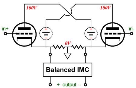
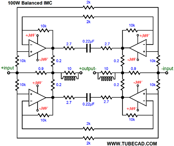
(Forgive the return of the battery symbol in place of the floating power supply symbol, as the schematic is an old one.) A 300B-based transformer-coupled Circlotron would offer both low distortion and low output impedance. One problem we would face is that each bank of output tubes would need its own separate heater power supply. Because a 2A3 or 300B or triode-connected KT88 require much higher B+ voltages, albeit at a much lower current, we could use tube rectifiers instead of solid-state devices. (Imagine an amplifier chassis sporting four KT88 output tubes and two tube rectifiers and one output and two power transformers.) In addition, this Circlotron would require huge balanced input signal swings. (Mind you, so does a 6AS7-based Circlotron. It's just the 300B will require a bit larger swings.) Moving to a new topic, rather than use an autoformer, which are rare and expensive, we could run the Circlotron's output tubes in pure, honest-to-God, push-pull, class-A mode, if we presented it with a high enough load impedance by using an impedance-multiplier circuit (IMC). An IMC would make the 4- and 8-ohm speaker appear as a much high impedance. How high? Let's do the math. We want to get 100W output of the eight 6AS7 output tubes, but not let them leave the class-A window of operation. First we must find the peak voltage output swing required to develop 100W into an 8-ohm load. The formula is: Vpk = √(2W x R) Plugging in 8 ohms and 100W results in 40Vpk. Next we divide twice the idle current into 40V. Assuming each triode idles at 80mA and eight triodes per bank, we divide 40V by 1.28A, which equals 31.25 ohms. Dang close to 32 ohms, so we will round up to that value. Thus, the balanced IMC must make the speaker's impedance seem like 32 ohms to the Circlotron by adding 3.75A of peak current tot he Circlotron's 1.25A.
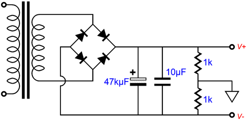
Much of how to make this setup happen was covered back in blog post 281, so I won't repeat myself anymore than I have to. In that post, I pointed out that the solid-state IMC did not have to be powered by a bipolar power supply, as mono-polar one would work just as well, if not better. I showed the following simple power supply and I pointed out how two could be made with one toroid transformer.
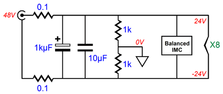
If we made the power supply's output voltage equal to 48V, the IMC could easily deliver 40Vpk swings and we could place all eight 6AS7 heater elements in series across the 48V, thereby getting a DC heater power supply. Since we can readily buy 48V switcher power supplies, why not use one instead?
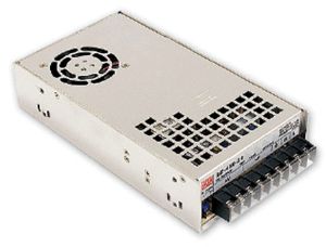
The 0.1-ohm resistors and 1kµF capacitor help filter away the harsh high-frequency harmonics from the switcher power supply. As drawn, it looks as if a wallwart or desktop switcher would be used. Actually, I was thinking more along the lines of an internal, encased switcher, such as the Mean Well SE-450-48, which Jameco sells for $63.
This unit puts out up to 9.8A (451W), which is far more than we would need with 8-ohm speakers (including the heater load of 2.5A), but is only a tad more than is needed for 100W into 4-ohm speakers. Note that the switcher current is set in stone, unlike a conventional power supply.
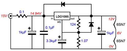
I get many emails complaining that a 12Vdc @ 1A switcher wallwart power supply will not power two 6SN7 heaters in series, which only draws 600mA. What gives? The math states that 6.3V divided by 0.6A equals 10.5 ohms of resistance. But if you actually measure the DCR of a cold 6SN7 heater element, you discover that it is only 1.5 ohms in resistance. Once hot, the heater's resistance climbs to 10.5 ohms. The problem is that the switcher power supply shuts down once more than 1A of current flow is experienced. Since the heater never gets hot, its resistance remains too low for the switcher. The workaround is to either use a 12V @ 4A switcher or place an inductor or thermistor in series with the heater string with the 12V @ 1A switcher or place a 4.7-ohm power resistor in series with the heater string with the 15V @ 2A switcher. Another possibility is to use a linear regulator after a 15V switcher, as shown below.
The input 0.1-ohm series resistor and 1kµF input capacitor help a bit, but the real hero is the 3.3kµF electrolytic capacitor, as its slow charge up gives the 6SN7 heaters a chance to slowly warm up. By the way, soft starts, like this one, greatly prolong tube life. Another two possibilities are the following.
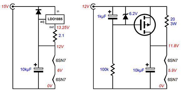
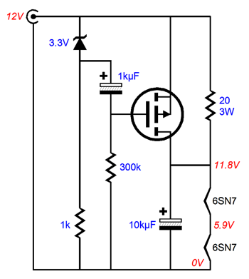
The circuit on the left uses a 15Vdc @ 1A switcher and LD1085 configured as a constant-current source. Because the LD1085 limits the current flow to 600mA, the switcher never complains. The circuit on the right uses a P-channel power MOSFET to impose a slow start. In fact, this circuit offers two stages of slow start, as the 20-ohm resistor allows current to flow into the heater string, while the MOSFET not yet turned on. Once on, the MOSFET shunts 20-ohm resistor, so 11.8Vdc appears at the top of the heater string. (The MOSFET could be replaced by a power bipolar transistor, with some fiddling of part values.) Another variation on this theme would be the following, which uses the same parts, but differently arranged. The result is a shorter transition from one mode to the other and about 30 seconds of slow warm up time.
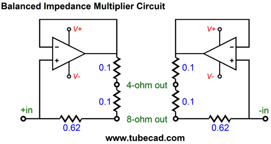
With the 2.5A heater string draw from the eight 6AS7 output tubes, something similar might be needed, say a 100W, 20-ohm series resistor with the heater string, which is shunted by a relay once the heaters warm up a bit. Or, perhaps, a rotary switch that made five steps to full heater voltage. In short, switcher power supplies are not the easy slam dunk that many imagine them to be. Returning to power output into 4-ohm loads. Normally, with a solid, i.e. robust, solid-state power amplifier, the power out into 4-ohm loads is double what it is into 8-ohm loads, as the amplifier is fundamentally voltage-limited. But the strictly current-limited switcher power supply imposes an output power limit similar to a 100W audio output transformer, whose 16-, 8-, and 4-ohm taps all yield 100W of output into their designated load impedances. Interesting. In other words, without the current limit, 200W could be delivered into 4-ohm speakers. If you are not planning on running a steady 200W of output at 20Hz into 4-ohm speakers, however, but actual music, this power supply should work well. The IMC resistor ratios are shown below:
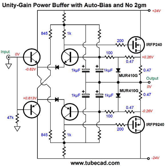
The 4-ohm outputs enjoy an impedance ratio of 1:8, while the 8-ohm outputs see a ratio of 1:4. The remaining big problem would be finding two unity-gain stable solid-state power amplifiers, as the usual IC amplifiers, such as the famous LM3886, aren't. Here is a circuit I sketched up, but haven't run SPICE evaluations on yet.
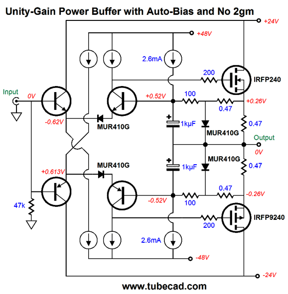
This power buffer only runs in constant-power mode at idle due to the rail voltages being regulated (assuming that the switcher power supply is being used, which offers 1% regulation of the output voltage) and the auto-bias feature. If it makes little sense to you, try this version instead.
Functionally, the two circuits are identical. The bootstrap capacitors effective make the six resistors act like constant-current sources that terminate into higher power-supply rail voltages. How does it work? As long as the output stage remains in class-A mode, the two MUR410G, ultra-fast rectifiers at the output stage, never conduct. Once the output stage leaves class-A window of current swing, these rectifiers engage, causing the remaining conducting MOSFET to see half of the source resistance it had at idle, so its effective transconductance doubles, which compensates for the other MOSFET having switched off. In short, no gm doubling, as the output stage presents a constant transconductance. Auto-bias and no 2gm at once. Once the output stage strays beyond the class-A window of current conduction, the rectifiers also double as signal-clipping devices, which prevent the 1kµF capacitors from ever becoming over charged, which would throw the auto-bias feature off target. The 2.6mA constant-current sources force a 0.26V voltage drop across the 100-ohm base resistors. The 1kµF capacitors allow 100% of the AC output signal to be delivered to the negative-feedback inputs of the two differential amplifiers. In other words, the output impedance will be quite low in spite of the 0.47-ohm source resistors, due to the high amount of negative feedback. Okay, let's wrap things up. The output tubes in the Circlotron run in strict class-A, swinging a maximum of 1.25A at 40V peak voltage swings. The IMC fills in the missing 3.75A of current, allowing 100W into 8-ohm loads. The IMC effectively sees a 10.666-ohm load, as 40V/3.75 = 10.666... ohms. Since the IMC holds two balanced power amplifiers, each effectively sees a load resistance of 5.33 ohms, when the speaker is an 8-ohm type. (Do not forget the current delivered by the Circlotron, which also eases the IMC's effective load impedance.) When the speaker's impedance is 4 ohms, on the other hand, things dramatically change. The same 100W of output will require only 28.28Vpk but 7.07Apk. The output tubes in the Circlotron no longer put out 1.25Apk of current, as 28.28V/32 ohms equals only 0.99375A, so the IMC must make up the 6.2A difference to get to 7.07Apk. This means that each of the two IMC power amplifiers effectively sees a load resistance of 2.28 ohms, which is plenty low. Fortunately, the each of the balanced amplifiers in the IMC need only swing 14.14Vpk into the load. Unfortunately, this means that the amplifier will undergo +/-14.14V output swing but operate under +/-24V of power supply voltages, which means more dissipation for the amplifiers. Thus, very robust amplifiers are required and big heatsinks. If chip amplifier were used, then something like what I purposed back in blog post number 281 should be used:
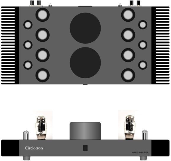
Now, 6.2A added to the heater string draw of 2.5A yields a peak current draw of 8.7A. In other words, the 9.8A switcher power supply no longer looks so over built. And adding a switcher power supply no longer seems the easy solution it had at first. Indeed, a 600VA 36Vac toroid in a convention power supply might prove the better way to go. What would such a beast look like? I made the following drawing for post number 256.
This sketch was meant to be for a hybrid stereo amplifier, so imagine only one set of inputs and outputs—and possibly only one toroid power transformer.
Next Time
User Guides for GlassWare Software
For those of you who still have old computers running Windows XP (32-bit) or any other Windows 32-bit OS, I have setup the download availability of my old old standards: Tube CAD, SE Amp CAD, and Audio Gadgets. The downloads are at the GlassWare-Yahoo store and the price is only $9.95 for each program. http://glass-ware.stores.yahoo.net/adsoffromgla.html So many have asked that I had to do it. WARNING: THESE THREE PROGRAMS WILL NOT RUN UNDER VISTA 64-Bit or WINDOWS 7 & 8 or any other 64-bit OS. I do plan on remaking all of these programs into 64-bit versions, but it will be a huge ordeal, as programming requires vast chunks of noise-free time, something very rare with children running about. Ideally, I would love to come out with versions that run on iPads and Android-OS tablets.
//JRB
|
|
Kit User Guide PDFs
Only $12.95 TCJ My-Stock DB
Version 2 Improvements *User definable Download or CD ROM www.glass-ware.com |
||


| www.tubecad.com Copyright © 1999-2016 GlassWare All Rights Reserved |