| John Broskie's Guide to Tube Circuit Analysis & Design |
28 May 2017 Post Number 381 I am being hammered by orders, since the shipment of PCBs arrived two weeks ago. At the same time, I am keen to make post number 400 this year, so I dare not slack of on posting. Thus, I went digging for schematics that I had drawn but hadn't posted yet. I found the Aikido differential amplifier stage, which fortunately keeps the differential theme going. And as H. L. Mencken so rightly pointed out,* "a certain co-ordination" of ideas can be enough to make a practitioner celebrated; indeed, even immortal."
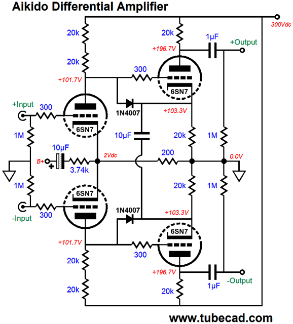
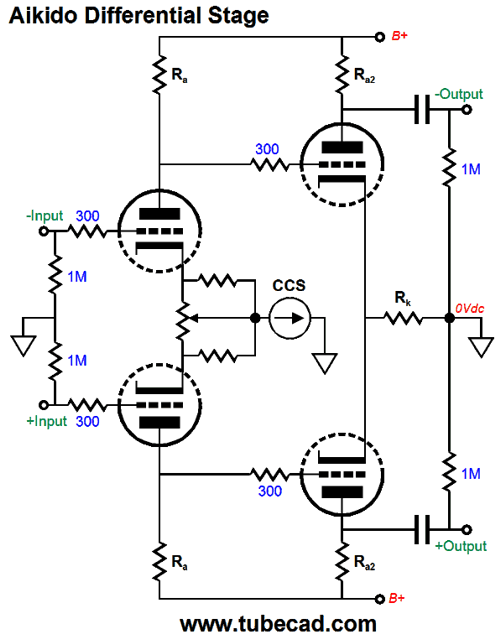
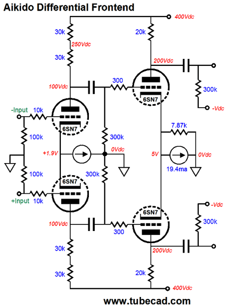
Aikido Differential Amplifier (I get asked all the time what does "Aikido" mean. It is a Japanese martial art [and philosophy] created by Morihei Ueshiba back in the 1920s. See post 336 for more details. But when I use the title, marker, label, "Aikido" it means a clever topological arrangement for preemptively canceling power-supply noise from leaking into an amplifier's output. I have applied my Aikido Mojo to cascodes, cathode followers, cathode-coupled amplifiers, grounded-cathode amplifiers, grounded-grid amplifiers, plate followers—all share the same goal: a vastly enhanced PSRR.)
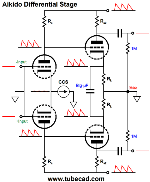
The above circuit is from Post 374 and shows how null the power-supply noise at the output when the input differential amplifier uses a shared cathode resistor, not a constant-current source. We inject a sampling of the power-supply noise at the nexus between cathodes, so that differential amplifier's PSRR can worsen! (In chess we would use !!?) Our goal is that the amount of power-supply noise that flows into the following differential amplifier grids becomes amplified and inverted at the outputs by a gain of -1. And as 1 -1 = 0, the power-supply noise cancels at the output.
In terms of AC signals, the second stage holds only one cathode resistor, which is why you only see one shared cathode resistor in the above illustration. In fact, if we juggle the second stage's plate resistor value, we can lose the 10µF capacitor and 3.74k resistor. The math isn't hard, but it does get thick. Still, it would be nice to limit our formulas to one, a relatively simple one at that.
If we replace the first stage's shared cathode resistor with a constant-current source, we will instantly know what the PSRR of the first stage will be, i. e. zero. Yep. All the power-supply noise at the B+ connection will leak into the two outputs. Now with the constant-current source in place, we can take the gain formula and solve for Rk for the second differential amplifier.
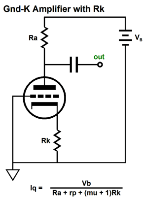
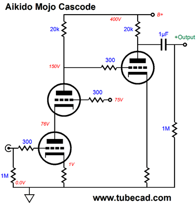
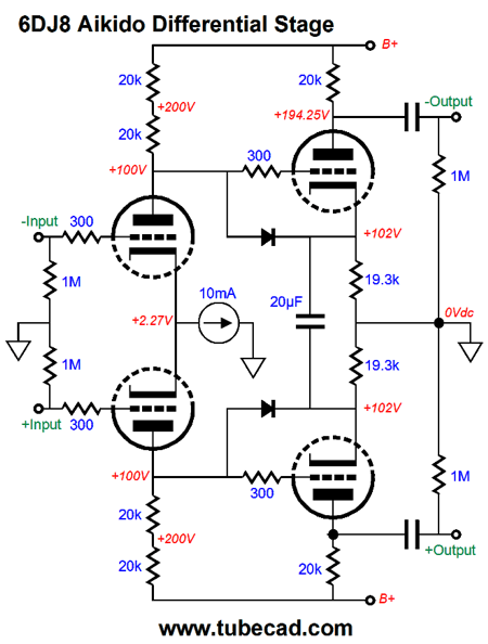
The formula for finding the gain of a grounded-cathode amplifier with an unbypassed cathode resistor is: Gain = muRa / (Ra + rp + [mu + 1]Rk) Now if set the gain to inverse of the amount of power-supply noise at the first stage's outputs and solve for either Rk or Ra, we arrive at a noise null. For example, if 50% of the ripple is presented to the grounded-cathode amplifier's grid, then the inverse of 0.5 is 2, so we will need a gain of two (+6dB) to null the power-supply noise at the output. With the addition of the constant-current source to input differential amplifier, we 100% or 1 of the power-supply noise at its two outputs, so we strive for a second-stage gain of 1, as the inverse of 1 is 1. Rk = ([mu - 1]Ra -rp) / (mu + 1) This gives us the result for a single triode in a grounded-cathode stage. Thus, the following circuit would work. The cascode input stage offers virtually no PSRR, so almost all the B+ ripple will appear at the second stage's grid. By setting the second stage's cathode resistor to a value slightly less than the plate resistor value, we can achieve a power-supply-noise null. The grounded-cathode's cathode resistor is unmarked, as the value would depend on the triode used. (The cascode could be replaced by a pentode amplifier.) In the following circuit, the second stage offers no gain, but it does strip away the power-supply noise and restores the input signal phase at the output.
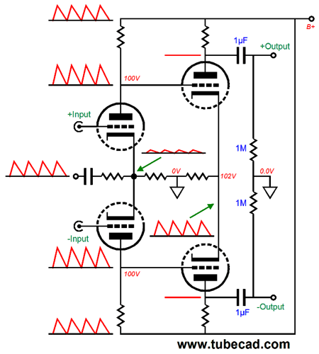
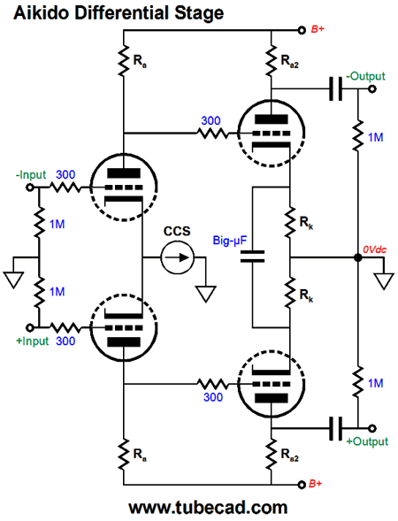
What will prove confusing to many is that the differential amplifier offers two gains: a different gain and a common-mode gain. We are only concerned with the last gain here, so we can use the previous formula. How's that? Look at the schematic below and note how if the second differential amplifier sees the same signal at both its inputs, the Big-µF capacitor falls out of the equation, as it sees no differential signal, as both of its plates see the identical signal.
The goal is to achieve a common-mode gain of 1 from second differential amplifier stage, as this will result in a power-supply-noise null at the output.
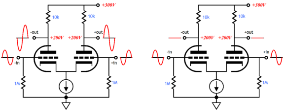
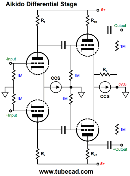
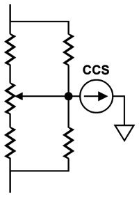
Wonderful, John, but what if we use a constant-current source with both the first and second differential amplifiers? This does pose a problem, because the addition of the constant-current source vastly improve the CMRR, we will never see anything close to a common-mode gain of 1. The solution is easy: just shunt the second constant-current source with a resistor equal to half the value of Rk.
Thus, the formula becomes: Rk = ([mu - 1]Ra -rp) / 2(mu + 1) Wait a minute; doesn't the shunting resistor undo the second stage's high CMRR? Yes, it does. Indeed, we get no CMRR; instead, we get common-mode gain of 1 (0dB). But why would we need any CMRR when the first stage already offers a huge CMRR? It is the balanced input signals that must be scrubbed clean of common-mode signals (usually, just noise). In addition, the above circuit does away with the Big-µF capacitor and gives the second stage triode a lot more voltage to operate within. We needed the Big-µF capacitor in the original circuit due to the DC coupling between stages and the uncertainty of equal plate voltages on the first stage, a problem that arises all the time in reality and never in the world of SPICE simulations. One workaround is to use a potentiometer to set the DC balance between the input stage's plate voltages.
Many love potentiometers. I don't. Indeed, I fear them, as they can make noise or lose contact. The two added resistors add a degree of safety and work to unload the potentiometer. I often add two more resistors to the above circuit, one on each end of the potentiometer.
Think of it as wearing a belt and suspenders at the same time. (The world is not a linear place to live. While I might find the above potentiometer improvement to be the least interesting thing on this page, some of my readers might disagree, finding it the only interesting item. I remember hearing on the BBC the story about native jungle people who were the subject of a documentary being flown to England after the filming. These people had no other contact with the advanced world. They found the airplane, cars, skyscrapers, TVs, smart phones to be okay, but what really thrilled them was seeing arrows with feathered ends [fletching] at a sporting goods store, as their own arrows were vane-less. Now these feathers were something special, something that they could actually use.)
Uses for the Aikido Differential Amplifier
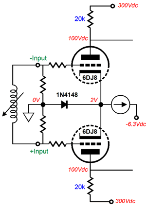
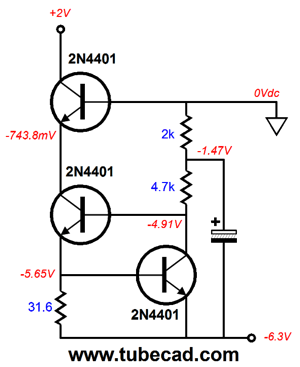
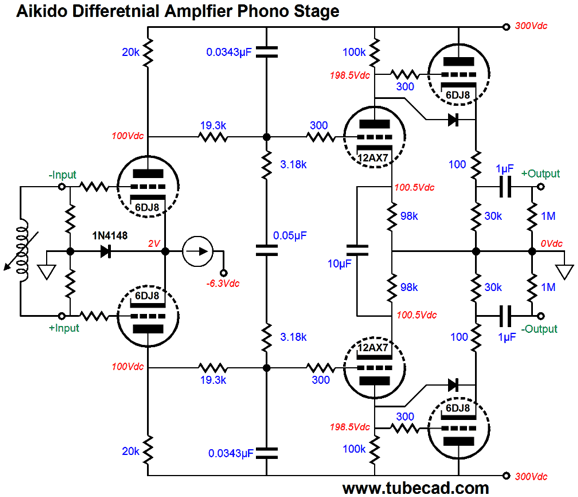
A constant-current source terminates into a -6.3Vdc power-supply rail, which can be also used to power the 6DJ8's heater element. Why not just ground the current-source? One problem is that we cannot use the LM334, as its limit is 10mA and we need 20mA of current flow. Of course, we could double up two LM334s in parallel or use an LT3092, which is good for up to 100mA. The LT3092, however, only comes in surface-mount packages, which is a pain. Moreover, if a different tube is used, such as the 12AX7, then neither IC constant-current source will work, as both would be voltage starved. The 1N4148 diode is a safety device that only is forward biased at turn-on, when the triodes have yet to heat up and conduct current. Once the triodes are hot, the diode becomes reversed biased and ceases to conduct. The discrete alternative is the following.
Three 2N4401 NPN transistors are used. In SPICE simulations, the output impedance came in at a tad over 3Meg. The unmarked capacitor can be just about any value, from 100µF to 1kµF. After the input stage comes passive RIAA equalization, then the second differential amplifier (the Aikido differential amplifier) and ends with balanced cathode followers.
The passive RIAA equalization is not ground referenced, but B+ referenced. Why? If we ground referenced it, less than 100% of the power-supply noise will appear at its outputs. Worse, the power-supply noise will be frequency contorted and phase shifted, making a noise null impossible. The 6DJ8-based cathode followers see 100V cathode-to-plate voltage and the cathodes sit at 200V, which means that a ground-referenced heater power supply cannot be used with them. The solution is to attach the input triode heaters to the -6.3V power-supply rail and give the other tubes a heater supply that is referenced to 150V. This is a pain. One workaround that would allow a single heater power supply referenced to 50V would be the following.
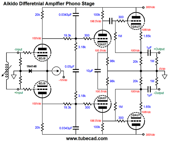
If more gain is needed, say for a moving-coil phono cartridge, then the following version would work.
Three differential amplifier stages are employed, the last being an Aikido differential. Note the 9.1k cathode resistor. The input stage uses two independent constant-current sources, which ensures that each plate sees the same plate voltage, which allows us to DC couple the second differential amplifier stage without the fear of big DC imbalances. The two cathodes are AC bridged by the 1µF film capacitor and the 1kµF non-polarized electrolytic capacitor. The RIAA equalization is once again B+ referenced and balanced cathode followers end the circuit. If a low output impedance is not needed, which in most cases it won't be, the cathode followers could be removed and the outputs taken directly at the last differential amplifier plates. Another possible use for the Aikido differential amplifier is as a microphone preamp. The amount of gain realizable from cascading differential amplifiers is staggering. For example, by using 6DJ8 triodes a gain of 57dB (1:735) is possible.
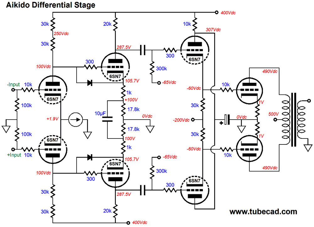
That is a lot of gain; and when we consider the PSRR figure of -53dB, the performance is even more impressive. If we do not need this gain, we can replace all the triodes with 12AU7 triodes and the 19.3k cathode resistors with 18.7k resistors; the resulting gain is now +46dB (1:200). We began with a phono stage, so let's end with a power amplifier.
The idea behind this circuit is that we need a lot of gain to drive low-mu power output tubes, such as the 300B. At the same time, we do not want to experience blocking distortion due to coupling capacitors being charged during positive grid excursions with the output tubes. The cathode followers DC couple to the grids, so no coupling capacitors are there to charge up. Coupling capacitors are safely used, however, between the Aikido differential input stage and the cathode followers. The gain from the Aikido differential input stage shown above is 150, which means that a +/0.1Vpk pair of balanced input signals will provoke +/-15Vpk voltage swings from the Aikido differential input stage. Since only 10mA is needed from the constant-current source, an LM334 can be used with a 6.8-ohm set resistor. Two 30k resistors are used in series to lower voltage-induced distortion and to halve the dissipation by each resistor. If even greater output swings are needed, say to drive a pair of 845 driver tubes, then the following Aikido differential input stage is the one to use.
The gain comes in at 273 and close to 200Vpk of output swing is possible.
Next Time
//JRB
*Quote from the forward to In Defense of Women
(Link)
Patreon My second goal is to gather 1,000 patrons, which may seem a crazy goal, but then the world is a big place. I have 965 patrons to go. If you enjoyed reading this post from me, then you might consider becoming one of my patrons at Patreon.com.
User Guides for GlassWare Software
For those of you who still have old computers running Windows XP (32-bit) or any other Windows 32-bit OS, I have setup the download availability of my old old standards: Tube CAD, SE Amp CAD, and Audio Gadgets. The downloads are at the GlassWare-Yahoo store and the price is only $9.95 for each program. http://glass-ware.stores.yahoo.net/adsoffromgla.html So many have asked that I had to do it. WARNING: THESE THREE PROGRAMS WILL NOT RUN UNDER VISTA 64-Bit or WINDOWS 7 & 8 or any other 64-bit OS. I do plan on remaking all of these programs into 64-bit versions, but it will be a huge ordeal, as programming requires vast chunks of noise-free time, something very rare with children running about. Ideally, I would love to come out with versions that run on iPads and Android-OS tablets. //JRB |
E-mail from GlassWare Customers
High-quality, double-sided, extra thick, 2-oz traces, plated-through holes, dual sets of resistor pads and pads for two coupling capacitors. Stereo and mono, octal and 9-pin printed circuit boards available.
http://glass-ware.stores.yahoo.net/ Support the Tube CAD Journal & get an extremely powerful push-pull tube-amplifier simulator for TCJ Push-Pull Calculator
TCJ PPC Version 2 Improvements Rebuilt simulation engine *User definable
Download or CD ROM For more information, please visit our Web site : To purchase, please visit our Yahoo Store: |
|||


| www.tubecad.com Copyright © 1999-2017 GlassWare All Rights Reserved |