| John Broskie's Guide to Tube Circuit Analysis & Design |
04 June 2016 Post 382 An additional hunt through my hard drive uncovered schematics from 2010 that I intended to base a post upon, but which I failed to do. Too many schematics, too little time. Note that I have removed the Google ad. I hit one of my Patreon goals, which means no more annoying Google ads. Good riddance. It will take a long time, however, to purge all the HTLM code from 380 pages and repost.
Electrostatic Headphone Amplifiers? Audiophile: I don't like electrostatic headphones. Me: Really, which tube electrostatic headphone amplifier did you use? Audiophile: I didn't use a tube headphone amplifier, just the solid-state one that came with the headphones. Me: Okay, how do you know whether you don't actually like solid-state electrostatic headphone amplifiers or electrostatic headphones or both?
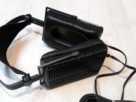
I know that with my own Stax Lambda Pro electrostatic headphones, which are amazingly revealing, the headphone amplifier in use makes a huge difference. Even within a tube-based electrostatic headphone amplifier, I could hear power-supply capacitors making a big difference. At first the amplifier disappointed, but after about a ten to fifteen minute warm-up, it sounded fine. This troubled me greatly, so I went hunting to find the cause. Heat. Hot electrolytic capacitors sounded better than cool ones. This I discovered by blowing a hair dryer at the power-supply capacitors with the amplifier turned off, and then turning it on and hearing sweet sound.
I then tried several different capacitors and found the Rubycon photo-flash types to sound best. One problem: these capacitors cannot tolerate any charging current at any voltage near their rated voltage; if they do see any steady charging current, they die. I then tried two in series, with shunting resistors to ensure equal voltage division, and they survived. Ideally, large-valued film capacitors should be used after an RC-filter resistor; this way the electrolytic capacitors would take the beating after the rectifiers, while the film capacitors delivered sweet sound. On the other hand, maybe not. I have noticed that all electrolytic capacitors have greatly improved over the decades since I first built an electrostatic headphone amplifier (about 1980).
On to the schematics. One thought that I have long entertained is that it would be great to have a dual use amplifier that powered either loudspeakers or electrostatic headphones. I have held this view ever since I performed a dangerous experiment 37 years ago.
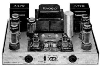
I owned Audio Technica ATH-70 electret headphones, which held pre-polarized diaphragms, so no biasing voltage was needed. I used a 200W solid-state power amplifier to drive the step-up transformer. (Everyone assumed that it was there to drive my speakers.) Even with the big 200W amplifier, the sound was lackluster. I thought why not just attach the headphones to the plates of the EL34s in my Dynaco St-70 tube amplifier. Crazy dangerous: do not do this at home!
I unattached the speakers and clipped on some leads and listened away. Vastly improved sound resulted, more immediate, greater clarity and transparency.
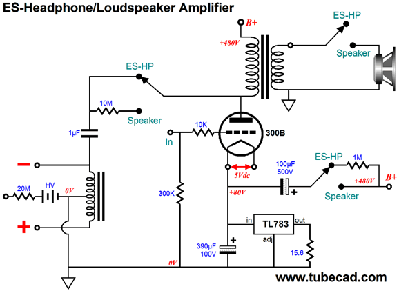
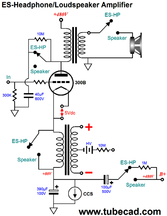
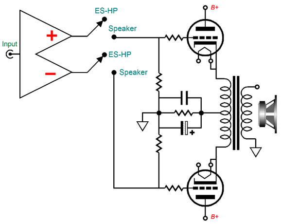
Since we face an either-or choice between listening to speakers or headphones, it would be fun to own a tube amplifier that could drive both. The following design uses a single 300B output tube per channel to drive either speakers or electrostatic headphones.
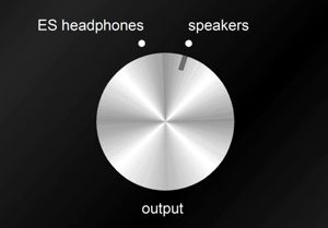
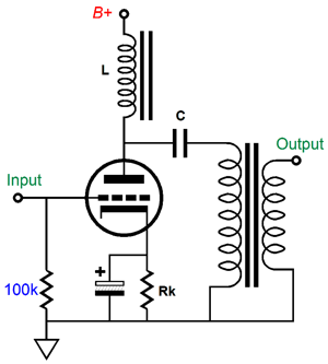
With the six-pole, two-position rotary switch in the first position, the speaker is disconnected, so the output transformer's primary becomes an inductor (choke), which allows the plate to swing up and down freely. The center-tapped inductor creates the two balanced output signals for the electrostatic headphones. Since no idle current flows through this inductor, a nickel core can be used. The 100µF/500V capacitor attaches to the 1M resistor, which keeps the capacitor energized, but not AC coupled to the B+ voltage, so no Aikido mojo is employed. Think of this arrangement as a para-feed amplifier topology.
With the six-pole, two-position rotary switch in the second position, the speaker is attached to the transformer's secondary, but the center-tapped inductor connects to a 10M resistor, which keeps the 1µF capacitor energized, but AC decoupled. The 100µF/500V capacitor now attaches to the B+ voltage, so the Aikido mojo is fully employed, greatly improving the PSRR. The TL783 is configured as a constant-current source, which will auto-bias the output tube. Another possibility is to use the 300B in a cathode-follower configuration.
Bang. Bang. I can hear many heads exploding. With the two-position rotary switch in the first position, the speaker is disconnected, so the output transformer's primary becomes an inductor (choke) that forms an LC filter with the 40µF capacitor that will lock 300B's plate in place and shield the plate from power-supply noise. The 300B's cathode will then swing up and down, driving the step-up transformer that drives the electrostatic headphone stators. With two-position rotary switch in the second position, the speaker connects to the output transformer's secondary band the Aikido-mojo 100µF capacitor attaches to the B+ connection, thereby reducing the power-supply noise at the output. The 40µF capacitor remains charged up to the B+ voltage through the 10M resistor, but imposes no real load on the 300B's plate.
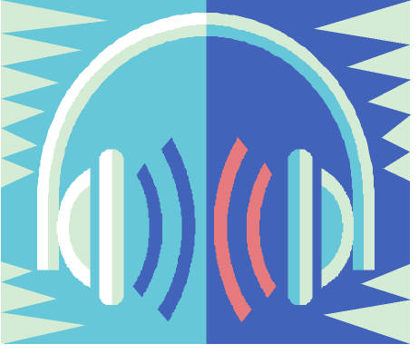
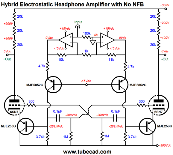
Hybrid Electrostatic Headphone Amplifier
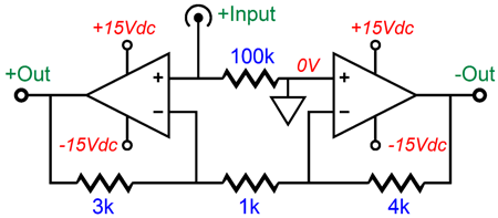
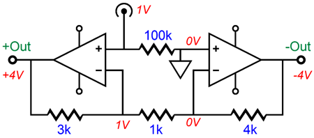
Let's start with the OpAmps. A simple way to get a balanced output out of a single-ended input signal is the following circuit.
An input signal of 1Vpk becomes a balanced output of +/-4Vpk, as the left OpAmp function as a non-inverting amplifier, while the right OpAmp functions as an inverting amplifier. The common-mode rejection ratio (CMRR) is equal to inverse of the gain, which is not all that high in the above example (-12dB), but is quite good in the hybrid amplifier due to its gain of 301 (-49.5dB).
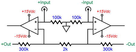
The left OpAmp's gain is equal to (3k + 1k)/1k, while the right OpAmp's gain is equal to 4k/1k. If a balanced input signal is used, we can use the following arrangement.
Note the 2k and two 300k resistor values, which result in +/-1Vpk of balanced input signals being amplified to +/-300Vpk of balanced output signal.
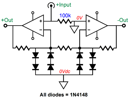
The diodes are used as safety devices, which protect the OpAmp's inverting inputs from seeing excessive voltage. Why should they ever see excessive voltage? Easy; at startup, the 6SN7 is cold and not conducting, so without the diodes, the OpAmp's inverting inputs would both see +300V; not good. With the diodes in place, the highest positive voltage they can see is about +1.4Vpk. So why are the other diodes there? Another possibility that comes to mind is someone plugs in the wrong tube, which could short the 20k resistor strings to the negative power-supply rail through the 3.74k cathode resistors; once again, not good. In general, solid-state and high voltage do not mix, so it is best to assume the worst will happen and take preventive safety measures. Placing the plate-load and feedback resistors in series helps lower voltage-induced distortion from the resistors and helps with heat dissipation. Assume that the tube will arc or short out or that the wrong tube will be plugged in, then figure out the worst case dissipation from the plate load resistors. Well, 600V across a 60k resistance would equal 6W of heat, so using at least 20k/2W resistors would be the prudent thing to do. (I would probably use six 2W 10k resistors instead.) Three power supplies will be needed: a regulated +/-15V for the OpAmps, an unregulated +/-300V for the tube output stage, and a heater power supply of the output tubes, which should be referenced to about -250Vdc. The 6SN7-based output stage is cross-coupled, which increases its gain, while still allowing the OpAmps to control the DC offset at the balanced outputs. (See post 166 for additional information on cross-coupled circuits and additional hybrid electrostatic headphone amplifiers. While you are at, check out post 139.)
The OpAmps drive the 1k resistors, whose current flow travels down to the 3.74k collector resistors, which in turn drive the bottom PNP transistors, which then drive the cathodes, resulting in non-inverted signal at the plates, which get returned to the OpAmp inverting inputs, resulting in two complete negative feedback loops. If the thought of such a complex feedback loop scares you (no high-frequency-compensation capacitors are shown, but would be needed), then you could forgo the global feedback loops and use two shorter loops instead.
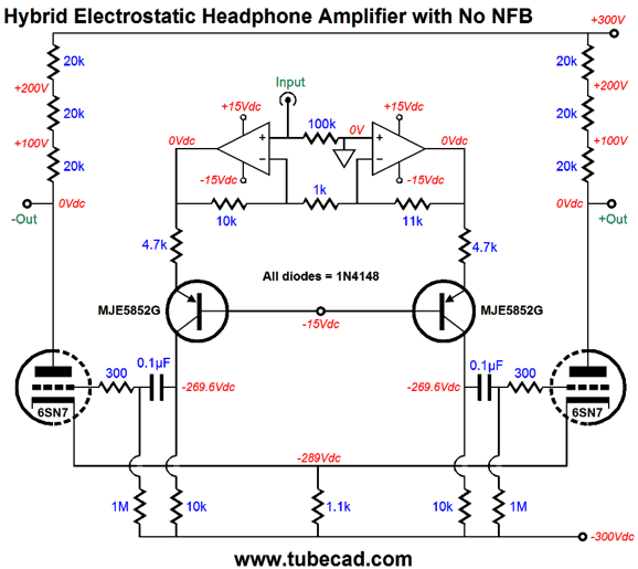
In the above circuit, the OpAmp's have no idea what the output signals to the electrostatic headphones look like, as their feedback loops only extend to their outputs. Note the removed diodes, which are not needed here. We can simplify even further.
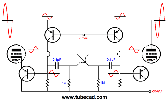
The two 6SN7 triodes share a single cathode resistor. Interestingly enough, this simpler version enjoys a better PSRR than the previous version, but not better than the first version. Does this matter, as the electrostatic headphones are intrinsically differential devices, which means as along as the noise is shared equally between the stators and in phase, no sound should emerge to annoy us. Yet, my own experiments 30 years ago revealed that I preferred the sound from higher PSRR electrostatic headphone amplifiers. One possibility is that some slight imbalance in the electrostatic headphone design undoes some of their differential functioning. Or, perhaps the power-supply noise re-circulated through the amplifier or the noise mixed with the signal at the grids and caused intermodulation distortion (IMD). Or, maybe, I am just prejudiced against power-supply noise in general, detesting it even when I cannot hear it. Returning to the dual-use amplifier idea, the following idea appeals to me greatly.
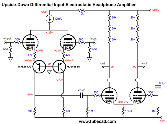
The concept is simple enough: we use a high-quality electrostatic headphone amplifier to either drive the headphones or the grids of a push-pull cathode-follower power amplifier. Nice. The cathode-follower operation provides both low distortion and low impedance, so no global feedback loop is needed. Note the heater elements on the output tubes. These heaters must be referenced to their respective cathodes and powered by separate heater power supplies, either AC or DC, as the cathode will make huge voltage swings. Also note how the single cathode resistor appears at the primary center-tap. Speaking of heaters, when the amplifier is driving electrostatic headphones, we should de-energize the output tubes heater power supplies. (We could then power up a red LED under the output tube to make it look as if it were glowing.) One last circuit, which is an orphan circuit from post 380. The following design uses an Upside-Down differential input stage to drive the conventional differential output stage.
A balanced pair of input signals are required, as shown. You could, however, ground either input and use the other to accept an unbalanced input signal, at the price of half the gain. The 6DJ8 input tube sees 5mA of current flow per triode, as do each 6SN7 triode, bringing the total current draw to 20mA per channel. Two heater power supplies will be needed: one for the 6DJ8 tubes, which should be voltage referenced to about +50Vdc; and one for the 6SN7 tube, which should be referenced to about -250Vdc. Each MJE5852G PNP transistors could be replaced by two MJE350 transistors in cascode, with each device seeing a 125Vdc voltage drop. No global negative feedback is employed, but two loops could be added with some fiddling of the topology. I wouldn't bother. In SPICE simulations, the PSRR came in at -28dB, which is fine, but not great. Once again, it may not matter, as the headphones will not see the ripple differentially. The PSRR could be improved, however, by making the -300V power supply rail a tad more robust by making its reservoir capacitor about 10% larger in value than the +300V power-supply rail capacitor, say 330µF versus 300µF. But this is a subtlety best left for those with a good oscilloscope and great patience. (Most electrolytic capacitors are 20% or 10% devices, so a "330µF" marked capacitor might actually hold less capacitance than a "300µF" marked capacitor.)
//JRB
Special Thanks If you have been reading my posts, you know that my lifetime goal is reaching post number one thousand. I have 618 more to go. I should easily be able to hit post 400 this year. My second goal is to gather 1,000 patrons. I have 965 patrons to go. If you enjoyed reading this post from me for the last 18 years, then you might consider becoming one of my patrons at Patreon.com.
//JRB
User Guides for GlassWare Software Since I am still getting e-mail asking how to buy these GlassWare software programs:
For those of you who still have old computers running Windows XP (32-bit) or any other Windows 32-bit OS, I have setup the download availability of my old old standards: Tube CAD, SE Amp CAD, and Audio Gadgets. The downloads are at the GlassWare-Yahoo store and the price is only $9.95 for each program. http://glass-ware.stores.yahoo.net/adsoffromgla.html So many have asked that I had to do it. WARNING: THESE THREE PROGRAMS WILL NOT RUN UNDER VISTA 64-Bit or WINDOWS 7 & 8 or any other 64-bit OS. One day, I do plan on remaking all of these programs into 64-bit versions, but it will be a huge ordeal, as programming requires vast chunks of noise-free time, something very rare with children running about. Ideally, I would love to come out with versions that run on iPads and Android-OS tablets.
//JRB |
Kit User Guide PDFs
And
High-quality, double-sided, extra thick, 2-oz traces, plated-through holes, dual sets of resistor pads and pads for two coupling capacitors. Stereo and mono, octal and 9-pin printed circuit boards available.
Designed by John Broskie & Made in USA Aikido PCBs for as little as $24 http://glass-ware.stores.yahoo.net/
The Tube CAD Journal's first companion program, TCJ Filter Design lets you design a filter or crossover (passive, OpAmp or tube) without having to check out thick textbooks from the library and without having to breakout the scientific calculator. This program's goal is to provide a quick and easy display not only of the frequency response, but also of the resistor and capacitor values for a passive and active filters and crossovers. TCJ Filter Design is easy to use, but not lightweight, holding over 60 different filter topologies and up to four filter alignments: While the program's main concern is active filters, solid-state and tube, it also does passive filters. In fact, it can be used to calculate passive crossovers for use with speakers by entering 8 ohms as the terminating resistance. Click on the image below to see the full screen capture.
Tube crossovers are a major part of this program; both buffered and un-buffered tube based filters along with mono-polar and bipolar power supply topologies are covered. Available on a CD-ROM and a downloadable version (4 Megabytes). |
||


| www.tubecad.com Copyright © 1999-2017 GlassWare All Rights Reserved |