| John Broskie's Guide to Tube Circuit Analysis & Design |
03 April 2018 Post Number 418
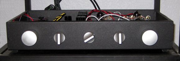
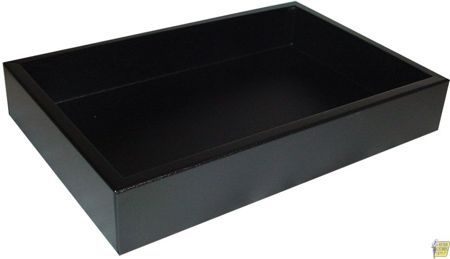
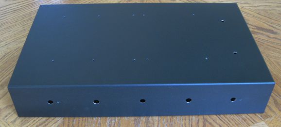
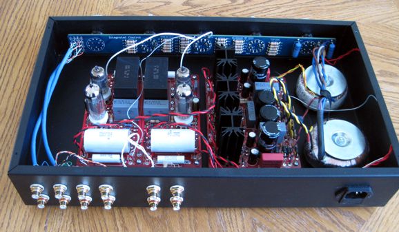
Pretty Boxes What was the secret? "Fully 50% of the cost of audio gear must go to cosmetics, the fancy casework and knobs; the other 50% to the electronics." While most audiophiles will admit that you cannot judge a book by its cover, they believe that you can judge audio gear by its enclosure. If you are an audio Puritan, then this obsession with shiny metal betrays a sinful distraction from sonic truth, dare I say it, The Absolute Sound. In contrast, if you are a consummate consumer-goods hedonist, then there is no problem, as you know that someone is only as exalted as is his consumption; the shinier the knobs, the more sublime and worthy of envy is the purchaser. Who is right? Whose money is at stake? Whoever pays for it gets to judge. A third path exists, the compromise route. This way avoids $50 RCA jacks and milled solid-billet enclosures, while also steering clear of butt-ugly gray Bud Boxes. This was the path I took recently, when I decided to take my new Aikido noval Rev. E line-stage amplifier out of my test box and place it in something more appealing (and more transportable). Deep within my parts closet, resided a Hammond black-coated steel box 17in wide and 10in deep and 3in tall. It's a fine looking metal box, but the sheet metal is a bit thin. The box cost less than $40.
Now, if I owned a magic wand, I would have summoned up a hefty steel enclosure with heavy copper plating whose corner seams were welded and filed and whose exterior was plastic coated and baked. The copper plating offers low resistance, which protects against RFI; the steel insulates against magnetic interference, being magnetically permeable. What about everyone's favorite: aluminum? Aluminum, in contrast, offers neither low-resistance nor the ability to sustain a magnetic field within itself; in other words, it is not ferromagnetic. In short, we should avoid brass, tin, and non-magnetic stainless steel. Okay, what about a sandwich of silver atop soft steel atop aluminum? If you have the cash to burn, go for it. Actually, the best might be a copper-plated steel chassis that houses a slightly smaller aluminum chassis, so a small air-gap exists around the smaller box. Having said all this, I know that many fret over steel enclosures, fearing sonic contamination. Well, I, too, have been nervous. If you are passing any audio signal through the chassis, you should certainly worry. On the other hand, if no currents flow through the chassis and if the PCB or point-t0-point wiring stands at least half an inch above the chassis and if we are dealing with a phono stage or line-stage amplifier, then you can worry much less—if at all. Big power amplifiers, however, do force enough current to worry about unintended inductive coupling between components and enclosure.
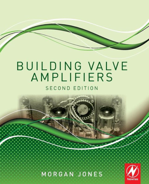
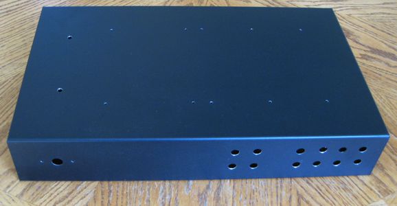
If you are new to metalwork or chassis fabrication, the absolutely best thing you can do is buy Morgan Jones book, Building Valve Amplifiers. Consider it your bible. With over 600 pages, it holds important information you need to know, no matter how experienced you might be. After reading it, I felt possessed with the urge to build something. The book holds three sections. The first deals with fabrication; the second, with testing and measurement and trouble-shooting. The last 200 pages are devoted to actual tube-audio design projects, such as a balanced phono stage. A must-own book. So, I had a metal box and some fancy knobs and RCA jacks, but what I needed was a plan. The first step is to make sure everything will fit. Just because you can fit everything in a small box does not mean that you should. Time after time, I have wished for an extra inch here, a few millimeter there. Remember that switches and RCA jacks and power sockets and PCB standoffs all take up space. The next step is to mark off where the pilot holes will fall across the chassis. With rulers, T-squares, patience, and good eyes, you can mark off all the hole positions with a pencil. I prefer to using a drawing program, however, to lay down the hole positions, which I can then print to a sheet of paper. The paper is then punctured with a needle wherever a pilot hole appears. The sheet is then positioned on the chassis and taped down with masking tape. Be sure to measure the paper to ensure that it actually conforms to the your desired measurements. (I always place the PCB directly over the paper to see if the mounting holes line up.)
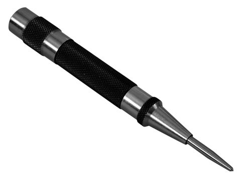
Now it is time to use a metal punch. If a steel chassis is used, then you can get away with using the metal punch directly. If an aluminum or copper chassis is used, then extra care is required, as the weak and soft metal will deform from the blows with the punch. The workaround is to place a wooden or metal structure under the chassis where the punch will fall.
After applying all the punch marks, we drill each mark with a small drill bit. I use a hand-powered drill, as it offers more control than a power drill.
The next step requires either a drill press or a power hand drill. I have used both, and I prefer the drill press. Unfortunately, a drill press large enough and deep enough to drill a big audio chassis is both expensive and huge. With either drill type, you will need drill bits designed to make clean holes in metal. This is important, as many drill bits are designed to both drill through wood and to do so quickly, but not smoothly; these are perfect for making a house, not audio gear. When I lived in Scotts Valley, I knew a fellow whose business was making super-precise holes in metal. Not an easy task, as metal expands with heat and most drills and drill bits are too coarse. His drill bits, in contrast, were in themselves precision items and cost between $30 to $300 each. I always apply a thin coat of thread-cutting fluid (a mix of oil, water, and soap) to the drill bits and I try to secure the metal before drilling, as bits sometimes jam. If I have the patience, I will cover the sheet metal with masking tape, so it is protected from scratching from the spinning spirals of metal shred coming off the drill bit. If a fancy face-plate needs drilling, extra care is required, such as clamping paper and an extra layer of sheet metal. Remember that small holes require fast spinning drills, while big holes require slow spinning. One speed does not fit all drill sizes. For this project, I was in a huge hurry, so I didn't expect perfection. Nonetheless, I am pleased with the results.
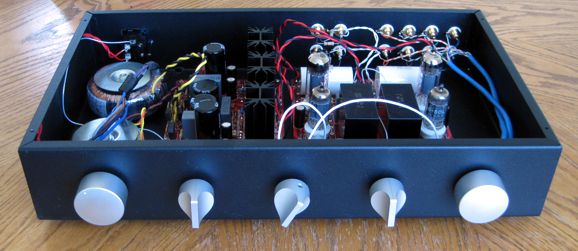
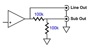
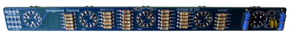
Only three wires leave the Integrated Control and terminate into the Aikido Noval PCB, left, right and ground. Note the four input and two output RCA jacks. My system needs sub-woofer output jacks. I place a -6dB, two-resistor voltage divider at each sub-woofer jack, as I want to prevent electrical back-feed or contamination from the sub-woofer amplifiers.
My view is that the two 100k resistors will limit potential sonic damage. Next, note the five-switch PCB that holds the signal selector and power switches, along with a three-switch stereo stepped attenuator. The attenuator is identical to the A3 stepped attenuator. This 15in by 1.4in PCB makes for much easier wiring and a cleaner interior. I used two four-twisted pairs CAT-5 cable to connect the input signal RCA jacks to the selector switch, which also made for an uncluttered interior.
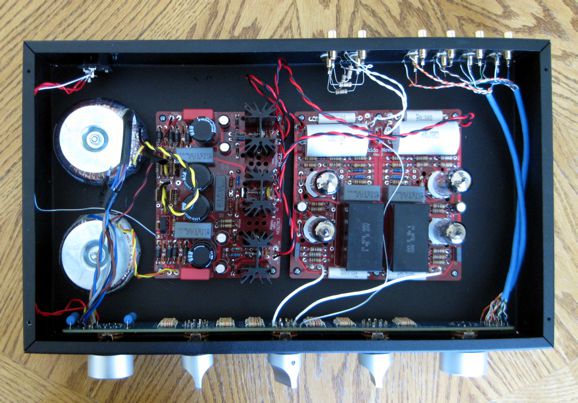
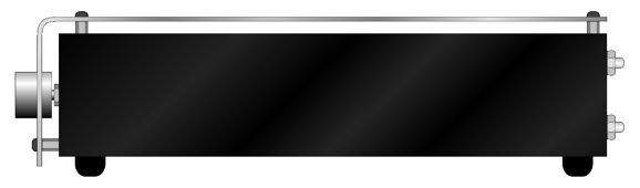
The power supply is the new PS-21, which holds a high-voltage regulator and two separate low-voltage heater regulators. Two 25VA, a 240Vac and a dual 12Vac, Triad power transformers power the PS-21. Sadly, the transformers were pulls from old projects and the leads were too short to get extra fancy in their layout. (I plan on trimming and placing the three pairs of power leads under the PCBs.) The AC receptor holds a fuse. All in all, I am quite pleased with what three hours of work could accomplish. It was the right balance of time and effort to result. If I had striven to attain perfection, it would still not be done—possibly it would never be done. The perfect is the enemy of the finished. If I had hastily finished it in one hour, however, I would curse myself daily, as I would be irked by the sloppy result. I worried that the Aikido might not sound as good as it had in my test box, as many changes had been made. It sounded just as good if not better than before. The better part bothered me. Why better? I then realized that in this new box, I had placed the 0,01µF 1kV CDE bypass capacitor in parallel with the main 1µF 1kV CDE coupling capacitor, whereas the bypass capacitors just floated in the text box. So there was difference. Somewhere, I have the top metal panel. (Actually, it is the bottom plate; I turned the box upside down.) I can place 1/2in hex aluminum standoffs in between the chassis and the top cover, which would provide breathing space across the top edges. Alternatively, I could hunt down a sheet-metal fabrication firm and have a thick piece of aluminum sheared, bent, punched, and powdered coated—or brushed and anodized.
The open gap would still be there and the front face would look more attractive.
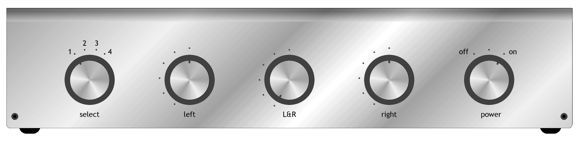
I own some gorgeous bead-blasted 1in-diameter aluminum knobs that would look stellar with such a faceplate.
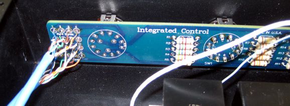
Integrated Control
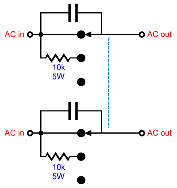
The power switch is a three-position type, with a center position that places two 10k power resistors in series with the incoming wall voltage, which softens the initial current inrush. The two high-voltage ceramic capacitors prevent arcing across the contacts.
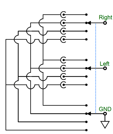
The four-position signal selector switch switches between left and right hot signals and between the common ground for each signal. In other words, when the CD player is selected, its ground attaches to no other signal source, such as an FM tuner or DAC or phono stage. This selector switch is identical with the Select-5 switch.
The three-switch stepped attenuator is identical to the A3. Each switch hold six positions. The center switch controls both channels and offers six coarse steps of either -6dB or -12dB steps of series attenuator. The left and right switches are are ladder attenuator and each channel gets its own switch and six steps of fine attenuation, either -1dB or -2dB; because the two outside switches are independent, we can use them to restore balance.
The Integrated Control IS NOT AVAILABLE and probably will never be at the GlassWare-Yahoo store. Why not? I just remembered why I never released the PCB and kit: it cannot be shipped in the flat-rate packages that I use from USPS, alas. Perhaps, one day it will be part of bigger kit, say one that includes a chassis.
In post 287, the following four OTL design rules appeared.
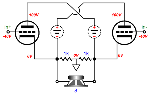
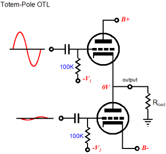
The totem-pole configuration requires dissimilar drive signal amplitudes for the top and bottom output tubes, as the bottom triode cathodes are fixed to the negative power-supply rail, while the top cathodes bounce up and down with the output signal and, thus, require far larger grid voltage swings than the bottom triode grids. In contrast, a circlotron amplifier requires equal amplitudes of drive signals for its output tubes.
Speaking of circlotron amplifiers, for the last three years, I have been wanting to discuss an email I had received. Sadly, I could not find it again. So, I must apologize for not having a name to credit; and I doubly apologize, if the reader was someone with whom I have had many exchanges.
As the reader saw it, the circlotron topology was intrinsically dangerous. Why? The loudspeaker sits perched, precariously perched as they say, between to high-voltage power supplies. Much like a man standing at the center of a teeter-totter, with a hungry tiger on one side and a hungry lion on the other side. The smallest imbalance, and he falls into one open mouth or the other. But an OTL was inherently safer, even if directly coupled to the speaker, as the top output tube's cathode was situated at ground potential.
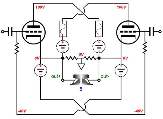
Okay, I have to admit that I was confused at first, but after some thinking I came to see why he feared the circlotron. It does look dangerous: two 140V floating power supplies, either of which could deliver 2,450 watts, if directly shunted by the loudspeaker. But how does the OTL totem-pole topology sidestep this danger? Or does it? Think about it: imagine one of the OTL output tubes arcs and the entire structure melts down, creating a dead short to either the -140V or the +140V power-supply rail. How does this differ from the circlotron? Well, that is like an act of God, a rare catastrophe; but the OTL totem-pole is—under normal operation—far safer, as its output naturally tends to center near 0V. Actually, the circlotron does the same; in fact, both its output tubes' cathodes sit near 0V. Under normal operation, it is effectively twice as likely to center at 0V, particularly if we garter-belt the output tubes, as shown below.
If the outputs drift off 0V, the countering DC grid voltage will buck the drift, as each output triode sees its grid move in the opposite voltage direction that its cathode is veering off towards. In this arrangement, both triodes are striving to balance at 0V. In contrast, only the totem-pole's top triode strives to center at 0V, as the bottom triode's plate is not nearly as sensitive to a shift in voltage as the triode's cathode is. Thus, in terms of safety, I would place the circlotron above the totem-pole OTL. In terms of ease of driving both output tubes, the circlotron is the clear winner, as each output tube sees the same amplitude of input signal at is grid, as each triode's cathode sees the same amplitude of output swing. The totem-pole OTL isn't as lucky, as its top triode's cathode isn't fixed, but moves with its input signal. Okay, so why aren't circlotron power amplifiers more popular? The answer is obvious: the need for two floating power supplies per channel, whereas a stereo totem-pole OTL can get away with one bipolar power supply. In addition, the circlotron seems to be wedded to balanced input signal, while the totem-pole OTL seems to be wedded to unbalanced input signals. Seems is not is. Both topologies can be made to accept either balanced or unbalanced input signals.
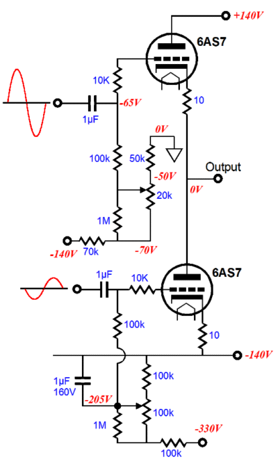
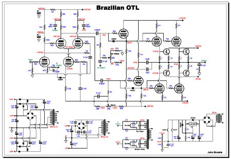
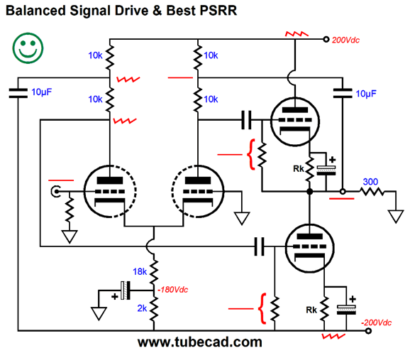
Third stipulation was the PSRR issues must be addressed. Here again the circlotron is the clear winner, as its balanced input signals are ground referenced, whereas none of the totem-pole OTL's input signals are. The top triode's input signal is output reference, while its bottom triode's input signal must be reference to the negative power-supply rail, or the negative power-supply rail ripple will be amplified. The solution offered in the Brazilian OTL, however, is elegant. The long-tail phase splitter's plate resistors terminate into two different "signals:" the output and the negative power-supply rail. The result is doubly good, as the needed unbalanced drive signals are realized and the PSRR is enhanced.
The last key design issue, safety, wasn't addressed in the Brazilian OTL. Ideally, a solid-state DC-window voltage comparator that uses two OpAmps to drive a relay that closes when its is safe to connect the OTL's output the the loudspeaker. The DC window might be +/-10mV. If the output stays within this voltage window for long enough to charge up the voltage comparator's internal capacitors, the OpAmps will engage the relay and the relay will short a 10k series resistor between the output and the loudspeaker. If the output stray off 0V for too long, the comparator will open the relay's contact and the speaker will see the 10k resistor in series with the output. The Brazilian OTL design went further than these four requirements, as it addressed the problem of positive-grid bias with the output tubes, the problem of establishing equal voltage and current swings for the driver cathode followers, and the problem of gm-doubling due to class-AB operation of the output stage. One item that caught my attention was that the fix for the Brazilian OTL driver cathode followers bore a slight resemblance to Bruce Rozenblit's patented zener solution to the inherent totem-pole OTL imbalance. Rozenblit's zener shunts the top cathode follower in his OTL.
As the output voltage swing positively, so too will the cathode follower's plate voltage. The zener limits the cathode-to-plate voltage swings that the top cathode follower will experience, but is it does nothing to establish drive balance between top and bottom output tubes. How could it, as the imbalance must be resolved in the phase splitter, not the cathode follower? Cathode followers are buffer circuits; they offer no gain. What we need is dissimilar output signals from the phase splitter.
Bruce's patented fix only fixes the problem of the top cathode follower swinging dissimilar current and cathode-to-plate voltage swings than the bottom cathode follower, but it does nothing to establish balanced drive. Now if Bruce had used two zeners and attached them to the long-tail phase splitter, then we would achieve both drive balance and PSRR enhancement.
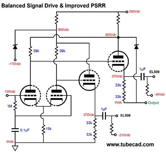
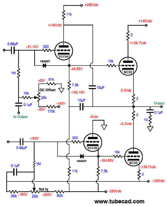
As you can see, the zeners take the place of the coupling capacitors in the Brazilian OTL. In fact, we could use both, zener and capacitor, in parallel. I prefer no zeners, as I know that the power-supply rail voltages will swell and contract with wall-voltage fluctuations and the capacitor work with these voltage variations, not against them. By the way, I did not omit grid-stopper resistors from the schematic of Bruce's OTL; he only uses them on the output tubes. Here is a more fleshed out version of the above design.
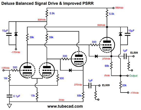
Note the essential grid-stopper resistors. Anyone who does not use grid-stopper resistors with cathode followers is just begging for oscillations. Also note the two protective diodes and the added 20k resistor at the output. Why is this 20k resistor there? In Bruce's design, the top cathode-follower's current flows entirely into the bottom output tubes. This creates an imbalance. With the added 20k resistor, the cathode-follower's current finds an alternative path to the negative power-supply rail. Surely someone reading this has built Bruce's OTL. If you have an hour to spare, rewire your OTL to conform to the above schematic and let me know how it turns out. Thanks. Before leaving the topic of getting the cathode-followers to operate in a balanced fashion, I should point out that there is an alternative way to setup the Brazilian OTL's cathode follower driver stage, as shown below.
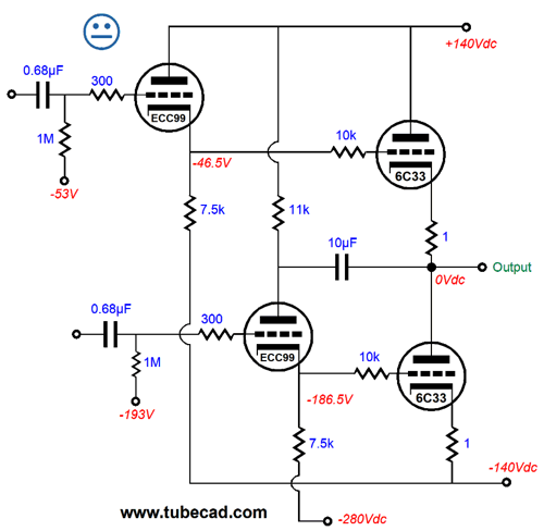
We still end up using two 10F capacitors, but we must add an additional 11k resistor, an 11k plate resistor to the top cathode follower. This approach unloads the top cathode follower, so it matches the bottom cathode follower. In contrast, the original approach made the bottom cathode follower work as hard as the top cathode follower did. Which approach is better? Probably this alternative, but it requires a 280Vdc power-supply rail that the previous design didn't. Mind you, getting the extra power supply rail voltage is not hard, but it does require more rectifiers and capacitors. Alternatively, we could use the 420Vdc B+ voltage and a much larger plate resistor (33k).
By the way, I often receive my schematics in email from readers who want my appraisal of their modifications. Often, parts are missing. I then ask why and I am told that the reader couldn't figure out what they did, so he left them out. I hope he is not a surgeon. Here is a possible boomerang variation I might get one day.
The reader will wonder why two 10F capacitors are used when only one is actually needed; and he also removes one 11k resistor, as it didn't seem to do anything at all. Will he be right? No. The single 10F capacitor does equalize the cathode-to-plate voltages the two cathode followers undergo, but it does nothing to equalize the current swings, as the top cathode follower's cathode resistor will see vastly larger voltage swings than the bottom cathode resistor will. Why be half-baked, when you can be fully baked? OOPS! Baby steps; I forgot about baby steps. Sorry.
Let's return to the fundamental problem of getting balanced drive signals to the output tubes in a totem-pole topology. I will use cathode bias on the output triodes to simplify things.
It may look okay, but the phase spiller's equal output signals is not what is needed, as the bottom output triode requires a much smaller drive signal.
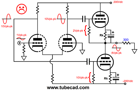
The long-tail phase splitter in this example provides a gain of ten, so the 1V peak-to-peak input signal becomes 10Vpk-pk at each output. The result is that the top triode sees a peak-to-peak grid-to-cathode signal of 2V, while the bottom output triode's grid sees 10Vpk-pk of signal, five times more. In the face of such a huge input signal, the bottom output triode slams off and then slams full on. The only thing to save the day and our ears is gobs of negative feedback. But why waste feedback on a problem that could have been fixed at the start? Imagine that you are driving a car whose right tires are over inflated, while its left tires are woefully under inflated. You could drive straight, but at the cost of constantly correcting for the intrinsic imbalance. Why? Fix the problem at its source and get back to important things, such as texting while you drive ;)
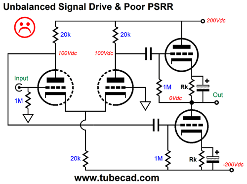
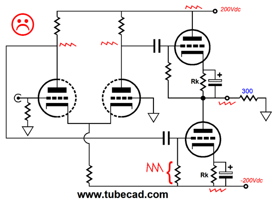
In terms of PSRR, things are not much better.
The bottom output triode's grid sees all of the positive power-supply rail ripple and all of the negative power-supply rail ripple. Ideally, the bottom output triode should see only the negative power-supply ripple at its grid and cathode, while the top output triode's grid should see no ripple at all. Let's now fix the drive imbalance.
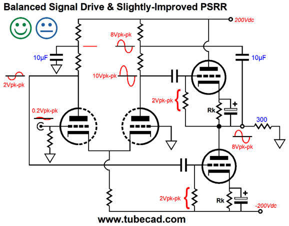
The 10µF capacitor on the right relays the amplifier's output signal to the top of the phase-splitter's right plate resistor. Note the five-fold reduction in input signal amplitude. The 0.2V input signal still get amplified by 10; as the right side of the phase splitter is bootstrapped to the output, the 2V of signal is added to the 8V of output signal. The left side of the phase-splitter is not bootstrapped, so its 2V of signal is delivered to the bottom output triode's grid. Both top and bottom output triodes sees the same amplitude of grid-to-cathode signal. Balance has been achieved. The next step is to improve the PSRR as well. Easy enough, as we need only terminate the left 10F capacitor to the negative power supply rail.
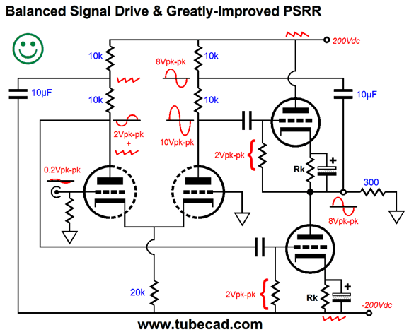
Are we there? No, as we can further improve the PSRR. We could replace the 20k cathode resistor with a constant-current source or we could use two resistors and a capacitor.
This is the best that we can achieve by careful design. But even this PSRR will worsen, once the output stage leaves the class-A window of operation. I call this phenomena "dynamically-induced noise." Just about all class-AB triode-based amplifiers are susceptible to it. The moral is, whenever possible, run class-A.
The Alternative
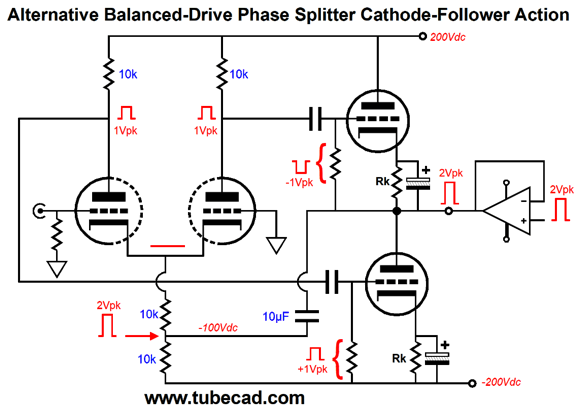
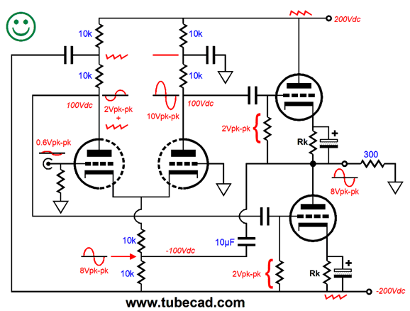
This time one 10µF capacitor attaches to the bottom of the long-tail phase splitter's 10k cathode resistor and to the OTL's output. The result is that 50% of the output signal gets superimposed upon the long-tail phase splitter's two plates. The halving of the output signal at the plates is critical, as no other ratio will work to balance the drive signals. Here is an example that illustrates how the output is back-fed into the long-tail phase splitter. We attach an external power amplifier that forces an 2Vpk positive pulse into the OTL's output.
The pulse then appears at the long-tail phase splitter plates, but at half the amplitude, i.e. 1Vpk. Since the top output triode's cathode was forced up by 2V and its grid only goes up 1V, the net result is a -1V pulse, which decreases the top triode's current conduction. In contrast, the bottom output triode's grid sees a 1V pulse, so its current conduction increases. Thus, both output triodes buck the pulse by the transconductance of the output triode used. Assuming a gm of 10mA/V, the 2V pulse will garner a 20mA counter response, which implies an output impedance of 100 ohms. The price we pay for effectively throwing away half of the output signal is that a higher input signal is needed and the raw output impedance is twice what it could be otherwise.
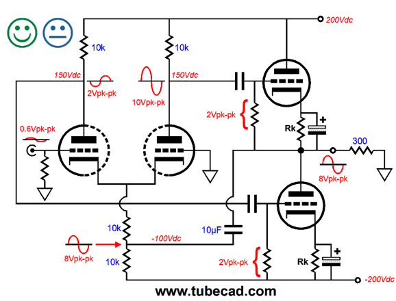
Note that 0.6V went in and 8V came out. Both output tubes still sees 2V of signal, but as only 4V of bootstrapping obtained, the long-tail phase splitter must generate 6V to create the 10V at the top output triode's grid and 2V at the bottom triode's grid. Why the ambivalent face? The PSRR is sub optimal in this circuit. Fortunately, the workaround is easy.
Note how the 10F capacitor served two purposes: it coupled the OTL's output to the phase splitter and it shielded the long-tail cathode resistor from the negative power-supply ripple. So, we ended up using three 10µF capacitor, not two, in this design. Moreover, we must provide more input signal into the phase splitter. Still, it is an interesting option. As I looked at the schematic, I wondered about injecting half of the output signal at the top of the phase-splitter plates instead. My first thoughts were crazy elaborate, using either added active parts or a center-tapped inductor. Then the simple way came to mind.
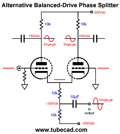
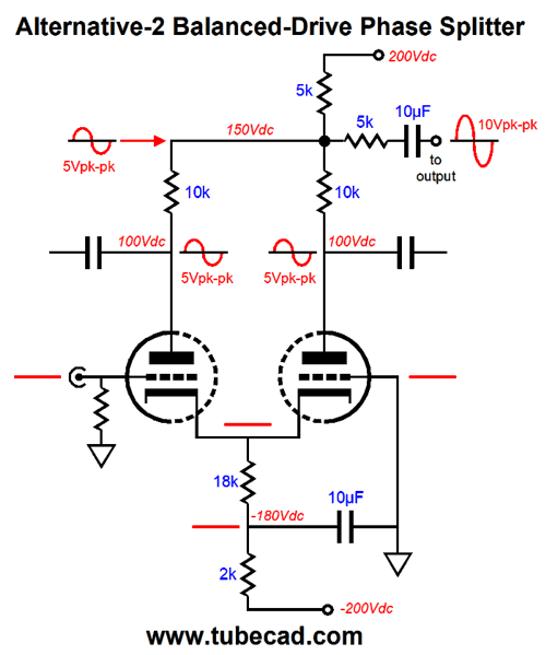
Alternative-2 Balanced-Drive
Because of the long-tail resistor being so high in value, the output impedance at each plate is staggeringly high; thus, almost zero PSRR. In some applications, this is a failing, but in this circuit it is an asset. The two 5k resistors nicely divide the output signal in half. Now, let's plug this phase splitter into an OTL amplifier and run the same forced-pulse experiment.
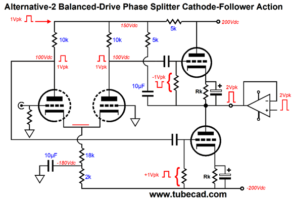
We end up with the same results as we got from the previous forced-pulse experiment: the output impedance equals 1/gm and both top and bottom triodes work equally to counter the pulse. Alas, the only way we can improve the PSRR is to forgo the use of a bipolar power supply.
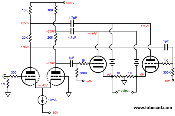
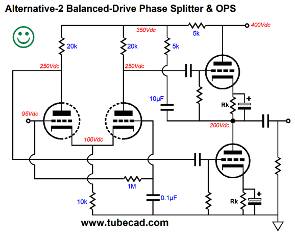
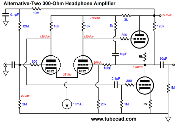
The output is capacitor coupled and the bottom triode sees no ripple at either its grid or cathode. Actually, whatever B+ ripple leaks into the circuit will be presented in phase and equal in magnitude tot he the tout triode grids, so it will tend to cancel at the output. Here is a practical design example: a tube headphone amplifier for 300-ohm headphones. The output tubes can be either another 6DJ8 or a 6H30 or 12BH7 or 5687 or ECC99...
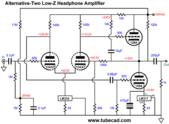
Note how the negative feedback loop is DC coupled to the output. Also note how only one internal coupling capacitor is used, as wee need a DC feedback loop to keep the output centered. Last note, the 120k resistor provides a DC current path from the B+ voltage to the feedback resistor string. No cathode-resistor bypass capacitor is used, as I think this OTL can get away without having to use them. The constant-current source can be made from either an LM334 or LM317 or something fancier. What if you own 50-ohm headphones? Well, something like the following can put out 60mA peak of current, which would develop 3Vpk across the 50-ohm load at its limit of class-A operation.
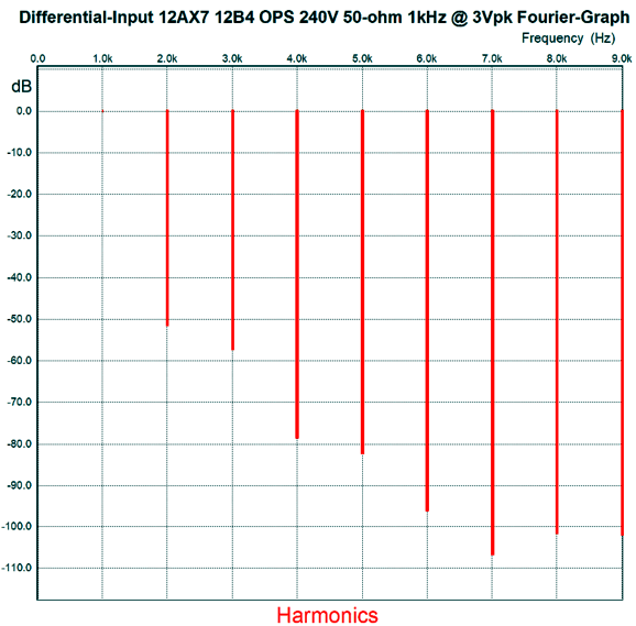
The 12B4 is a fun little single-triode tube that has been used in a Futterman OTL. The idle current through the output stage is 30mA, so each 12B4 will dissipate about 3.5W at idle. Here the result of a SPICE simulation.
About 0.3% THD, with a nice single-ended structure, no doubt that this headphone amplifier would sound quite sweet and warm. At 1Vpk at 1kHz, the THD was about 0.1%. The PSRR was good, but not great, coming in at about -38dB (most tube gear is far worse) and the output impedance was 15 ohms. The only big problem is finding a 200µF polypropylene-film coupling capacitor. If lower impedance headphones must be driven, then we could just add more 12B4 in parallel.
Okay, this is a tad embarrassing, but I thought that the harmonic structure looked a bit too single-ended for a push-pull amplifier. I ran some additional SPICE simulations and I found that the top output triode was working harder than the bottom triode. One possibility is that the 1M grid resistor is effectively in parallel with the 100k plate resistor, combing to form a 91k resistance, which is enough to create a 10% imbalance. I increased the 10k resistor that attaches to the 10µF capacitor to 12k and balanced was achieved, which was proved by a further reduction in 2nd harmonic distortion. So, why haven't I updated the schematic? I think the more single-ended harmonic structure might sound more pleasing. This would make a fine test for some enterprising reader, as none of the DC voltage voltage values are altered by this increase in resistance value; nor does the PSRR change, but the output impedance might fall by one ohm. Tubes are redeemed by both looking cool, or rather by looking warm, and by making listeners more emotionally pleased. Anything that makes me want to listen to more music is good. The man that I love to quote—Friedrich Nietzsche—put it so nicely, “Without music, life would be a mistake.”
//JRB
If you enjoyed reading this post from me, then you might consider becoming one of my patrons at Patreon.com.
User Guides for GlassWare Software
For those of you who still have old computers running Windows XP (32-bit) or any other Windows 32-bit OS, I have setup the download availability of my old old standards: Tube CAD, SE Amp CAD, and Audio Gadgets. The downloads are at the GlassWare-Yahoo store and the price is only $9.95 for each program. http://glass-ware.stores.yahoo.net/adsoffromgla.html So many have asked that I had to do it. WARNING: THESE THREE PROGRAMS WILL NOT RUN UNDER VISTA 64-Bit or WINDOWS 7 & 8 or any other 64-bit OS. I do plan on remaking all of these programs into 64-bit versions, but it will be a huge ordeal, as programming requires vast chunks of noise-free time, something very rare with children running about. Ideally, I would love to come out with versions that run on iPads and Android-OS tablets. //JRB |
John Gives
Special Thanks to the Special 67
I am truly stunned and appreciative of their support. In addition I want to thank
All of your support makes a big difference. I would love to arrive at the point where creating my posts was my top priority of the day, not something that I have to steal time from other obligations to do. The more support I get, the higher up these posts move up in deserving attention. Only those who have produced a technical white paper or written an article on electronics know just how much time and effort is required to produce one of my posts, as novel circuits must be created, SPICE simulations must be run, schematics must be drawn, and thousands of words must be written.
If you have been reading my posts, you know that my lifetime goal is reaching post number one thousand. I have 582 more to go. My second goal is to gather 1,000 patrons. I have 933 patrons to go. Help me get there.
Support the Tube CAD Journal & get an extremely powerful push-pull tube-amplifier simulator for TCJ Push-Pull Calculator
TCJ PPC Version 2 Improvements Rebuilt simulation engine *User definable
Download or CD ROM For more information, please visit our Web site : To purchase, please visit our Yahoo Store: |
|||


| www.tubecad.com Copyright © 1999-2018 GlassWare All Rights Reserved |