| John Broskie's Guide to Tube Circuit Analysis & Design |
30 June 2018 Post Number 430
Phase Splitter Ideas
The correct adjective for having two phases is "diphasic," but few know that it exist. "Diphase" and "diphasic" means consisting of two phases, as the OED puts it:
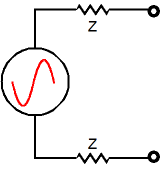
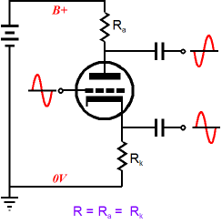
Where can we get a balanced signal? It might come from the signal source; for example, most stand-alone DACs now sport XLR output jacks in addition to the usual RCA jacks. On the other hand, most FM tuners, phono preamps, CD players, streaming-audio devices, old consumer tape decks… do not. With an unbalanced signal source, we must convert it to balanced by using a phase splitter, which is an unbalanced-to-balanced converter circuit. In the tube world, we have a few choices, such as the split-load phase splitter.
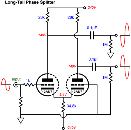
Another choice is the long-tailed differential amplifier, whose two inputs see different signals, one receiving the input signal, while the other is AC grounded.
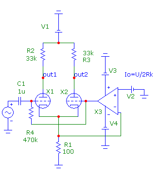
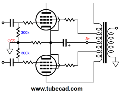
Improvements to this circuit usually take two forms: replace the shared cathode resistor with a constant-current source and fiddle with the plate resistors values to improve the balance. One variation this topology that I have seen before and which Russian reader, Alexey, has sent on to me is the following design. The idea is to use an OpAmp to establish balanced output.
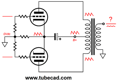
The OpAmp strives to establish no signal at the coupled cathodes, as the OpAmp's non-inverting input is grounded. The OpAmp performs double duty, as it not only establishes balanced output, but also coerces the desired idle current flow by setting the required DC grid voltage for the triodes. If you do not like the input coupling capacitor, the topology can be rearranged.
Now, the coupled cathodes can seek their needed DC voltage on their own, while the OpAmp's inverting input still sees all the AC signal present on the cathodes and the OpAmp's output is ground referenced. How this hybrid phase splitter works is simple enough: the OpAmp will uses all its open-loop gain and all its negative feedback to keep its two inputs at the same voltage. Since the non-inverting input is grounded, its inverting input must be brought in line. The only way that no AC signal will appear at the coupled cathodes is if the two triodes are responding to the input signal in anti-current phase, as that way both current flows will sum to the idle value. And the only way that the right triode can respond to the input signal in anti-current phase is if its grid sees an inversion of the input signal, which the OpAmp will strive to do. The mental stumbling block many might encounter is the seeming paradox of the OpAmp establishing zero signal on the coupled cathodes, but nonetheless creating the needed anti-phase signal for the right triode, ostensibly without an input signal, looking something like electronic ESP. The paradox is dissolved when we realize just how much open-loop gain the average OpAmp achieves. For example, the much-loved OPA627 runs an open-loop gain of 120dB, which translates into 1 to 1,000,000. In other words, the signal present on the coupled cathodes need only be 1/1,000,000 as big as appears at the left triode's grid. Okay, what are we to make of this design. It will work, true enough, but is the best use of the OpAmp? Once we decided to go hybrid, we should try to get the most out that move as we can. For example, why not use the OpAmp to create the inverted input signal directly, rather than indirectly?
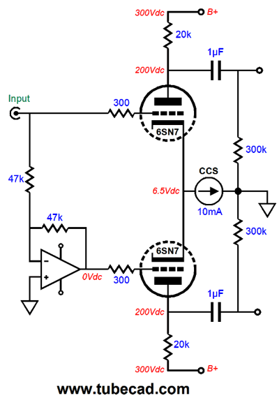
In the schematic above, we see the OpAmp configured as an inverting amplifier. No matter what the signal source's output impedance is, this inverting amplifier will produce an equal amplitude but inverted copy of the signal. To better the performance, we can replace the shared cathode resistor with constant-current source.
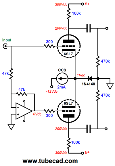
In fact, as the OpAmp will need a negative power-supply rail, we can terminate the constant-current source into the -12V power-supply rail, rather ground, which would allow us to use a high-mu double triode, such as the 6SL7 or 12AX7 that might otherwise voltage starve the solid-state constant-current source.
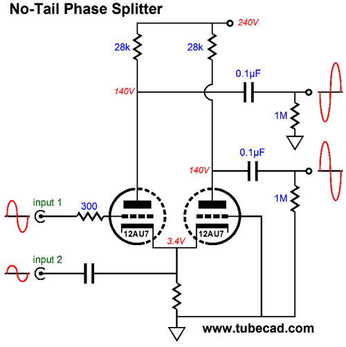
The added diode is there to protect the 6SL7 at startup, when its cathode is cold. In other words, its two grids will not be 12 volts more positive than its cathodes at startup. An other possibility is to use the single OpAmp to drive the coupled cathodes in what I call the No-Tail Phase Splitter.
This topology got full coverage in post 294. (By the way, posts 294 and post 295 are two of my best. I just looked over them and I was made proud. My aim is to create posts that I wish I could have read 40 years ago. Well, those two would have been at the top of my reading list.) Two possibilities immediately come to mind. The first uses a two-resistor voltage divider to halve the input signal and then capacitor couple to the cathodes; the 6.49k cathode resistor allows a current path to the negative power-supply rail.
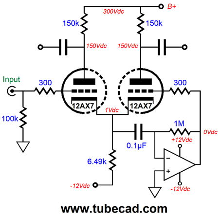
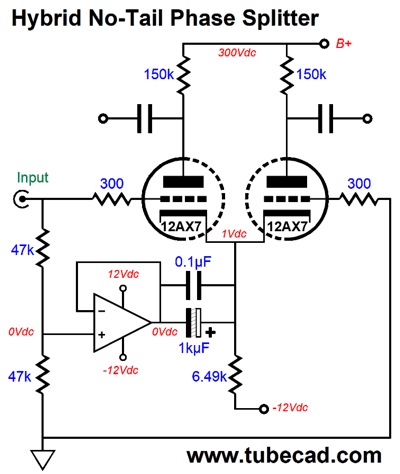
(Now that I look at the schematic above, I would replace the polarized electrolytic with a non-polarized electrolytic type.) Or, rather than hassle with large-valued capacitors, we can place the coupling capacitor before the OpAmp and directly couple the OpAmp to the cathodes.
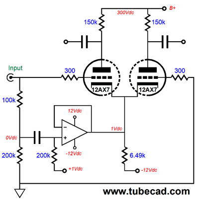
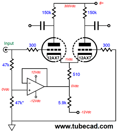
Note that the two 200k resistors are, in AC terms, in parallel, so result in a 100k impedance, so the OpAmp sees 50% of the input signal. One potential problem with this circuit is that we might get the required cathode voltage wrong. In other words, I prefer to let a cathode resistor or constant-current source to set the needed cathode voltage. In fact, we can directly couple the OpAmp and use a secondary cathode resistor.
The OpAmp's output is at ground potential, so as far as the two triodes are concerned, there is only the 510-ohm cathode resistor. The bottom 47k resistor gets the asterisk, as its value might have to be fiddled with, depending on the triode used. A triode's cathode offers a slightly higher amplification factor (mu) than its grid. How much more? mu' = mu + 1 Thus, with a high-mu triode, such as the 12AX7, we can assume the same mu for both the grid and cathode; but with a medium-mu triode, such as the 6SN7 or 12AU7, we must do the math. The result will be that the 47k resistor will need to be replaced by slightly lower value, say 45.3k.
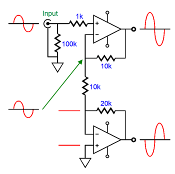
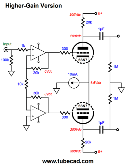
OpAmp-Based Phase Splitter
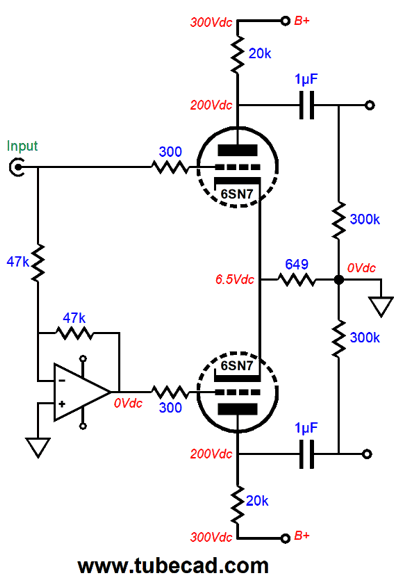
This circuit accepts an unbalanced input signal and delivers a balanced pair of output signals. As configured, the phase splitter realizes a gain of 2 or +6dB. In other words, 1Vpk of input signal will provoke 2Vpk of balanced output or 4Vpk-to-pk of signal. Next, we need a pair of triodes to provide additional gain and some tube mojo.
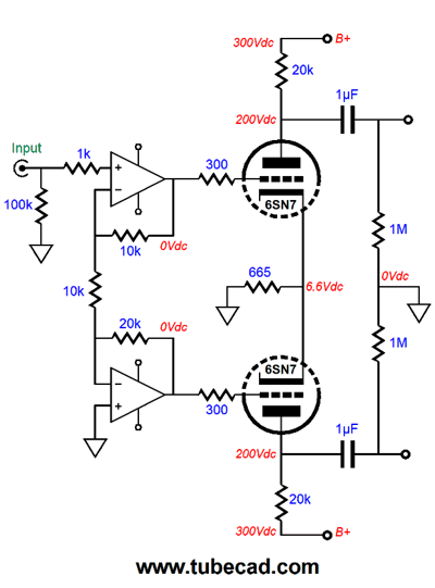
The two 6SN7 triodes provide a gain of 10 or +20dB. If even more gain is needed, we can bump up the gain from the OpAmps.
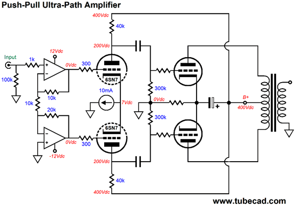
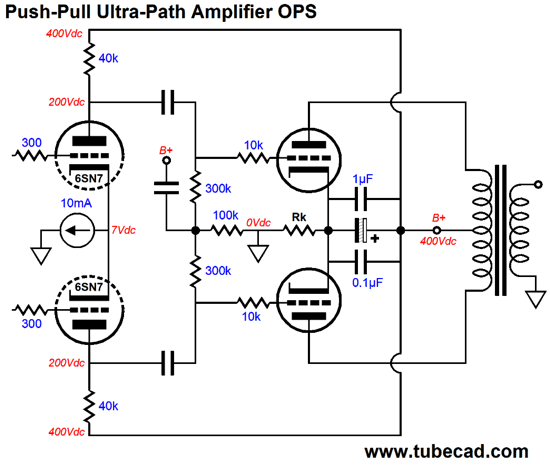
The OpAmp-based phase splitter now provides a gain of 3 (+9.5dB). More is certainly possible, but we risk diminishing tube mojo. This solid-state phase splitter with gain allows to create the following ultra-path design.
The 6SN7 differential amplifier delivers a good amount of gain (17), but a very poor PSRR, almost none. Normally, this would prove a liability, but not in this amplifier, where it has become an asset. The two output triodes see 100% of the power-supply noise at both there cathodes and plates and almost 100% of the power-supply noise at their grids. The result is that the power-supply noise becomes nearly invisible to the output triodes, much like the 400MPH air speed aboard a jet is not felt by the bored passengers sitting in their seats; as far as they are concerned, they are not moving.
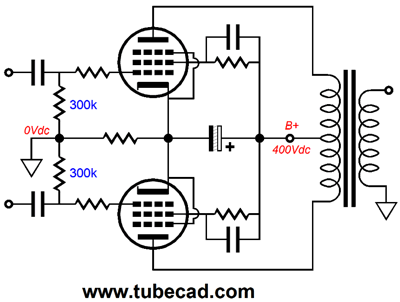
If pentode, such as the EL34 or KT88, are more to your liking, then the following arrangement is the way to go.
Note that the screen capacitors terminate into the B+ connection, not ground. If you prefer ultra-linear, then noting stops you from doing this.
What happens if the driver stage offers a clean output with no power-supply noise?
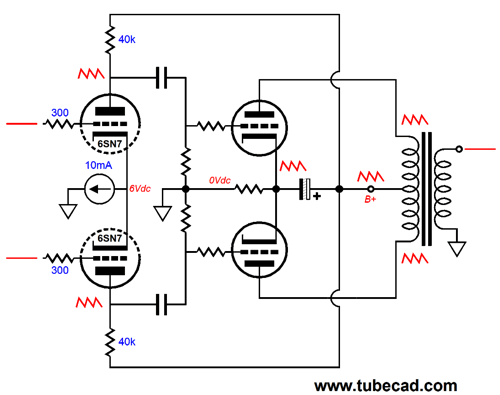
The answer depends. It depends on whether the amplifier is at idle with no music playing. In this case, the output transformer should reject power-supply noise, as it appears as a common-mode signal to it. The same holds true as long as the output stage operates in its class-A window of operation. But what happens, however, once one output tube cuts off completely? The power-supply noise is no longer common-mode and becomes a signal to pass on to the loudspeaker. I call this dynamically-induced power-supply noise and I believe it helps explains the increase in coarseness of sonic presentation, as the amplifier pushed hard, but still far below its rated output. Returning to the ultra-path design, getting to 100% power-supply noise at the grids can be done, as shown below.
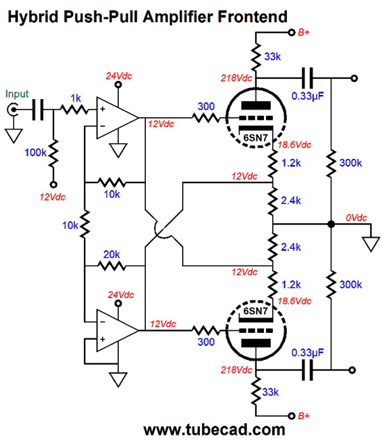
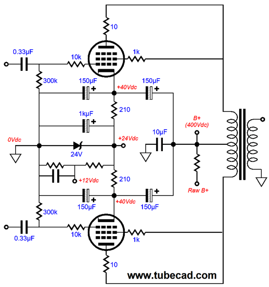
Now, the grids, cathodes, and plates all see 100% of the power-supply noise. A further improvement would be to replace the cathode resistor (Rk) with a constant current source, which would be shunted by a zener whose break voltage is a tad higher than the idle cathode voltage. As everyone is warmed up now and mentally limber, why not look into a 50% solution, where 50% of the power-supply noise is injected at cathodes and grid, but the plates see 100% of it? Let's start with the amplifier frontend.
The OpAmps cross-couple drive both the grids and cathodes, which effectively doubles the gain from the OpAmp phase splitter. The 1.2k cathode resistors were especially chosen to result in a PSRR of -6dB or 0.5 at the 6SN7 plates. Now, we have to find a way to inject 50% of the power-supply noise at the output tube cathodes.
Equal-valued capacitors is the easy way to go. The bottom 150µF capacitors need only be rated for 50V, whereas the top 150µF capacitors should be rated for at east 400V, preferably 450V. Why the over-rating? Tube power amplifiers are notorious for having variable B+ voltages. At start-up, all the tubes are cold and not conducting, but the B+ voltage is building in fraction of a second. In addition, the power transformer's secondary is saddled with a high DCR. Combine the cold tubes with a high DCR and no real current draw and you get much higher B+ voltage than will obtain once the amplifier is warmed up. Note the 24V zener. Why is it there? We need to power the OpAmps and since the output stage is cathode biased, we might as well steal some of that wasted cathode voltage. Why were two cathode resistor used instead of one? They ensure better current balance between output tubes than one would. In addition, if one output tube is missing from its socket or it heater element opens, the other is not troubled by it. In contrast, with one cathode resistor, the remaining output tube would see too high an idle current. Okay, let's put it altogether.
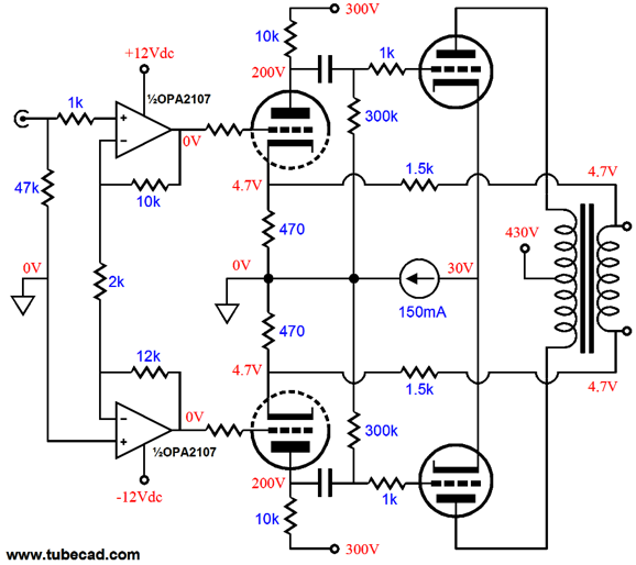
Click on schematic to see closeup The output pentodes are being run in triode-connected mode. Is this important? It is if no negative feedback loop is included. One way to look at it is that triodes come pre-negative-feedback-laden, as they present plate resistance, which will result in a lower output impedance. To see more push-pull amplifier designs based on the OpAmp phase splitter frontend, such as the following, check out post 304.
This time the solid-state phase splitter provides a gain of 6, so 1Vpk comes out as +6Vpk and -6Vpk. The higher gain is needed as two negative feedback loops reduce the tube amplifier's gain. Next time, I will show how we can further take advantage of the solid-state phase splitter in a hybrid tube amplifier.
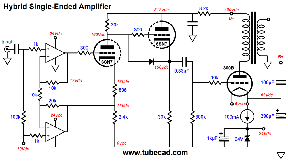
Single-Ended Hybrid Amplifier
Click on schematic to see closeup The left 6SN7 triode is driven at both its grid and cathode, which results in twice the gain. (If slightly more gain is needed, we can alter the OpAmp resistors.) The 300B output tube gets the Aikido-mojo treatment.
See post 229 for more details. Note the 24V zener in the previous schematic. Wy is it there? For the same reason it was used i the push-pull designs: we need to power the OpAmps and since the output stage is cathode biased, we might as well steal some of that wasted cathode voltage. Also note that no negative power-supply rail is used. Well, we could create one if we wished.
Floating Power Supplies
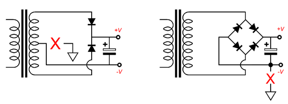
I know solder-slingers who insist on grounding the power transformer secondary center tap—no matter what I say. So deeply ingrained is the practice that they cannot summon the imagination to envision it being any other way, alas.
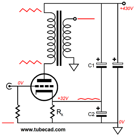
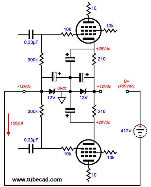
For the rest of us, it is no big deal; we simply do not ground the center tap, which allows us to build the following power supply.
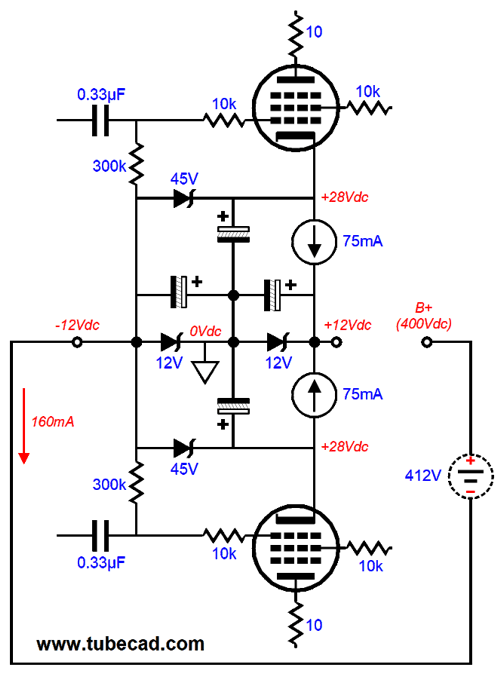
The two 12V zeners are used to create the +/-12V power-supply rails for the OpAmp phase splitter. The circuit holds a ground, but the floating power supply does not directly attach to it, hence it floats, albeit at a fixed -12V from ground potential. Note that if the output tubes are missing from their sockets, no +/-12V rail voltage develop. We could attach a high-wattage, high-valued resistor from the top of the zener string to the B+ connection, which would allow some current to flow in spite of missing output tubes. We could replace the cathode resistors with constant-current sources, but that would would best with a class-A output stage. If we wish to run a cooler class-AB, then the following is possible. The 45V zeners act as voltage clamps. At idle, they only see a 40V differential, but as the output stage gets banged about by loud playback, the capacitors shunting the constant-current source will charge up until the zener break voltage is reached.
Music Recommendation: Sylvie Courvoisier And I remember finding European jazz albums stocked in the New-Age or Meditation-Music bins, as the record store employees didn't know what genre the albums belonged in. Not lost, the European jazz musicians simply went off on different trails. For many, European classical music showed a fruitful path. For others, their own native folk songs and musical traditions led the way. Jazz is radically different from other music genres in that it is performer centric. Not matter how inspired the classical conductor or gifted the soloist, we still give most of the credit to the composer. With jazz, it's just the opposite: the original seed music, be it a song from the Great American Songbook or some silly jingle from TV commercial, is nowhere as important as what the jazz musician does with it. Think of jazz as a musical recycling project. If you go to the concert hall to hear your favorite symphony and then return the next night to hear it again, you will hear it again. The second performance might be a tad more exciting or a tad less so, but it will be note-for-note the same performance. Not so with jazz performances. I have sat sat in for two sets, one after the other, which supposedly held the same list of songs, but which sounded dramatically, wildly different. Recording engineers used to bemoan the incredible inconsistency in performing times for the same song, as the recorded performance might and probably would depart from the rehearsal performance.
Sylvie Courvoisier is a Swiss jazz pianist who has spent decades in the USA, performing with the greats of the American jazz scene. Yet, she definitely belongs in the European jazz grouping, as her music leans heavily on the European classical tradition. This doesn't mean that her music is stodgy, far from it, as she exhibits a strong experimental, avant-garde streak. For example, she like the Canadian pianist, Paul Bley, will pluck the strings of her piano in a performance. Tidal offers sixteen of her albums. I haven't heard them all—not yet. I recommend her recent D'Agala album as a starting point. Why? It is an interesting artistic endeavor and it shows off your stereo well. Try the second track, Bourgeois's Spider, and crank the volume up. But be sure to listen to the entire album, as it offers so many delightful surprises. //JRB
If you enjoyed reading this post from me, then you might consider becoming one of my patrons at Patreon.com
User Guides for GlassWare Software
For those of you who still have old computers running Windows XP (32-bit) or any other Windows 32-bit OS, I have setup the download availability of my old old standards: Tube CAD, SE Amp CAD, and Audio Gadgets. The downloads are at the GlassWare-Yahoo store and the price is only $9.95 for each program. http://glass-ware.stores.yahoo.net/adsoffromgla.html So many have asked that I had to do it. WARNING: THESE THREE PROGRAMS WILL NOT RUN UNDER VISTA 64-Bit or WINDOWS 7 & 8 or any other 64-bit OS. I do plan on remaking all of these programs into 64-bit versions, but it will be a huge ordeal, as programming requires vast chunks of noise-free time, something very rare with children running about. Ideally, I would love to come out with versions that run on iPads and Android-OS tablets. //JRB |
John Gives
Special Thanks to the Special 67
I am truly stunned and appreciative of their support. In addition I want to thank
All of your support makes a big difference. I would love to arrive at the point where creating my posts was my top priority of the day, not something that I have to steal time from other obligations to do. The more support I get, the higher up these posts move up in deserving attention. Only those who have produced a technical white paper or written an article on electronics know just how much time and effort is required to produce one of my posts, as novel circuits must be created, SPICE simulations must be run, schematics must be drawn, and thousands of words must be written.
If you have been reading my posts, you know that my lifetime goal is reaching post number one thousand. I have 570 more to go. My second goal is to gather 1,000 patrons. I have 933 patrons to go. Help me get there.
Support the Tube CAD Journal & get an extremely powerful push-pull tube-amplifier simulator for TCJ Push-Pull Calculator
TCJ PPC Version 2 Improvements Rebuilt simulation engine *User definable
Download or CD ROM For more information, please visit our Web site : To purchase, please visit our Yahoo Store: |
|||

 versus


.png)


| www.tubecad.com Copyright © 1999-2018 GlassWare All Rights Reserved |