| John Broskie's Guide to Tube Circuit Analysis & Design |
|
9 July 2018 Post 431
More Circlotron A quick recap of the circlotron's features: the same output device is used throughout, be it a triode or pentode or NPN or PNP transistor or N-channel or P-channel MOSFET, which nicely sidesteps the problem of using dissimilar output devices, such as NPN and PNP transistors; second, both output devices see the input signal amplitude, unlike a totem-pole arrangement that uses the same output devices, top and bottom, but must deliver dissimilar signal amplitudes, as the top device will need to see a far larger input signal than the bottom device.
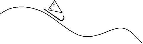
The circlotron's liabilities are that few understand how it works and it requires two floating power supplies per channel. In contrast, everyone believes that he knows how a conventional, transformer-coupled, push-pull tube amplifier works, even in the absence of any supporting evidence; and the conventional amplifiers can use a single fixed power supply between two or more channels. Both the conventional, transformer-coupled and circlotron amplifiers, however, face the same class-A problem. What is the class-A problem? Above in heaven, all amplifiers run in class-A. Down in hell, all amplifiers run in class-C. On Earth, where I happen to reside, most amplifiers, as in 97%, run in class-AB or class-B, with the remaining 3% to be divided by class-A and class-D amplifiers, with class-D getting the bigger slice. Eventually, class-D will become the standard, especially when the EU and the USA get around to outlawing any other type of amplifier. In The States, this new law will be labeled the Polar-Bear Preservation Act. When 300Bs are outlawed, only outlaws will own 300Bs. What makes class-A so wonderful is that it offers the lowest distortion and most consistent output impedance, and it is the easiest to auto-bias. Its down side is heat, heft, and hardly cheap. Massive heatsinks and fat power transformers are neither cheap nor light. And building a chassis sufficiently robust to hold these items also entails great expense and weight, and great weight implies huge shipping costs. In contrast, a 100W class-D amplifier can rest on the palm on your hand, with neither pain to your hand nor to your wallet. So, until they get around to passing the Polar-Bear Preservation Act, we are stuck with class-AB, which in turn means that we are stuck with gm-doubling and critical-biasing nightmares. The circlotron does not sidestep this problem, as few—if any—circlotron power amplifiers run in true class-A, popular conceptions to the contrary. One solution, which is made possible by digital music file storage, is to vary either the idle current or the power-supply rail voltages or both to meet the expected musical demands—dynamically, as the music plays. Digital playback is dead, which is a good thing, as live playback, such as live performances or LP playback or radio playback is uncertain. Imagine that you watched the TV game show, Jeopardy, in the afternoon, then again with friends at night, with the same episode playing both times. How your friends would marvel at your knowing the answers to all the most difficult questions, such as the average yearly rain fall in Mongolia. It's easy, if you already know the answers. Well, with a digital file, we already know the answer, i.e. what is coming our way. I mentioned this setup before, rakishly calling it Sledding Bias. A good example of what I have said on this topic might be post 361.
The idea is simple: we do not want to react, but to anticipate the demands that will be made upon the power amplifier. One possible implementation would be that the power amplifier would hold its own DAC and would implement a 2 second delay, which would allow the amplifier enough time to vary B+ voltage to meet required voltage swings. Or, it could run a constant B+ voltage and vary the idle current or it could vary both the B+ voltage and the idle current. With such a scheme, we could get 200W class-A power amplifiers that didn't cost a fortune or weigh more than you do.
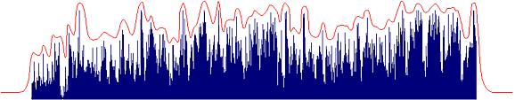
Most digital music file formats include the ability to embed an image within the file. This image could further embed the peak-demand profile of the file's music content. With such information, the 2-second delay would not be needed. Well, I can dream, can't I?
Imagine a class-A, push-pull, power amplifier that idled at 1A. Such an amplifier could deliver into an 8-ohm load 16W (or 2A peak) and still remain within its class-A window of operation. Now, 2A against 8 ohms results in a peak voltage swing of 16V, so the amplifier's power-supply rails need only be +/-20Vdc. We multiply the 1A idle current against 40V (the combined total of +/-20Vdc) and we get 40W of dissipation per channel. To find the amplifier's efficiency you divide 16W by 40W and get 40%, which is close to the theoretical limit of 50%. Imagine a class-A/class-G, push-pull, power amplifier that idled at 1A, but held +/-10V and +/-20V power-supply rails. Such an amplifier would still deliver 16W into 8-ohm loads, but would only dissipate 20W per channel at idle. Sneaky, no? Now imagine different power-supply rail voltages, say +/-10V and +/-30V and an idle current flow of 1.5A. Such a class-G amplifier could deliver 24Vpk voltage swings and 3A current swings into an 8-ohm load, resulting in 36W of output power, but only dissipate 30W per channel. Back in post 250, I showed how a class-G circlotron power amplifier could be created.
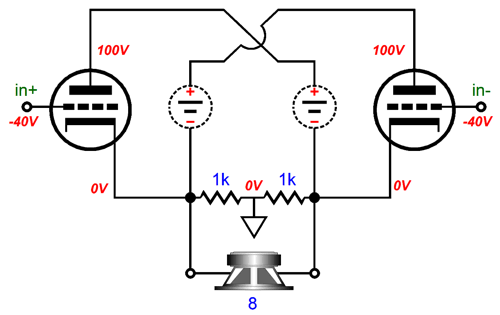
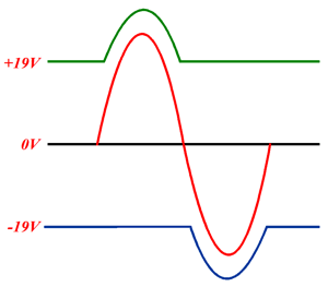
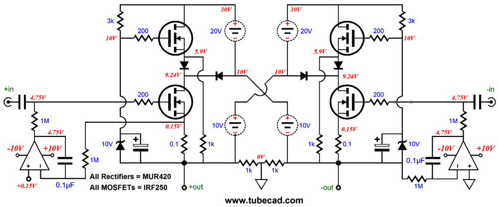
This amplifier's output stage uses N-channel MOSFETs throughout. Vacuum tubes could be used, say 6AS7 triodes on the bottom, with EL509 pentodes on top, but let's stick with the cheap, lower-voltage devices, as that will make the explanation of the circuit's workings easier, if for no other reason that we will not have to deal with negative grid-bias voltages. The top MOSFETs are not completely cutoff, as they still draw a trickle current through the 1k source resistors. As the input signal swings upwards, the top MOSFET will engage, pulling up the rail voltage for the MOSFET below it, allowing the bottom MOSFET to swing far larger output voltage swings. As the top MOSFET absorbs the job of delivering voltage to the bottom MOSFET, the top MOSFET will go from a trickle of current flow to a mad torrent of current flow. For example, let's say that the top MOSFET switches in as the loudspeaker sees 8Vpk and 1Apk positive swings (4W of power); with a rich idle current of 1.5A and the half of the added 1A current flow coming from the bottom MOSFET, the top MOSFET will see its current increase to 2A. At the same time, top MOSFET sees a much bigger source-to-drain voltage than the bottom MOSFET. In other words, at the transition point, the top MOSFET will dissipate far more heat than the bottom MOSFET. Fortunately, most music will comfortable fit in the 4W window, with only brief excursions outside this wattage window. On the other hand, if you are playing organ music or electronic synthesizer music, the top MOSFETs might get too hot. I have a workaround, but first let's look into how we could make a floating power supply for this class-G/class-A circlotron.
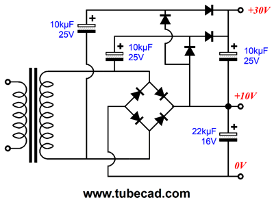
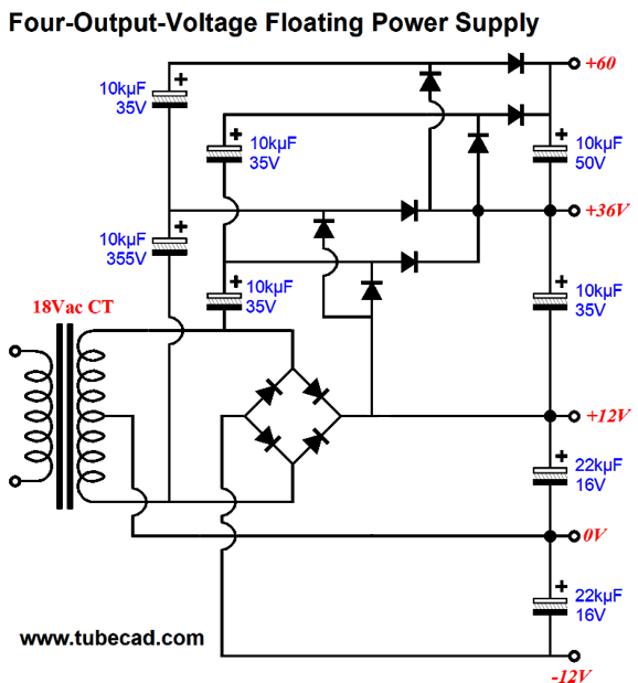
The transformer's secondary voltage is a low 7Vac, which directly rectifies up to about 10Vdc, depending on the rectifiers used. The 10µF capacitors all charge up to about 20Vdc, which explains how the +30V power-supply rail voltage is created. Now, let's look at the complete power supply for one channel.
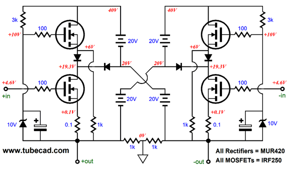
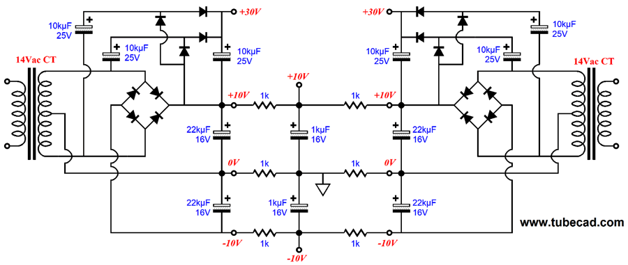
Note that only one center-tapped secondary is needed per side, in spite of the three output voltages (four output voltages, if we include 0V). The negative 10V power-supply rail is needed for creating a power supply for the OpAmps that will be used to auto-bias the output stage and eliminate a DC offset. how both sides meet through six 1k resistors. The center of each pair of 1k resistors is like the center of a teeter-totter, as they do not move off their idle voltages. Think about it: as one output move down in voltage, the other output moves up in voltage—equally. So, if the positive output swings up 10V, the negative output will swing down -10V; thus, the center resistors see 0V at their junction. So, too, the top and bottom pairs still see +10V and -10V at their junctions, as the center voltage of +20V and 0V is +10V, just the center voltage of 0V and -20V is -10V. I mentioned auto-bias and DC servo circuits, so I might as well show them in the output stage. Here is the complete schematic.
The OpAmp on the left set the idle current, as it monitors the voltage drop across the source 0.1-ohm resistor. The OpAmp on the right is configured as a DC servo, which monitors the DC voltage at the negative output. With both in place, the both the DC offset and idle current for both bottom MOSFETs are taken care of at once. In other words, we do not need to use four OpAmps per channel. Okay, what if we want more power? We could bump up the secondary rail voltage from 30V to 60V, which might yield close to 200W of power. The only problem with this approach is that the top MOSFET will see a huge current flow as they are brought into play. For example, 7A of peak current results in 196W into 8-ohm loads. Class-A operation demands an idle current flow of at least 3.5A, so the top MOSFETs will face at least this much current and have to withstand a nearly 50V of voltage differential from source to drain, which implies an instantaneous dissipation of about 200W. Not good.
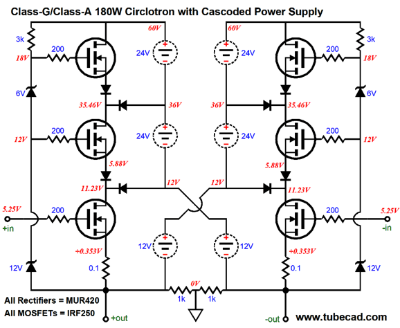
Class-G² Circlotron
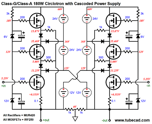
This is the simplified version for the sake of clarity. The two outputs drive the zeners along with powering the speaker. As the output swings beyond the ability of the two floating 12V power supplies to deliver the needed voltage, the next set of floating rail voltage kick in, then the next set as these run out of voltage. Here is the more complete version.
All the MOSFETs are the same type. The IFRP250 is an old part and the IRFP260 is probably a better choice. The bottom MOSFEts idle at a crazy high 3.5A, which will allow 7A peaks of current flow within the class-A window of operation. In SPICE simulations, the output cleanly extend to 54Vpk, with a THD of 0.15% and 182W into 8-ohm loads. At 1W of output, the THD was 0.03%. The bottom MOSFET run super hot, at 38W of dissipation at idle, while the remaining four MOSFETs run cool at idle. A better setup might be to use four bottom MOSFETs instead of just two, each getting its own 0.2-ohm source resistor.
Developing the four rail voltages is only a bit more complex than what we saw earlier.
The 12 rectifiers and the eight capacitors develop the needed voltage.
More Solid-State Phase Splitters
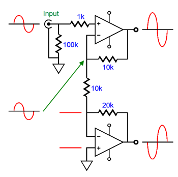
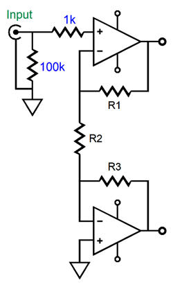
The circuit above offers a gain of 2 (+6dB). If 1V is presented to the top OpAmp, its output will be +2V, while the bottom OpAmp's output will be -2V. what if we want more gain? The following table list various gains and the set of resistor values needed.
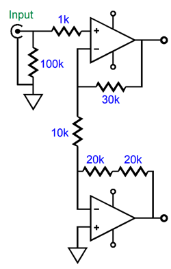
The odd gain setting is 4 (+12dB), as it seems that no combination of readily available 1% resistor values (E96 values) can deliver exactly a gain of 4. If we are willing to use two resistor to make R3, then we can easily get to exactly 4.
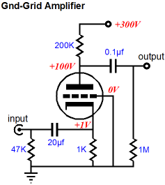
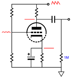
Beyond the OpAmp's availability to deliver exact gains, which is close to impossible with a long-tailed phase splitter based on triodes, the OpAmp offer a low output impedance and the ability to drive fairly low-impedance loads, which is why they are so often used in headphone amplifiers. Are these valuable features in this application? It depends. For example, we could chose to drive the cathodes rather than the grid of the following differential amplifier, which would sidestep the problem of Miller-effect capacitance. This arrangement is called a grounded-grid amplifier, as the input is taken at the cathode and the grid terminates into ground.
Well, here is our chance to sneak some Aikido mojo into the circuit. What if rather than grounding the grids, we feed them a portion of the power-supply noise? Why? Because if we do the math right we can create a power-supply null at the grounded-grid amplifier output.
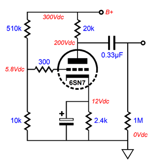
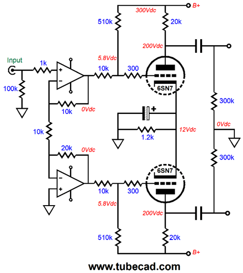
The small sampling of power-supply noise presented to the grid gets both amplified and inverted at the triode's plate, which then nulls the power-supply noise that would otherwise be present. With a 6SN7, the following part values worked in SPICE simulations to create the power-supply noise null.
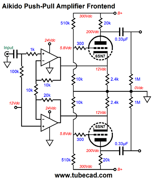
Now all we need to do is to make a balanced version.
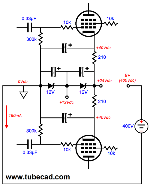
Note the input coupling capacitor and the OpAmps only requiring a positive power-supply rail voltage and no negative rail voltage, as ground potential effectively becomes a negative power-supply rail voltage. In my last post, I showed how a floating power supply could be used to create a negative power-supply rail voltage. Here is how we could create the single positive power-supply rail voltage of +24V.
Instead of two 12V zeners, a single 24V zener could be used and two 1k resistor in series could be used to deliver the +12V reference voltage. Another way to introduce some Aikido mojo would be to mix some of the power-supply noise with the output from the solid-state phase splitter, as shown below.
The OpAmp should have zero problem delivering the steady 0.58mA current flow through the 520k worth of resistance before hitting the B+ voltage. In fact, think of these resistors functioning as single-ended pull up resistors. Okay, let's flesh out the design.
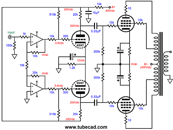
Note that the OpAmp is DC coupled at its input, so a 12V negative power-supply rail voltage will be needed. Also note how the shared cathode resistor is bypassed by a large-valued capacitor. This capacitor is essential. Without it, a much larger portion of the power-supply noise would have to be presented to the grids. The pentode output tubes are configured in the ultra-linear arrangement and each plate gets its own 10-ohm plate-stopper resistor. Cathode bias is used, with each cathode resistor being bypass capacitor. If you are the bold type, then you can try the following variation on the left, which AC couples the the two cathodes, but leaves the cathode resistor unbypassed.
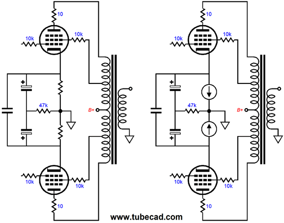
Effectively in AC terms, the two cathode resistors are in parallel with each other, acting as a single resistance to ground. In DC terms, each cathode resistor is separate and allows each output tube to cathode bias on its own. The 47k resistor is there only to provide a DC path to ground, which allows the two large-valued electrolytic capacitors to charge up. Now, if we are willing to run a true class-A output stage, we can use the arrangement on the right. Each output tube will draw the same current and find its own required cathode-to-grid voltage. Matched output tubes are seldom as matched as we would like and they may not stay matched over their lifetimes, so this auto-bias arrangement is an excellent workaround. The price we pay is class-A operation. If this is too high a price, we could shunt each constant-current source with a zener, whose break voltage is purposely set a few volts higher than the normal cathode voltage. For example, if the typical cathode voltage is 26Vdc for our output tube, the zener break voltage could be 30V. This is kludge of a workaround, not an ideal solution. Nonetheless, the zener will only engage at high power output, so the transition effects will be less noticeable.
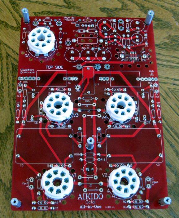
Sneak Peek of New PCB
The sockets must be attached to the top of the PCB. (About once a year, I get a regretful email from a customer who soldered them to the bottom side.)
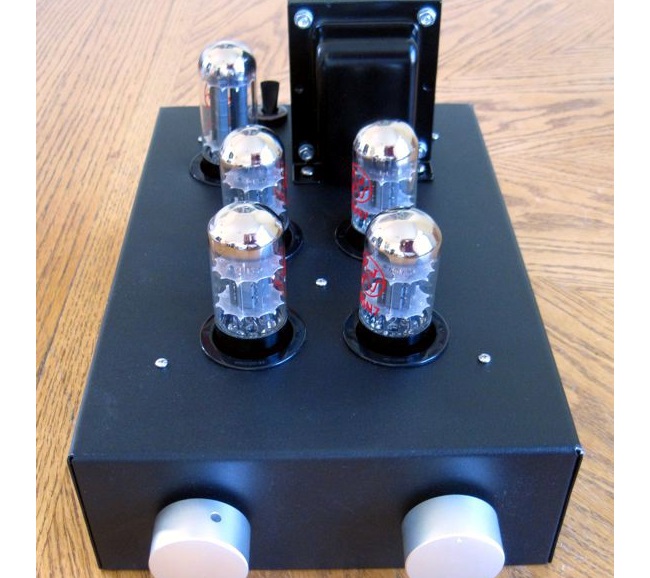
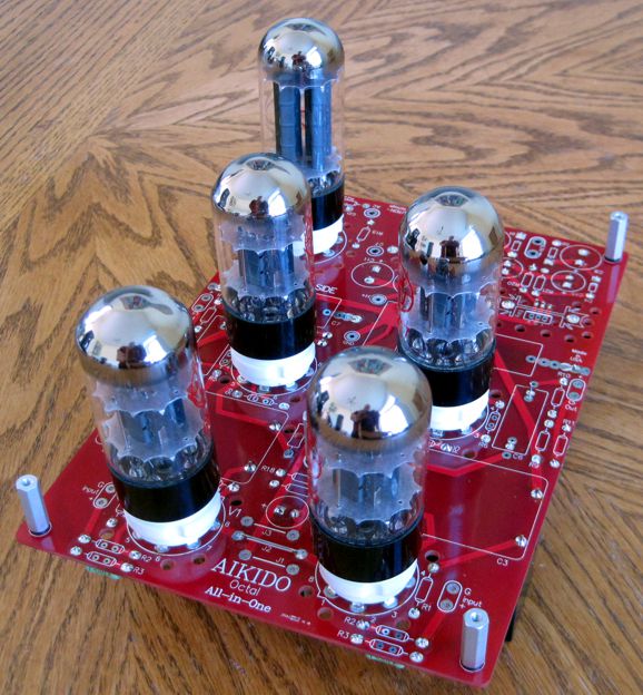
Here is the PCB with the tubes (all JJ types) in socket.
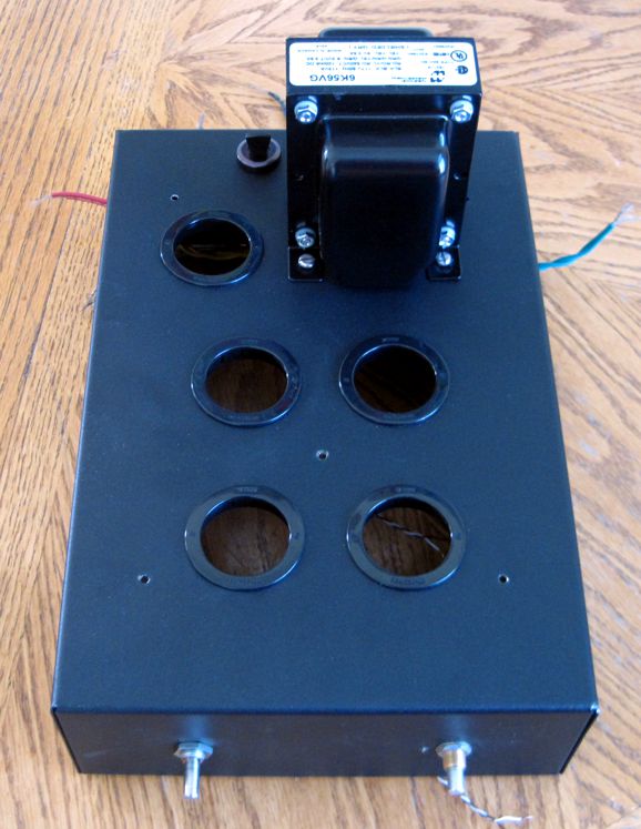
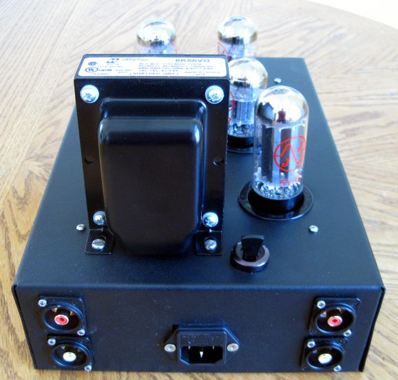
The chassis is a Hammond steel box that is 3in tall and 8in wide and 13in deep.
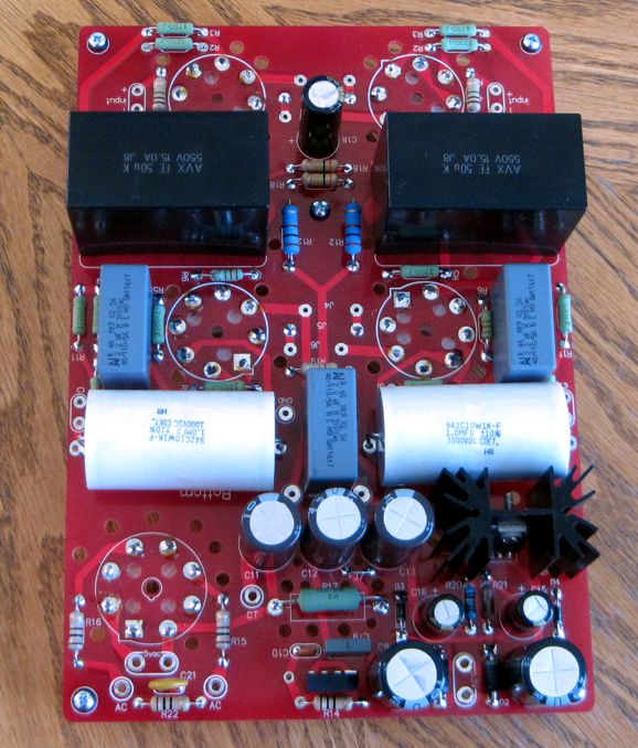
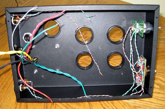
Here is the box's insides. The volume control is a 50k stepped attenuator fro Goldpoint and the other PCB is one of my Tilt-2 circuits.
Here is the rear of the box. Note the fancy RCA jacks.
The power switch is at the back of the chassis. Why are there only one set of inputs and one set of outputs? I wanted to keep this project simple and I just didn't have enough room to add more RCA jacks and an input selector switch. In general, I listen to one input, say just LPs or just DAC, for a week or more, so manually switching signal sources will not be that big a deal. How does it sound? Wonderful. I finished it this morning. I was in such a hurry that I stupidly just plugged it into my system, rather than follow usual procedure of using a variac and slowly bringing up the wall voltage with no tubes, other than the 5Y3 rectifier, in their sockets, measuring al the critical voltages along the way. I was in a big hurry, however, as it would be a long week before I could get to it again. Fortunately, nothing went wrong. No thumps, pops, or squeals. In fact, it went quite well, thank you very much. I listened to variety of music and I was pleased. When I return, I will dig out my $$$ NOS tubes and give some further listening. As this project develops further, I post the results.
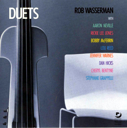
Music Recommendations, Rob Wasserman
Alas, Tidal does not offer this album, but they do offer his earlier album, Solo, (1983) which is definitely worth listening to.
Happy listening. //JRB
User Guides for GlassWare Software
For those of you who still have old computers running Windows XP (32-bit) or any other Windows 32-bit OS, I have setup the download availability of my old old standards: Tube CAD, SE Amp CAD, and Audio Gadgets. The downloads are at the GlassWare-Yahoo store and the price is only $9.95 for each program. http://glass-ware.stores.yahoo.net/adsoffromgla.html So many have asked that I had to do it. WARNING: THESE THREE PROGRAMS WILL NOT RUN UNDER VISTA 64-Bit or WINDOWS 7 & 8 or any other 64-bit OS. I do plan on remaking all of these programs into 64-bit versions, but it will be a huge ordeal, as programming requires vast chunks of noise-free time, something very rare with children running about. Ideally, I would love to come out with versions that run on iPads and Android-OS tablets.
//JRB
|
|
John Gives
Special Thanks to the Special 66
I am truly stunned and appreciative of their support. In addition I want to thank
All of your support makes a big difference. I would love to arrive at the point where creating my posts was my top priority of the day, not something that I have to steal time from other obligations to do. The more support I get, the higher up these posts move up in deserving attention. Only those who have produced a technical white paper or written an article on electronics know just how much time and effort is required to produce one of my posts, as novel circuits must be created, SPICE simulations must be run, schematics must be drawn, and thousands of words must be written. If you have been reading my posts, you know that my lifetime goal is reaching post 1,000. I have 569 more to go. My second goal is to gather 1,000 patrons. I have 934 patrons to go. Help me get there.
Only $12.95 TCJ My-Stock DB
Version 2 Improvements *User definable Download for www.glass-ware.com |
||||||||||||||||||||||||||||||||||||||||||


| www.tubecad.com Copyright © 1999-2018 GlassWare All Rights Reserved |