| John Broskie's Guide to Tube Circuit Analysis & Design |
|
10 April 2019 Post 461
Loudspeakers with Internal Active Subwoofer
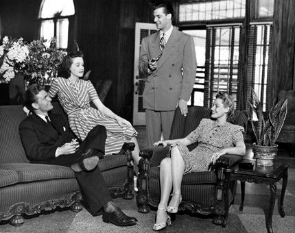
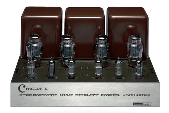
The solution that arrived in the late 1950s and early 1960s was to make relatively small, sealed loudspeaker enclosures that delivered deep bass, but were power hogs. This solution required powerful amplifiers, which the 1960s saw in tube power amplifiers such as the Harman Kardon Citation II, Dynaco MK-3, and Heathkit WM6 and the just developed solid-state power amplifiers.
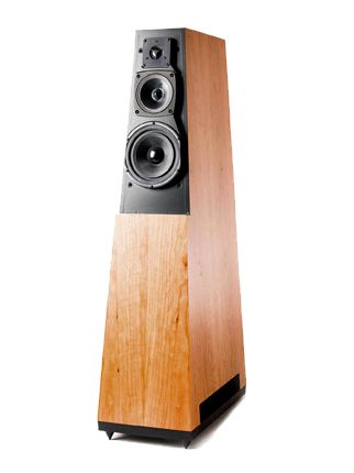
At the time, few imagined a return to 2A3-based single-ended amplifiers, nor could they image that in the next century 300W class-D power amplifiers would become mere commodities, costing less than a single KT88 output tube. Today, several high-end loudspeakers, such as the Vandersteen Quatro Wood, Model 5A, and Model Seven MKII, contain integral power amplifiers and subwoofers. In contrast to the usual approach wherein the addition of a subwoofer is something of an afterthought, the inclusion of an integral power amplifier and subwoofer makes the best use of subwoofer, as the loudspeaker designer knows what is needed to meld the subwoofer's output to rest of the passive loudspeaker, as its frequency response and phase characteristics are known variables.
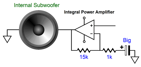
In addition, this powered bass setup overcomes the problem of creating deep bass within a relatively small enclosure by brute force. Moreover, an integral power amplifier can overcome a problem few realize exists; for example, floor-facing woofer sag. When a large woofer fires down, parallel with the floor, the heavy woofer cone sags due to gravity, which pulls the voicecoil slightly out of its center position in the magnet assembly. An integral power amplifier can present a small DC offset sufficient to undo gravity. In addition, the integral power amplifier must be powered from either a wallwart or by an internal power supply that attaches to the wall socket with a power cord. If the latter approach is used, then the third wire, the wire that attaches to the house ground, can be used to "ground" all the speaker driver frames to the house ground. Why? I have heard from many readers that this setup produces a more relaxed and effortless sound. In other words, a loudspeaker with a built-in active subwoofer might mate perfectly with a modestly powered tube amplifier, say only 25W in power output, yet deliver thunderous bass from the hidden 300W subwoofer amplifiers. As you can readily deduce, I like this approach, as it makes so much sense. Of course, some argue that the better approach is to go full integral power amplifiers for all the loudspeaker drivers. For example, a four-way loudspeaker would also hold four power amplifiers and active crossovers, eliminating the hassle and expensive of inductors and huge capacitors. If you don't mind solid-state amplification, why not? What if, instead, you are a tube-loving audiophile? Few loudspeaker makers are about to include four tube power amplifiers in each speaker enclosure. Even just one tube amplifier for the midrange and tweeter and one solid-state power amplifier for the woofer is asking too much—besides vacuum tubes are microphonic so shaking them directly is never a good idea. Thus, what sort of tube-friendly solution can we devise?
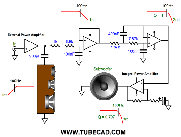
Including an integral solid-state power amplifier for the woofer (or subwoofer) is a great idea, as it would greatly unload the external tube power amplifier. Or would it? The way that loudspeakers with integral bass power amplifiers work is that the external power amplifier, either solid-state or tube, still delivers a full frequency response, while internal to the loudspeaker a passive crossover filter limits the deep bass from the higher-frequency drivers. In other words, the external power amplifier still has to deliver big deep-bass voltage swings, even though the load impedance rises at deep bass frequencies.
As you can see, the integral solid-state power amplifier uses the external power amplifier's output as its input signal. Now, the question to ask is: What if we used a high-pass filter before the external power amplifier? For example, say that we have a three-way loudspeaker with crossover frequencies of 500Hz and 5kHz and we place a 100Hz high-pass filter before the external power amplifier. Now, no passive crossover capacitor is needed for the mid-woofer, as we have pre-filtered away the deep bass. In addition, the external power amplifier no longer has to develop the big bass frequency voltage swings. So far, everything looks good, but what about the woofer and its internal solid-state power amplifier? How does the woofer amplifier get its input signal when we have filtered the low frequencies away? The solution is to put in place an inverse filter to restore the deep bass signal.
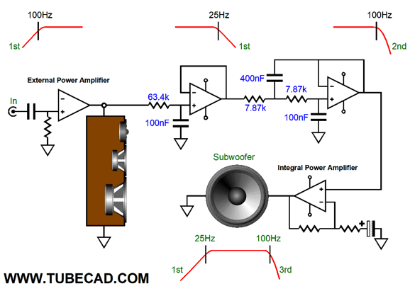
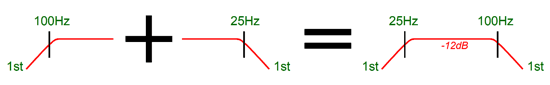
We place a low-pass, first-order filter at 25Hz on the signal coming from the external power amplifier. The result is that woofer amplifier sees a flat bandwidth of 25Hz to 100Hz.
The price we pay for this simple workaround is an insertion loss of -12dB; in other words, the bass signal is down relative to the external power amplifier's output by -12dB or 1/4 . So, do we set the integral solid-state power amplifier's gain to 4X to restore unity gain? We could, but the woofer is likely to be far less efficient than the midrange and tweeter. Why else bother with this elaborate setup, as we want our relatively weak tube-based amplifier to roar, which implies high-efficiency loudspeaker drivers, say 100dB types. Well, a 12in woofer in a sealed enclosure with with deep bass response will probably come in at about 88dB at one watt. In other words, to get the woofer to match the 100dB midrange and tweeter will require a boosted signal of +12dB or four times the voltage swing. Thus, we need to multiply the original gain of 4 by 4 to get 16 (+24dB).
How much power does the integral solid-state power amplifier have to put out? Let's assume that the external tube-based power amplifier puts out 25W, which implies 20Vpk into an 8-ohm load. We then multiply 20Vpk by 4 and get 80Vpk, which into an 8-ohm load equals 400W. This might seem outrageous, but 400W is not that big a deal for class-D power amplifiers. On the other hand, if two 88dB woofers are used in parallel, making a 4-ohm load, we gain +6dB due to the doubling of emitting surface, so only 40Vpk would be needed, and a 200W amplifier could be used. On the other hand, if a flea-power single-ended tube power amplifier was used that only put out 4W (8Vpk), the integral solid-state power amplifier would only need to deliver 32Vpk and 64W into an 8-ohm woofer or 16Vpk (32W) into two 8-ohm woofers in parallel.
Limited Low-Frequency Output Transformers The higher the frequency, the smaller the transformer can be; but the inverse also holds true, the lower the frequency, the bigger the transformer must be. Here is an example: a power transformer designed for 120Vac at 60Hz can only see 100Vac at 50Hz, as 120Vac against 50/60 equals 100Vac; conversely, a power transformer designed for 120Vac at 50Hz can see 144Vac at 60Hz. Returning to our output transformer, a transformer that can deliver 10Vac at 25Hz can deliver 40Vac at 100Hz, which implies much more power into the same load resistance. Once again, the higher the low-frequency cut off frequency, the smaller the output transformer can be. Airplanes use 400Hz power transformers, which compared to the same VA rated transformer designed for 60Hz use, are surprisingly tiny. Making a transformer especially optimized for higher-frequencies requires thinner laminations and thicker wire (less DC resistance), as we need far less inductance. In addition, since we have increased the low-frequency cutoff frequency, the core can be much smaller and higher in quality. In other words, a tube-based power amplifier with a 25W power bandwidth of 100Hz to 20kHz could sport an embarrassingly small output transformer.
Loudspeakers with Internal Active Woofer
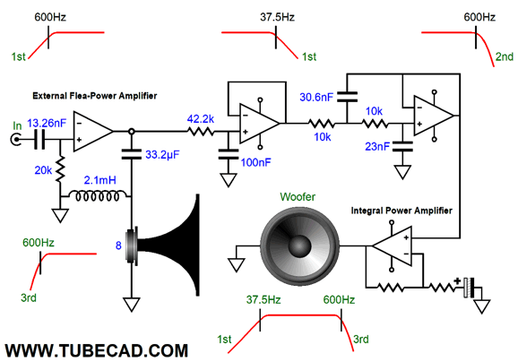
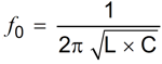
The horn driver sees a 2nd-order high-pass filter at 600Hz, with a Q of 1, which combined with the pre-filter Q of 0.707 results in a final Q of 0.707. By the way, the formula for a 2nd-order LC crossover's Q is Q = R√(C/L) where R is the driver impedance; C, the capacitor value in Farads; and L, the inductor value in Henries. So, lets check my math. Does 8√(0.0000332/0.0021 equal 1? Indeed, it does. The next formula is for finding the crossover frequency. I get a result of 603Hz, which is close enough. To find the value of L take R and divide by 2¶Fo and then multiply the result by 1000 to get the value in millihenries. For the capacitor value, take 159155 and divide by R and then divide again by Fo, which will give the answer in µF. Okay, what is the downside to the idea of pre-filtering the signal into the external power amplifier? The downside is hum. Most tube power amplifiers put out a good amount of hum, which our 600Hz high-pass filter will do nothing to eliminate, as the hum originates in the power amplifier. The integral solid-state power amplifier will treat this residual hum as audio signal and effectively boost it in its effort to restore flat bandwidth. Not good. In other words, the tube power amplifier must be well designed and built. For example, in this last design, with the 600Hz pre-filter, the hum from the flea-powered amplifier will be boosted by tenfold. I should mention that one huge danger of bi-ampping and any other direct coupling of power amplifier to midrange or tweeter is that weak connection with an interconnect and RCA jack can result in full output from the amplifier at 60Hz. Supremely not good, as far as the tweeter is concerned.
In contrast, doing a blend of active and passive crossovers, as I have done here, saves the day, as the delicate drivers will still be protected from the low-frequency onslaught. By the way, when dome tweeters blow, they often produce perfect circle smoke rings, dazzling but disheartening.
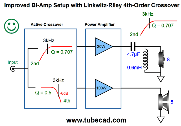
The 6.6µF capacitor's impedance at 60Hz is about 400 ohms, which prevents the tweeter from burning out due to a lost ground connection. The woofer does not need high-frequency protection, but it would benefit from the inclusion of a Zobel network to undo its series inductance. By the way, the tweeter amplifier only offers one fifth the power output. Why? Two reasons: we don't need a ton of power at high frequencies and the tweeter was 7dB louder in SPL, so its power need not be as powerful. (Imagine an OTL amplifier with a 6.6µF output coupling capacitor.) Even more protection for the delicate tweeter would be a 2nd-order passive filter combined with an active, Butterworth 2nd-order high-pass filter; the two combine to make a 4th-order Linkwitz-Riley crossover.
The woofer sees two cascaded Butterworth 2nd-order 3kHz low-pass active filters before its power amplifier. The woofer directly couples and enjoys the full damping factor the amplifier offers. Think about the advantages of not sending its audio signal through hundreds of feet of 18-gauge magnet wire (in the inductors).
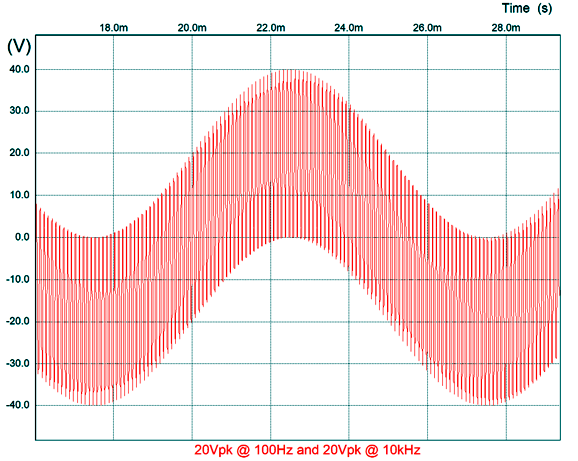
Full Strength: No Pre-Filtering Here is an example: imagine a power amplifier that must deliver two frequencies at once, 100Hz and 10kHz. Each frequency is 20Vpk, so the output needs to swing how much peak voltage? Many guess wrong and say 20Vpk. Alas, the amplifier needs to swing 40Vpk, as the two frequencies add together. Many imagine that the speaker cable is much like a three-lane freeway, with big slow trucks in one outside lane, mid-sized family sedans in the middle lane, while fast, small sport cars filter the other outside lane. But speaker cables are much more like single lane road with the sedan riding atop the truck and the sport car atop the sedan. At any given infinitely tiny slice of time, the amplifier's output voltage is at only one voltage, not three different voltages and certainly not three different frequencies traveling independent of each other.
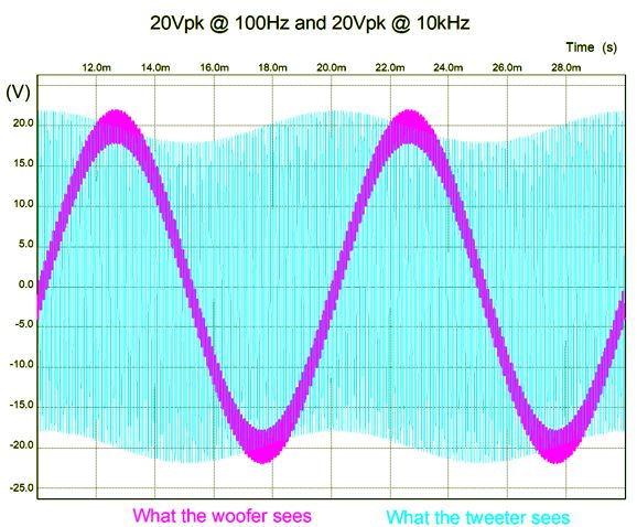
Now imagine a two-way loudspeaker with a 1kHz crossover frequency attaching to this amplifier. The 1kHz crossover frequency equally divides the audio bandwidth between the two frequencies, as 1,000Hz/100Hz = 10,000Hz/1,000Hz. Assuming first-order, -6dB-per-octave, crossover slopes, what is the peak voltage swing the woofer and tweeter will see in the face of these two 20Vpk frequencies? The answer is more than 20Vpk, as the first-order slope is so shallow; 22Vpk is what each driver will see. Why not 20Vpk? The first-order crossover slope is only -20dB per decade, so the woofer will see 2Vpk of 10kHz riding atop 20Vpk of 100Hz, while the tweeter will see 2Vpk of 100Hz atop 20Vpk of 10kHz.
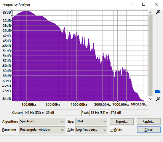
You can readily understand why third- and fourth-order crossovers were devised. If you have ever used the audio editing program Audacity to plot a frequency spectrum of a selection of music, you will see that that most the activity falls between 50Hz to about 600Hz, depending on the music and the instruments played, with electronic music breaking the pattern.
This bass-heavy frequency demand helps explain why a direct-coupled electrostatic power amplifier need only provide full-power bandwidth out to about 6kHz; it also explains why we have 12in woofers and 1in dome tweeters. Mind you, full-power bandwidth is not the same as the amplifier frequency response at lower output swings, which should be flat across the audio spectrum. Nonetheless, even a first-order high-pass filter at 100Hz greatly unloads a power amplifier, although not nearly as much a 500Hz crossover frequency would. (I sadly remember seeing my woofers swing back and forth as I played a severely warped LP, something that CDs never prompted.)
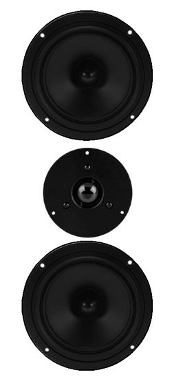
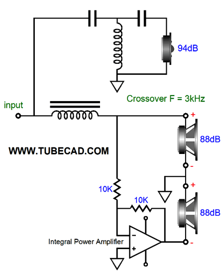
Okay, even if we do not limit the low-frequency response of the external power amplifier, we can still have fun with an integral power amplifier. In 2013's post 261, I show many possible power booster setups, wherein a flea-power amplifier's output is magnified by either a bigger power amplifier or by an impedance-multiplier circuit (IMC). Here is a simple example: a two-way speaker that uses a 94dB tweeter and two 88dB woofers in a D'Appolito arrangement, with the tweeter placed between the two woofers.
We do not want to place the two 8-ohm woofers in parallel, making a 4-ohm load. The workaround would be to use an internal power amplifier to drive one of the woofers, while the other is driven by the flea-power amplifier.
The bottom woofers sees the same signal that the top woofers, in spite of the phase reversal, as the internal amplifier's output goes to the negative speaker terminal. The two woofers still present an 8-ohm load, but the combined SPL is now -6dB higher, so they deliver 94dB, just like the tweeter. (Now, imagine that we remove the connection to ground between the two woofers. Why? It's not really needed and then it would seem as if the flea-power amplifier was actually driving both woofers.)
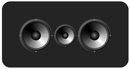
Possibly a more interesting design would be to use a 94dB fullrange crossover at 400 hz, with two 88dB woofers flanking, and with the same internal inverting amplifier treatment. This would be much like the old Quad ESL-57 electrostatic speaker that used the D'Appolito arrangement before D'Appolito.
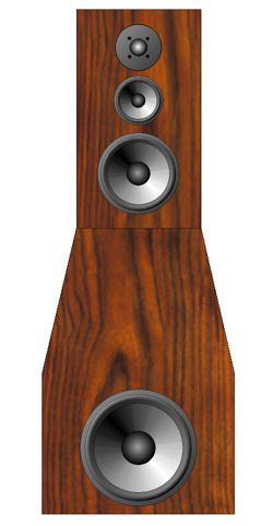
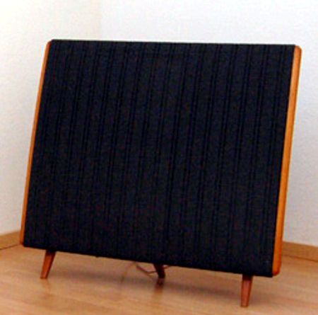
The Dahlquist DQ-10 loudspeaker was an attempt to make a speaker that looked like a Quad and sounded like a Quad, but using dynamic speaker drivers rather than electrostatic panels. Well, this three-driver arrangement could do both, as the fullrange could be used in a dipole setup, with the two woofers getting sealed boxes. (Be sure to see post 396.) One super simple semi-powered loudspeaker that I would love to hear would be a tall, narrow loudspeaker that held four full-range drivers, say 5in types. Only one of the drivers would be driven by the flea-power amplifier, while the remaining three drivers would be powered by an internal solid-state power amplifier. If we increase the radiating area of a loudspeaker by fourfold, we gain 12dB in SPL, which would bring an 88dB driver up to 100dB, allowing a single-ended 2A3-based power amplifier to roar. All four 5in drivers could face forward as line array—or we could place three in the back of the enclosure.
This would be something like a Bose 901, in that most of the sound output would be aimed at the back wall. In the 901, the reflected sound accounted for 89% of the output; in this speaker, 75%. I have never been convinced that Dr. Bose got the right ratio, believing that less reflected output would be closer to the mark. Well, in this setup, we could place a simple volume potentiometer on the back of each loudspeaker cabinet that would allow us to adjust the direct-to-reflected ratio. (My guess is that each music genre would have its preferred ratio.) Indeed, a remote-controlled volume would be the best approach. Note that in this setup, the integral power amplifier gets its input signal from the external tube-based power amplifier, so the tube sound should still prove evident. That fact that the sound that first hits our ears comes from the front fullrange that is entirely tube driven, makes me less worried than I might otherwise be. The interesting question is how should the three drivers be driven? In series or in parallel?
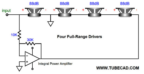
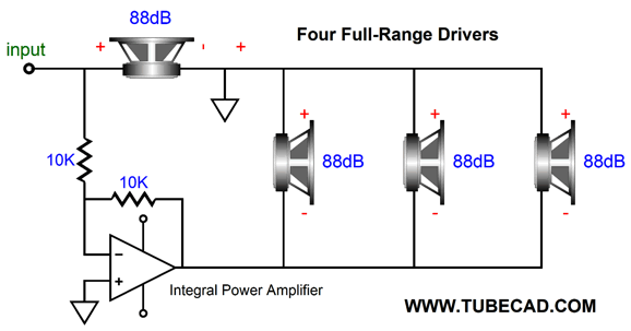
Here we see the three fullrange drivers in series, making a 24-ohm load. This will require big voltage swings form the integral power amplifier, but relatively low current swings. Do not make the mistake of thinking that the tree drivers in series will suffer from decreased damping; they won't. The Qes remains the same, as Re resistance must be multiplied by three, but then this product must be dived by three due to three-fold increase in Bl. In other words, a giant step sideways. The other approach is to create a 2.67-ohm load by placing the three in parallel.
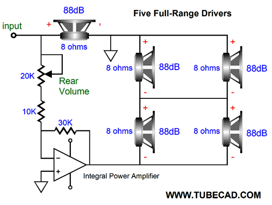
Now the internal power amplifier runs in unity gain and must deliver relatively high current swings. Fortunately, many power amplifier modules are made just for low-impedance loads, which is what subwoofers and car stereo systems require. If the tube-based amplifier put out 25W, 20Vpk, the internal amplifier would deliver the same 20Vpk to the 2.67-ohm load, resulting in 75W of power delivery. A 48Vdc @10A switcher power supply could easily drive the internal amplifier. Note that the ground connection between the single fullrange and the remaining parallel three fullranges is essential in the above schematic; but it is not essential in the previous version with all four drivers in series. We could increase the rear-firing fullrange count to four.
Now the integral power amplifier sees an 8-ohm load. The math gets slightly more difficult here, as the four rear driver only see 50% of the output voltage from the internal amplifier, so we lose -6dB in SPL, but we gain +12dB from the fourfold increase in emitting area, leaving a net gain of +6dB. With the volume control set at full output, the internal amplifier's gain will be 3 (+9.5dB), which added the increase SPL of 6dB yields 15.5dB more SPL from the rear speaker drivers than the front driver. With the volume control set at the lowest output, the internal amplifier's gain will be unity (0dB) and the rear driver will put out +6dB more SPL. Imagine that your audiophile buddies come over to your place and see two of these loudspeakers. If they do not see the backs, they will assume that only two 5in drivers are employed. They do not expect much, as your 2.5W flea-power amplifier looks ill suited to the task. You fire up some Mahler symphony, say his 3rd. Your friends' mouths fall open as the room fills with a huge sonic presentation. (By the way, I would cheat a bit and give the front fullrange its own tweeter, with an extremely high-frequency crossover of 8kHz. I would pick the actual frequency based on the fullrange's own series inductance, so that the single fullrange and tweeter would establish a relatively flat impedance plot.)
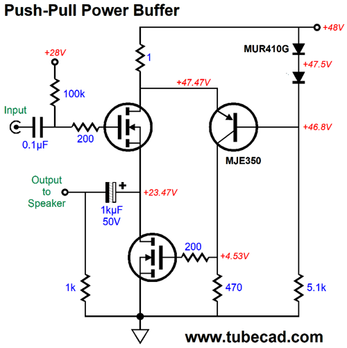
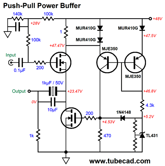
Amazing Push-Pull Power Buffer
This version uses a mono-polar power supply, but is not required to do so, as a bipolar power supply could just as easily be used with slight modifications. The top MOSFET sees the input signal at its gate, while the PNP transistor strives to see a fixed voltage at its emitter. If the top MOSFET draws more current, the 1-ohm drain resistor sees a larger voltage drop, which works to reduce the PNP transistor's current conduction, which in turn causes the voltage drop across the 470-ohm collector resistor to fall, forcing the bottom MOSFET to conduct less current. The result is that the top MOSFET draws a nearly constant-current flow, while the bottom MOSFET varies it current conduction to keep the top MOSFET' current flow constant. In other words, the bottom MOSFET is working into a near constant-current source. Thus, no real push-pull operation obtains as long as output current into the external load impedance does not exceed the idle current. Once this threshold is passed, the push-pull operation kicks in.
Interestingly enough, the top MOSFET never shuts off altogether, but the bottom MOSFET does. Note how the blue current plotline never hits 0A, while the green plotline does. I decided to add some bells and whistles in the form of a DC current mirror and two extra rectifiers to limit the voltage drop across the 1-ohm current-sense resistor and an upgrade in the output coupling capacitor, going from a polarized electrolytic to a non-polarized electrolytic with a film bypass capacitor.
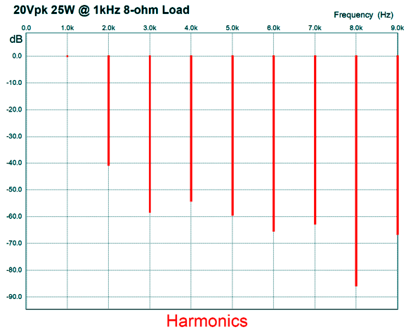
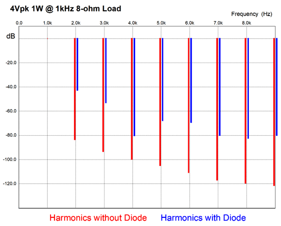
What tickled me about this power buffer, asides from its simplicity was its distortion harmonic structure.
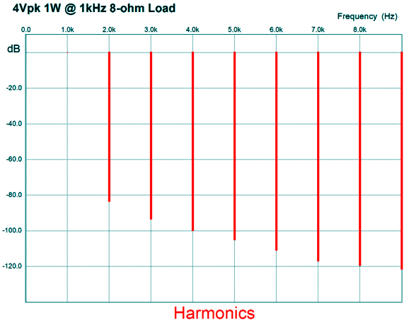
Note the approach to the astoundingly rare harmonic structure, wherein the odd harmonics are substantially further down than the even harmonics. This is the elusive sonic fingerprint that I have mentioned here before. Only a handful of circuits have achieved it, but I conclude that this is what we sought along, but knowing exactly what was making music playback delicious to our ears. Well, this buffer's harmonic structure hints at it, as the 3rd harmonic is greatly reduced. Note that the THD is about 1%, which isn't that bad considering the 25W of output and the circuits simplicity. At 1w of output, the THD is far below 0.1%. (In my SPICE simulations, I used the IRF230 MOSFET model.)
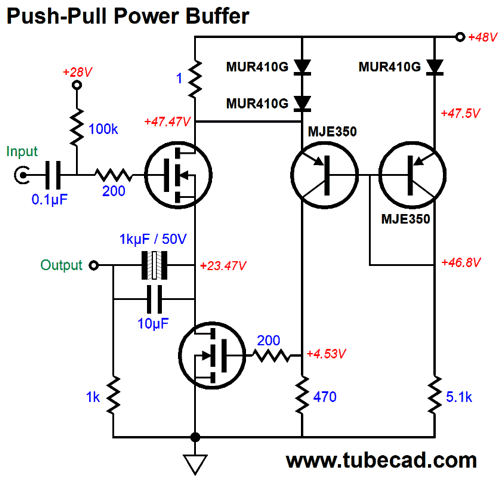
An amazingly single-ended harmonic signature from a push-pull output stage. Well, since I can never leave any topology alone for long, I wondered if I couldn't force the bottom MOSFET to never cutoff. The first step is to figure out why it shuts off under normal operation. The answer is that once the top MOSFET breaks out of its constant-current state of conduction, the voltage drop across the 1-ohm current-sense resistor exceeds the PNP transistor's emitter turn-off voltage, causing the voltage drop across the 470-ohm to drop to 0V. Thus, to prevent the bottom MOSFET from shutting off completely all we have to do is impose a low-voltage limit on the 470-ohm resistor. The following variation show how easily this can be accomplished.
At idle and within the class-A window of operation, the 1N4148 signal diode remains effectively out of the circuit, as it is not forward biased and conducts no current. Once the left PNP transistor ceases to conduct, the diode becomes forward biased and the diode applies the breaks on any further downward voltage swing on the 470-ohm resistor, resulting the bottom MOSFET seeing enough gate voltage to still conduct. Let me be super emphatic here: this in no way constitutes class-A operation on the cheap. True, honest-to-God, class-A, push-pull operation requires more than the opposing output devices never cutting of their current conduction; it requires that both meaningfully conduct, offering an opposing resistance, not a near infinite impedance. Of course, marketing departments would disagree, having found a loophole in the fine print, a marketing bonanza for the taking. Okay, if this isn't a form of cheap class-A, why bother with keeping both output devices from ever cutting off? MOSFETs are wonderful, being easy to drive and robust, but they do suffer from non-constant input capacitance. The capacitance between the MOSFET's gate and drain is influenced by both the gate and the drain voltages, being highest when both are zero. If the MOSFETs never completely turn off, re-engaging them should be easier and glitch-free. Well, that was the idea behind the effort. Okay, how well does this variation work? Mixed results. Within the class-A window of operation, distortion goes up, not down.
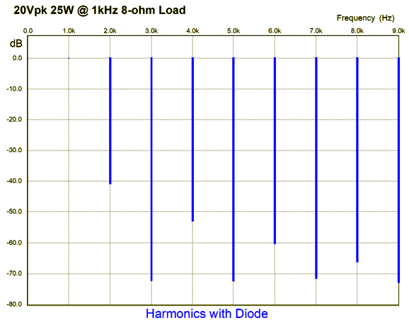
At the other extreme, in other words, at full output, the astoundingly rare harmonic structure astounds even more.
Note that the 3rd, 5th, 7th, and 9th harmonics are crazy down relative to the even harmonics. The THD does change much from 1W of output; in fact, it might have gone down slightly. How many times have we heard a power grow coarse and congested as the volume goes up? Well, perhaps this power buffer will sound just the opposite, growing ever sweeter with increased volume. So which is preferable? The only way to find out is to build both versions and hold a shootout. One idea that comes to mind is to build a scaled down version that runs off either a 12Vdc or 15Vdc power supply and uses lateral N-channel MOSFETs. Why? Who would want a 1W power buffer? Audiophiles who own horn speakers or low-impedance headphones would. Two BUZ901 MOSFETs would be a fun start. How do we drive this buffer? I would either build an especially hot line-stage amplifier that could easily swing 20Vpk of output voltage or I would use an Aikido gain stage with a 12AY7 input tube.
Music Recommendation: More Joep Beving
Apparently, Beving is a big fan of Alfred North Whitehead. How cool is that? As a happy coincidence, I am presently rereading Whitehead's short book, The Aims of Education, and loving every page of it. Whitehead was far more out there than you might ever expect. Yes, he co-wrote the Principia Mathematica with Bertrand Russell, whose was Whitehead's former student. Whitehead was not just a mathematician, but also a philosopher who did metaphysics. In fact, he had a theory of gravity in opposition to Einstein's. In short, Whitehead is due for a huge revival, which he is beginning to have in ecology and theology, amazingly enough—or, perhaps, not so amazing, as Whitehead was a staunchly opposed to materialism, which he described as, "a scheme of scientific thought framed by mathematicians for mathematicians." His alternative view was to stress organism and events and process. "Henosis" is the ancient Greek word for mystical unity and it is also the title of Beving's latest album. I have only listened to it once so far, so I not come close to fully "digesting" it yet. Soon. Do the same.
//JRB
User Guides for GlassWare Software
For those of you who still have old computers running Windows XP (32-bit) or any other Windows 32-bit OS, I have setup the download availability of my old old standards: Tube CAD, SE Amp CAD, and Audio Gadgets. The downloads are at the GlassWare-Yahoo store and the price is only $9.95 for each program. http://glass-ware.stores.yahoo.net/adsoffromgla.html So many have asked that I had to do it. WARNING: THESE THREE PROGRAMS WILL NOT RUN UNDER VISTA 64-Bit or WINDOWS 7 & 8 or any other 64-bit OS. I do plan on remaking all of these programs into 64-bit versions, but it will be a huge ordeal, as programming requires vast chunks of noise-free time, something very rare with children running about. Ideally, I would love to come out with versions that run on iPads and Android-OS tablets.
//JRB
|
|
John Gives
Special Thanks to the Special 82
I am truly stunned and appreciative of their support. In addition I want to thank the following patrons:
All of your support makes a big difference. I would love to arrive at the point where creating my posts was my top priority of the day, not something that I have to steal time from other obligations to do. The more support I get, the higher up these posts move up in deserving attention. Only those who have produced a technical white paper or written an article on electronics know just how much time and effort is required to produce one of my posts, as novel circuits must be created, SPICE simulations must be run, schematics must be drawn, and thousands of words must be written. If you have been reading my posts, you know that my lifetime goal is reaching post 1,000. I have 539 more to go. My second goal is to gather 1,000 patrons. I have 918 patrons to go. Help me get there.
Only $12.95 TCJ My-Stock DB
Version 2 Improvements *User definable Download for www.glass-ware.com |
||


| www.tubecad.com Copyright © 1999-2019 GlassWare All Rights Reserved |