| John Broskie's Guide to Tube Circuit Analysis & Design |
16 April 2019 Post 462
New Adventures in the White Cathode Follower
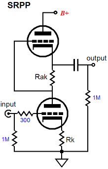
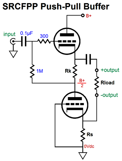
Its brothers are the SRPP and SRCFPP. The latter is my invention and "SRCFPP" is an acronym for "Series Reflexive Cathode Follower Push Pull" (Actually, to be extra precise, SRCFPP is an initialism, as each letter must be voiced separately, much like CIA and IRS.)
All three circuits work in a similar way, as all three—in order to produce push-pull operation—use a current-sense resistor (Rs) to create an anti-phase signal to the drive the enslaved triode. The White cathode follower places Rs at the top; the SRPP, in the middle; and the SRCFPP, at the bottom. All three circuits must be run in strict class-A and all are load dependant, which means that each must be optimized for a single intended external load impedance. One size does not fit all.
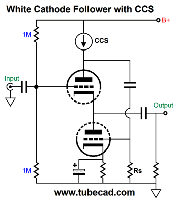
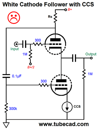
Let's pull back and imagine some extremes with the White cathode follower. Let's start with our replacing the current-sense resistor with a constant-current source.
The constant-current source shields the rest of the circuit from the B+ voltage ripple, which is good; it also develops huge signal gain to drive the bottom triode, with the result of a greatly lower output impedance. All positives. The problem, however, is that the buffer no longer operates in push-pull, having been transformed into a single-ended circuit, which means that the maximum current swing into the external load impedance is equal to the White cathode follower's idle current, not the twice the idle current that a true White cathode follower can deliver in push-pull. The top triode now runs in constant-current and the bottom triode sees all the current variation required to drive the load impedance. Okay, let's now imagine that the replace the bottom triode's cathode resistor with an un-bypassed constant-current source.
Once again, we have eliminated push-pull operation and created a busy cathode follower that needlessly holds current-sense resistor and coupling capacitor to the bottom triode's grid, as only the top triode sees any current variation in the presence of input signal. The ideal White cathode follower configuration is optimized to drive one external load impedance, which ensures equal—but out of phase—current swings from top and bottom triodes. If the White cathode follower doesn't push and pull it really isn't a White cathode follower. This brings to mind a recent email from the Valve Wizard himself, Merlin Blencowe. He pointed out that this circuit from post 460 was, in fact, a White cathode follower.
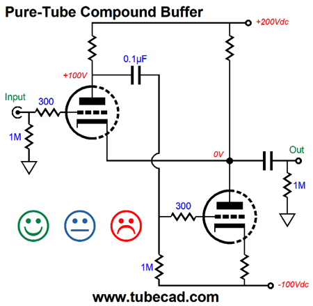
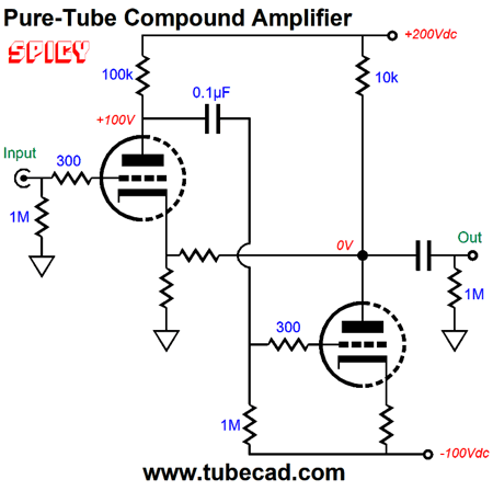
I couldn't argue with Merlin, as that was what I had called the circuit before; for example, in my own Tube CAD program. Now, if both triodes are the same type and draw the same amount of current, then this circuit is definitely a White cathode follower. But what if the triodes differ, say a 12AX7 at the top and a 6CC33 at the bottom? What if the top triode draws 1mA, while the bottom triode draws 300mA? If nothing else, we know that the old formula for finding the optimal current-sense resistor value, Rs = (rp + 2Rload)/mu, no longer works, as these two triodes will never achieve balanced push-pull operation. In addition, a true White cathode follower will never deliver any gain, but we can easily get gain from the pure-tube compound circuit.
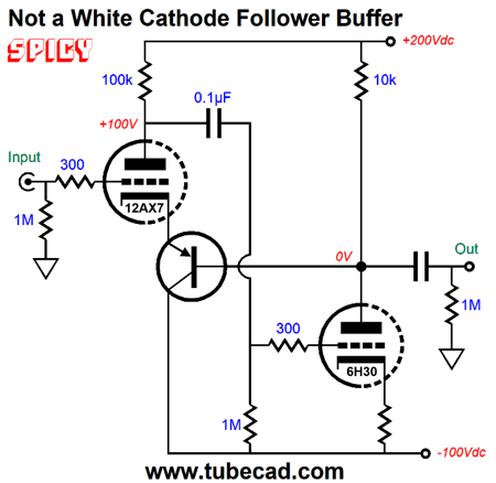
This circuit is an amplifier, not a buffer. Now, what if we break the current path from the top triode's cathode to the external load, do we still have a White cathode follower?
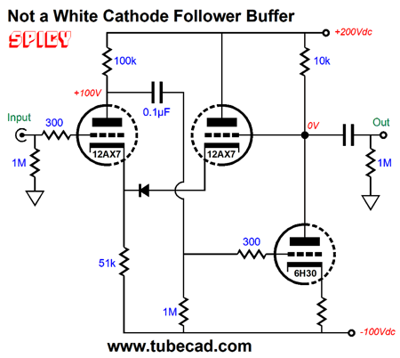
The 6H30 draws 20mA of current, while the 12AX7 draws 1mA and none of the 12AX7's current flows into the load impedance. (Well, some current does flow through the PNP transistor's base; so, let's imagine that a P-channel MOSFET were used instead of the PNP transistor.) In fact, we do not have to resort to solid-state devices to break the current path, as the following all-tube circuit does so as well.
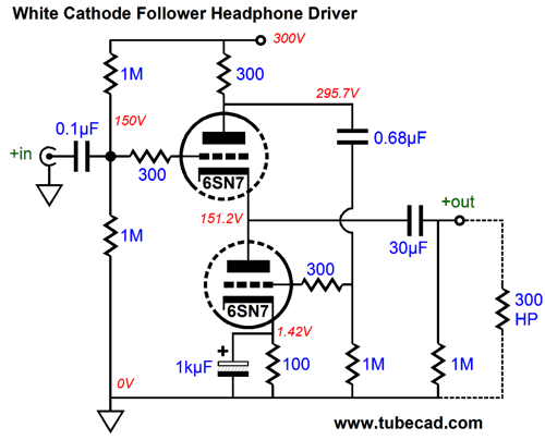
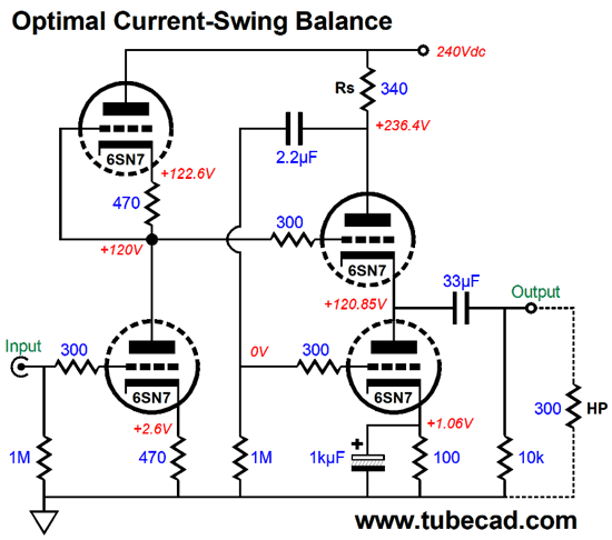
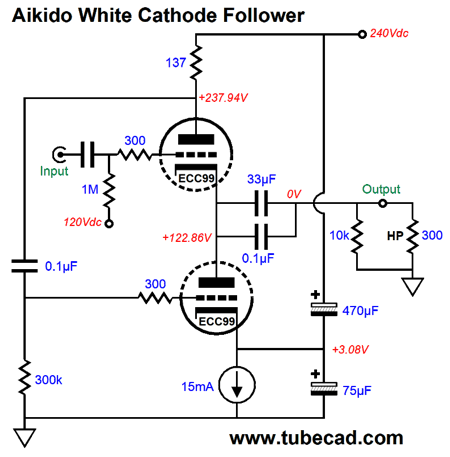
The diode introduces a fixed voltage drop, so the dissimilar plate voltages between the two 12AX7 triodes can be overcome; this diode can be removed with no AC change to the circuit. The "SPICY" label denotes that while you can get these circuits to work well in SPICE simulations, reality will certainly prove more recalcitrant. What all three circuits lack is a DC feedback loop to keep the output centered at ground potential (0V). My view is that once we stray too far from the White cathode follower formula, Rs = (rp + 2Rload)/mu we should stop thinking of the circuit as a White cathode follower. We do have some latitude, however, as we can sacrifice some of the potential balanced current swings for improved PSRR. Here is an example circuit that has been optimized for balanced output current swings into the 300-ohm load.
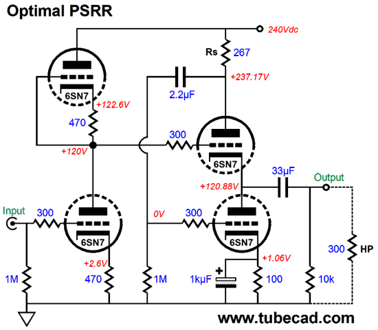
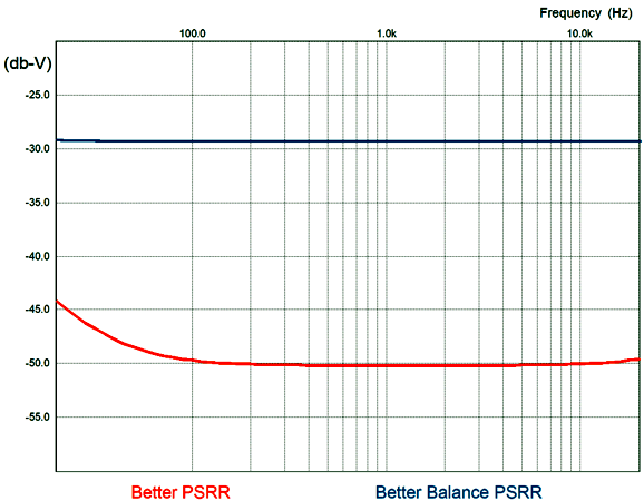
The input stage is NOT an SRPP, but a grounded-cathode amplifier with an active plate load. This input stage also defines a two-resistor voltage divider that delivers 50% of the power-supply noise to the White cathode follower's input. So, does the 300-ohm headphone see 50% of the B+ voltage ripple, i.e. a PSRR of -6dB? No. The White cathode follower by itself delivers a PSRR of -11dB (29% of the ripple leaks out), but the ripple is inverted relative to what appears at the B+ voltage. When we cascade the input stage and White cathode follower we get a PSRR of -29dB, a great improvement. And, if we further tweak the current-sense resistor value for optimal PSRR, we get a 20dB improvement in PSRR (-49dB).
All that has changed is the current-sense resistor value, which yields an improved PSRR figure and slightly less gain and slightly more distortion.
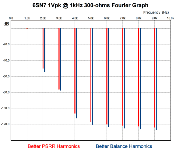
The optimized for PSRR version presents only a tad bit more distortion, but its PSRR is hugely improved.
Okay, which is better? It depends. If you are using a well-regulated power supply, then the version optimized for current balanced is certainly better. On the other hand, if the B+ voltage is more typical of tube gear, containing many millivolts of ripple, then the optimized for PSRR version is better. By the way, the very notion of optimal part value is seemingly strange to many. Here is an example, about 20 years ago, I received an email asking for my help with a simple grounded-cathode amplifier circuit that failed to deliver the promised sonic gold. As I surveyed the supplied schematic, I queried the use of a 1.8 Meg cathode resistor, as a value closer to 200 ohms would have been optimal. I was told that he only owned some high-praised resistor brand in that value, so he used it, knowing that part brand was far more important than part value. And people wonder why I drink.
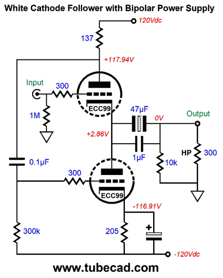
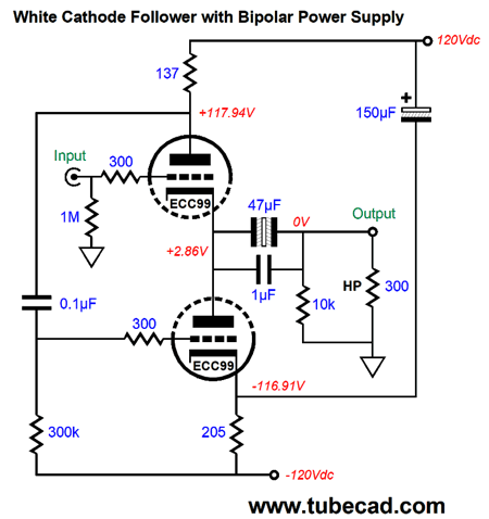
White Cathode Follower and Bipolar Power Supplies
Note that the cathode resistor is bypassed. If we prefer to leave it unbypassed, we must add a cathode resistor to the top triode.
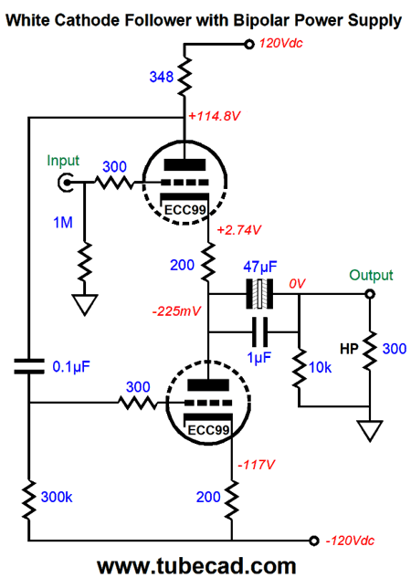
Note that the current-sense resistor (Rs) is now much larger in value, as the cathode resistors reduce the triode's transconductance. In general, I prefer this setup with two unbypassed cathode resistors, as they further linearize the triodes, but they also increase the output impedance, which will diminish the damping factor, which in turn can make for a fatter bass response. One workaround is to use fixed bias on the bottom triode.
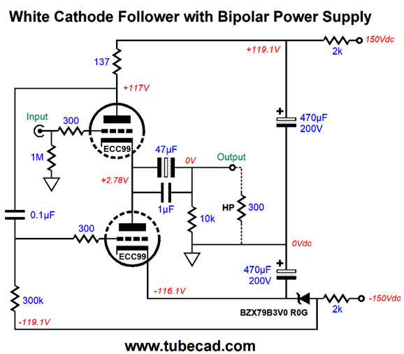
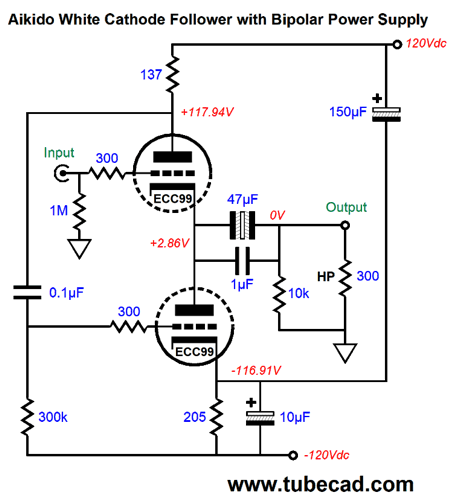
The zener provides the needed voltage drop and offers a low impedance. The bipolar power supply voltages are no longer symmetrical, but that is okay, as the two triodes still see roughly the same cathode-to-plate voltage differential. Of course, the zener can be replaced by a resistor, but the zener offers a tighter fixed bias. Note how the zener is effectively bypassed by the 470µF capacitor to ground. This raises an interesting question: What would happen if we terminated this capacitor into the positive rail voltage rather than ground?
Looks rather ultra-path does it not? One result is that we saved the cost of using two capacitors. More importantly, the PSRR improves, going from -29dB to -45dB . If we examine the leaked power-supply noise at the output we see that the output ripple is in phase with the positive rail, but out of phase with the negative rail. This means that we can achieve a power-supply noise null at the output by using two bypass capacitors, one that terminates into the positive rail and one that terminates into the negative rail.
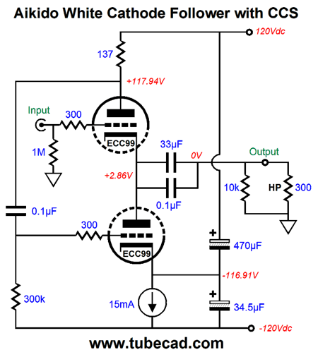
Using the ECC99 with these bipolar power-supply rail voltages and this idle current and these capacitor values created the deepest power-supply noise null in SPICE simulations. Actual mileage may vary. To understand what is going on note that the bottom triode sees a large portion of the positive-rail ripple via the 0.1µF capacitor. By feeding the bottom triode's cathode the optimal amount of ripple and in the correct phase, the triodes see a matched current variation due to the ripple that results in a ripple null at the output. I noted that the bottom triode's cathode-to-plate voltage was 3V, which is enough to let us use a constant-current source in place of the cathode resistor.
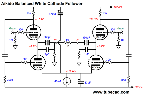
Note that the bypass capacitor ratio has changed, as the constant-current source offers near infinite impedance, which unlike the cathode resistor does not drag down the bottom bypass capacitor. By the way, the top bypass capacitor must be rated for at least 250V in this example, while the bottom capacitor can be a 6.3V type. Before leaving the bipolar-power-supply White cathode follower variations, let's look at a balanced version.
We still get to use non-polarized electrolytic coupling capacitors and the same two bypass capacitors and constant-current source, but at twice the set current flow. What did change was the external load impedance and, as a consequence, the current-sense resistor values. Okay, returning to the world of mono-polar power supplies and White cathode followers, can the same two bypass capacitor technique work to enhance the PSRR? Indeed.
The bottom bypass capacitor value is about twice that of the previous example, which makes sense if you think deeply about it. Note that the load impedance is back to 300 ohms and that the current-sense resistor value is back to 137-ohms. Is everyone mentally warm now? Great. Now we are going to see something altogether new.
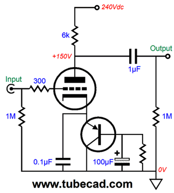
One huge problem with using capacitors to set fixed AC signal ratios is loose capacitor tolerances, especially with electrolytic capacitors, which requires our using a capacitance meter to carefully hand pick capacitors. Even with the capacitance meter, there is no real guarantee that the measured capacitance will persist with temperature changes and time. This is why using 1% resistors instead of 20% capacitors makes so much more sense. In this circuit, the 6.34k and 39k two-resistor voltage divider delivers the required ripple ratio to the PNP transistor base, which in turn delivers this critical amount of ripple to the bottom triode's cathode, resulting in the desired power-supply noise null at the output. For 90% of tube-loving solder slingers, this circuit will make no sense, as nothing establishes the 2.26V base-to-ground voltage, as the top resistor terminates into a large-value capacitor, not the B+ voltage. The answer is found in how transistors work. The transistor's base draws current, albeit a small amount. In this example, the 2N4403 draws enough current through its base to develop 2.26V across the 39k resistance. This small transistor offers a relatively high current gain (beta), so we can get away with the high-valued resistors. A transistor with only one third the current gain would require a bottom resistor value of 13k and top resistor value close to 2.1k ohms.
Auto-Bias with a Capacitance-Multiplier Circuit
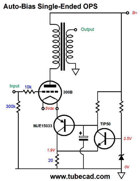
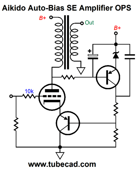
The PNP transistor functions as a capacitance-multiplier circuit, so the 100µF capacitor is effectively far greater in value. We can even use this technique to cathode-bias a large output tube, such as a 300B.
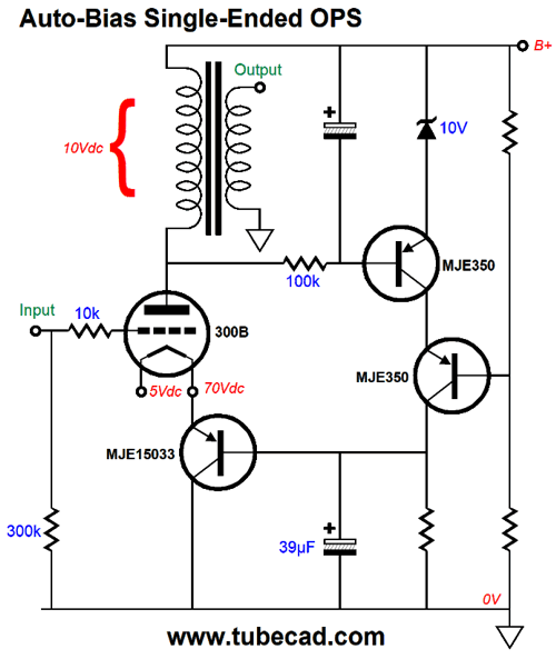
The NPN TIP50 high-voltage transistor monitors the voltage drop across the 20-ohm current-sense resistor. If the voltage drop is too low, the TIP50 will increase its current conduction and the PNP MJE15033 transistor's base and emitter voltage will fall as a result, causing the 300B to draw more current, as its grid will effectively become more positive relative to its cathode. Conversely, if the 300B is drawing too much current, the voltage drop across the 20-ohm resistor will be too high, causing the NPN TIP50 to conduct less, which in turn will force the 300B's cathode voltage higher, thereby reducing its current flow. In other words, auto-bias. In actual use, we need a few more parts, as shown below.
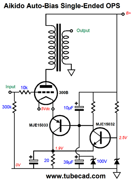
I know it looks vastly more complicated, but I only added two capacitors and one zener diode. The zener was added to limit maximum voltage the PNP MJE15033's base ever sees to 100V, which in turn will limit the maximum voltage across the NPN MJE15032. The capacitor shunting the 20-ohm current-sense resistor is needed to shunt away AC signal, so the NPN transistor only has to respond to shifts in DC voltage. The 10µF, in contrast, is a subtlety that only I would add. This capacitor introduces 1/3.9 of the power-supply noise to the PNP transistor's base, which then relays the portion of ripple to the 300B's cathode, resulting in an enhanced PSRR, as the ripple becomes nearly invisible to the 300B. In other words, as the ripple swing positively, the 300B's cathode swings negatively by 1/3.9 as much, which maintains a constant current flow in spite of the ripple. We could use the DCR of the output transformer's primary as current-sense resistance instead.
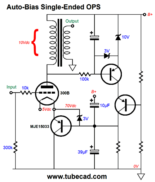
See post 426 for more details on the circuit shown above. Here is a variation.
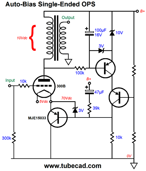
The two PNP transistors are in cascode to extend their voltage limit. The RC filter erases the AC signal that feeds the top PNP transistor its DC signal. The zener establishes the circuit's voltage reference. (We could bypass the zener with a large-valued capacitor.) If the 300B draws too much current at idle, the voltage drop across the transformer primary will exceed the zener voltage added to the transistor's base-to-emitter voltage, causing the topmost PNP transistor to increase its current flow, which in turn will increase the voltage drop across the collector resistor, causing the 300B's cathode voltage to rise, reducing the 300B's current flow. The only thing missing is the Aikido-mojo capacitors.
The 3V zeners were added to protect the PNP transistors at turn-off, as they limit the maximum base-to-emitter voltage to 3V in one direction and 0.7V in the other. In general, it always pays to be paranoid when dealing with high voltages and solid-state devices. Of course, larger valued capacitors can be used, as long as they abide by the same 1:mu ratio. Alternatively, we could use only one large-valued capacitor and add a resistor to realize the Aikido-mojo PSRR enhancement.
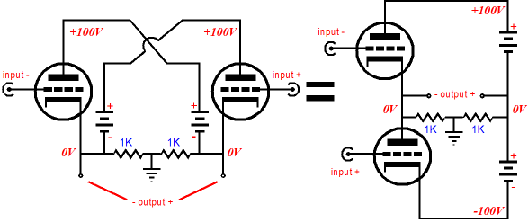
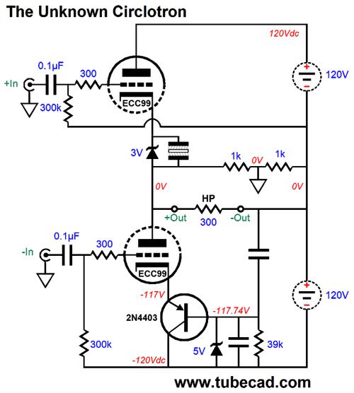
Now it's time to stretch our minds. I pointed out long ago in Cars, Planes, and Circlotron that an alternative Circlotron topology existed that would behave identically with the conventional topology, including the ability to be run in class-AB and to receive a balanced input signal of equal magnitude.
Alas, few know that this variation exists; fewer understand that it functions identically with the conventional circlotron.
One advantage it offers that it can use a single bipolar power supply per channel, rather than the two separate power supplies that the conventional circlotron uses.
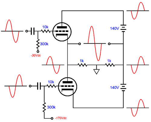
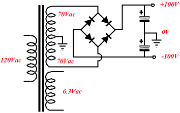
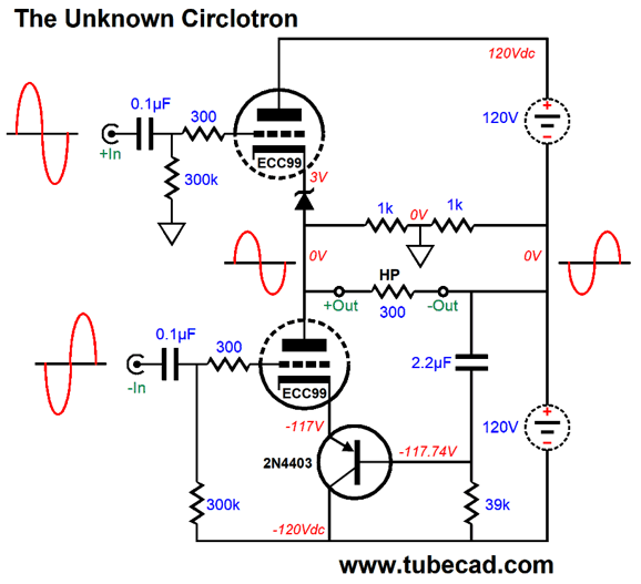
This means that each can be powered from a single center-tap primary. The disadvantage with this variation is that the bipolar power supply must be well filtered, as the ripple on the negative power-supply rail will mix with the input signal that the bottom triode sees. Well, we can use the capacitance-multiplier circuit to sidestep this problem.
Note that both output triodes see equal magnitudes of input signal, differing only in phase. Note that the ground falls mid-load, just as it does in a regular circlotron and that the output is balanced and not ground terminated. As for the problem of power-supply noise leaking in through the bottom triode, the PNP transistor's base is AC "grounded" through the capacitor that bridges its base and the inverting output, which is ripple-free. Well, mostly ripple free, as the top triode now introduces some leaked ripple, as its plate see the positive power-supply rail noise, but the bottom triode does not see the inverse. The workaround is to add an Aikido-mojo capacitor.
Okay, I did add more than one extra capacitor. The 5V zener is there protect the PNP transistor and the non-polarized electrolytic bypassing the top triode's zener is there to reduce zener noise and maintain a fixed cathode bias voltage, even when the top triode shuts off in class-AB operation. The top triode's grid resistor no longer terminates into ground, but into the inverting output. Why? This a garter-belt technique that helps prevent DC offsets. For example, if the bottom triode draws too much current, the non-inverting output will go negative and the inverting output will go positive, which will cause the top triode to see a more positive grid voltage and force a greater current conduction, which will work to restore balance and no DC offset. Of course, the safest route is to use a coupling capacitor.
Since we gained the output coupling capacitor, we can lose the input coupling capacitor.
More Loudspeaker Material
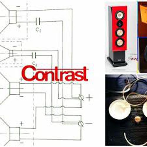
The company was Contrast Audio. I went searching and the following image was the only related thing I could find that explained what they were up to.
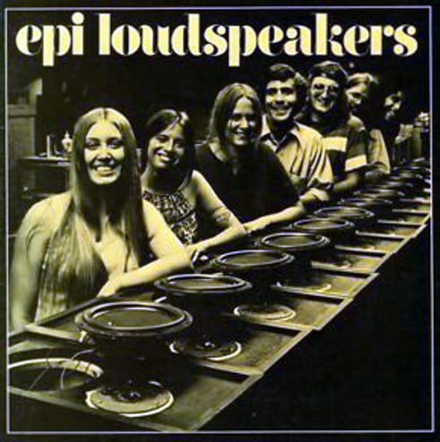
Apparently, they have reinvented the wheel. Long ago, as in half a century ago, an American loudspeaker company, EPI (aka, Epicure) did the same thing.
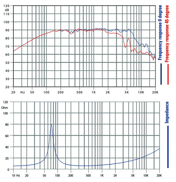
They, too, used no inductors, relying on their specially made woofers to smoothly roll off with a 2nd-order slope at about 3kHz; the tweeter did see at least one crossover capacitor. I liked the sound from the EPI speakers a great deal and I was not alone. Simply put, passive crossovers suck. Not putting a hundred feet of 22-gauge magnet wire in series with the woofer can only help. In fact, at the time I was buddies with an employee of Pacific Stereo in San Jose, California. He worked in the repair department and let me order any part that they had access to; thus, I got parts that were otherwise unattainable, such as turntable bearings, matched transistors, and speaker drivers. At age 20, I built my first belt-drive turntable with some of the parts he was able to provide, along with my own woodworking and visiting a glass-fabrication firm for my glass platter. Well, I bought many EPI replacement woofers over the years, as they worked well without a crossover; sadly, the foam surrounds fell apart with time. In short, this minimalist crossover approach is a great idea, if you can pull it off. Here is the impedance and frequency plots for a 5in woofer (5FE120) from the Italian company Faital Pro.
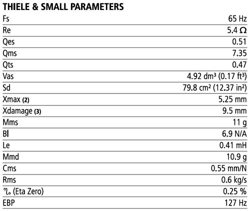
Note how the impedance rises after about 400Hz, which is due to series inductance (Le) of the voicecoil inside the magnet structure. Here are the Thiele-Small specs.
The inductance is specified as being 0.41mH, which implies a low-pass, 1st-order cutoff frequency of 3,100Hz with an 8-ohm resistance. The frequency plot seems to belie this calculation, as the output goes on to about 5kHz before falling off. What is happening is that at the higher frequencies, the driver begins to beam, which explains why the output at 45 degrees off axis (red plotline) falls off at something closer to 3kHz. One workaround seldom used is to place a 2-inch to 3-inch round piece of thick felt on the backside of the grill cloth right in front of the woofer. The felt usually sticks to the cloth, much like velcro, so you can experiment easily with no permanent damage to the speaker. They sell the thick felt at hardware and industrial-supply stores to place under the feet of big powered saws, drills, and anything else that vibrates. The felt acts as an acoustic low-pass filter. I have used this trick to tame hot, beaming tweeters, employing a disk of felt about 0.5 inches in diameter. Mind you, it takes about half an hour to get used to a tamed tweeter, as your ears will complain of not hearing enough sizzle. But once something closer to neutral is accepted by your ears, pull the felt disks off and be prepared to be stunned by how fake screechy the naked dome tweeter sound becomes. If you like the sound better with a felt disk, simply sew one loop of thread through the grill cloth and felt disk. Okay, returning to a minimal crossover, this 5in woofer would probably mate well with a tweeter that crosses over at 4kHz with a 2nd-order, high pass filter of a Linkwitz-Riley alignment, as the tweeter's output would be -6dB at the crossover frequency. Note that with the addition of the tweeter, the entire speaker would display a far flatter impedance plot. The alternative is to bi-amp, which would also eliminate the inductors in series with the woofer. Over 30 years ago, I built a tri-amp speaker system, using three identical 20W solid-state amplifiers of my own design. At the time, I also owned a 200W power amplifier that I used only to drive my electret headphone step-up transformer. Well, the three 20W amplifiers sounded far more powerful than the 200W beast. How is that possible? The tweeter amplifier never clipped. In addition, the tweeter was about 6dB more efficient than the midrange and woofer, so the 20W amplifier was effectively an 80W amplifier in terms of SPL. While experimenting, the first thing I noticed was the amazing increase in bass and lower midrange articulation that sounded closer to an electrostatic panel than an Audax 6in woofer.
Music Recommendation: Tidal Gold
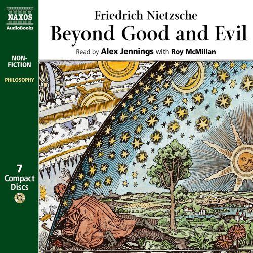
Tidal being Tidal, there might be, indeed probably, even more. For example, Tidal list 13 Friedrich Nietzsche albums under his name, but if you search for "Alex Jennings" instead, you will find his superb reading of Nietzsche's Beyond Good and Evil.
Much like Shakespeare, Nietzsche is hard to read, but easy to listen to, when a skilled actor delivers the lines, the result of years of training and practice, in which the actor has chewed and predigested Shakespeare, making our listening more productive. Well, Alex Jennings is a fine English actor, a Shakespearean actor no less. Moreover, he must be extremely bright and a big fan of Nietzsche's works, as both would be required to pull off his inspired and virtuoso reading of Nietzsche. (In other words, Jennings gets all the hidden jokes and understands the tone and stance needed to read aloud Nietzsche.) Bravo. As for hidden musical gems, I discovered a four-volume collection of post-classical piano music, the Piano Cloud Series.
Yes, that is a lot of neo-classical piano music, but then some of us need a lot of piano music. Few of the pieces are over five minutes long and the performers are first rate, with Joep Beving, Lucy Claire, and Nils Frahm as some of the pianists. //JRB
User Guides for GlassWare Software Since I am still getting e-mail asking how to buy these GlassWare software programs:
For those of you who still have old computers running Windows XP (32-bit) or any other Windows 32-bit OS, I have setup the download availability of my old old standards: Tube CAD, SE Amp CAD, and Audio Gadgets. The downloads are at the GlassWare-Yahoo store and the price is only $9.95 for each program. http://glass-ware.stores.yahoo.net/adsoffromgla.html So many have asked that I had to do it. WARNING: THESE THREE PROGRAMS WILL NOT RUN UNDER VISTA 64-Bit or WINDOWS 7 & 8 or any other 64-bit OS. One day, I do plan on remaking all of these programs into 64-bit versions, but it will be a huge ordeal, as programming requires vast chunks of noise-free time, something very rare with children running about. Ideally, I would love to come out with versions that run on iPads and Android-OS tablets.
|
Special Thanks to the Special 82
I am truly stunned and appreciative of their support. In addition I want to thank
All of your support makes a big difference. I would love to arrive at the point where creating my posts was my top priority of the day, not something that I have to steal time from other obligations to do. The more support I get, the higher up these posts move up in deserving attention. Only those who have produced a technical white paper or written an article on electronics know just how much time and effort is required to produce one of my posts, as novel circuits must be created, SPICE simulations must be run, schematics must be drawn, and thousands of words must be written. If you have been reading my posts, you know that my lifetime goal is reaching post 1,000. I have 538 more to go. My second goal is to gather 1,000 patrons. I have 918 patrons to go.
The Tube CAD Journal's first companion program, TCJ Filter Design lets you design a filter or crossover (passive, OpAmp or tube) without having to check out thick textbooks from the library and without having to breakout the scientific calculator. This program's goal is to provide a quick and easy display not only of the frequency response, but also of the resistor and capacitor values for a passive and active filters and crossovers. TCJ Filter Design is easy to use, but not lightweight, holding over 60 different filter topologies and up to four filter alignments: While the program's main concern is active filters, solid-state and tube, it also does passive filters. In fact, it can be used to calculate passive crossovers for use with speakers by entering 8 ohms as the terminating resistance. Click on the image below to see the full screen capture.
Tube crossovers are a major part of this program; both buffered and un-buffered tube based filters along with mono-polar and bipolar power supply topologies are covered. Available on a CD-ROM and a downloadable version (4 Megabytes). |
||


| www.tubecad.com Copyright © 1999-2019 GlassWare All Rights Reserved |