| John Broskie's Guide to Tube Circuit Analysis & Design |
04 April 2021 Post Number 533
Now that we are safely past April 1st, I can post. I have made humorous April 1st posts before, post 101 and post 118 , but I ran into the problem that about 10% of the population doesn't get jokes. Politicians are warned to never make sarcastic or ironic statements for the same reason.
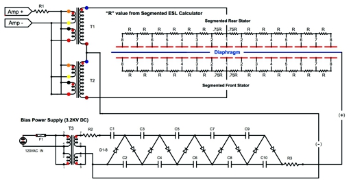
Electrostatic Speakers with Wire Stators If you have any desire to build an electrostatic loudspeaker, this website is a must see.
Unity-Gain Phase Splitters
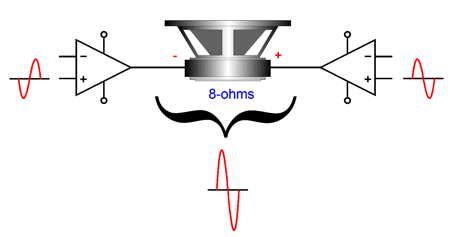
The answer was that many audiophiles were buying two identical stereo amplifiers and running them in bridge mode, which more than doubled their output power. (The math is that you get twice as many watts into an 8-ohm speaker as a single amplifier channel could put out into a 4-ohm load. Thus, if a nominally 100W stereo amplifier delivered 180W into a 4-ohm load, it would deliver 360W into an 8-ohm load in a bridge configuration; if it could deliver 200W, then it would deliver 400W into 8 ohms.) Not a bad answer. Indeed, I can imagine that some own power amplifiers with only balanced inputs and a unity-gain phase splitter would save the day. I asked to see the circuit. No go. Proprietary, top secret, for their eyes only. As they were far too possessive of their exclusive circuit to let me see it, I offered a simple solid-state alternative circuit.
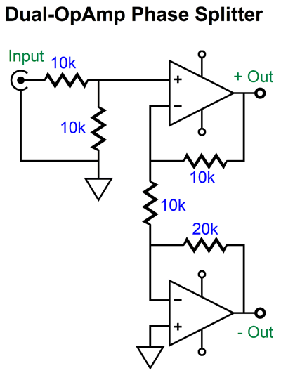
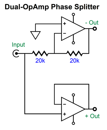
The two-resistor voltage divider at the input halves the input signal, but as both OpAmps deliver a gain of 1:2, we return to unity gain. Another version uses fewer resistors, but absolutely requires unity-gain stable OpAmps.
They didn't like solid-state circuits. I then drew several transformer-based alternatives, all of which were passive.
They didn't like having to use two signal transformers, which were extremely expensive. I then drew two single transformer-per-channel circuits.
Note that all the transformers see a load resistance. This is critical for optimal performance. In these examples, I assumed that 20k was the optimal load resistance, but the best practice is to read the data sheet for the transformer and use the value that the transformer company recommends. Let's say that 20k was the right value. Next, we must calculate the amplifier's input impedance into the mix. For example, if the amplifier's input impedance was 20k, then we would NOT use any load resistor, as none was needed. If its impedance was 47k, then we would use a 34.8k load resistor, as 348k||47k equals 20k. They wanted a tube-based circuit, not transformers. I then dew a split-load phase splitter.
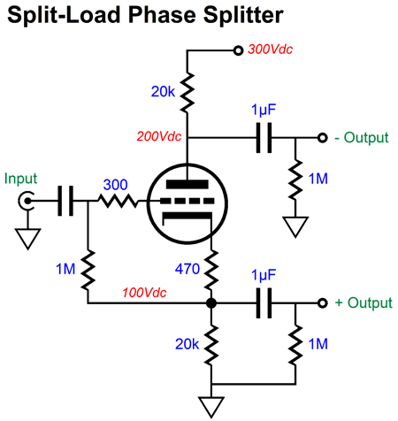
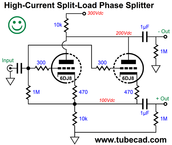
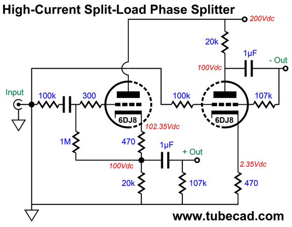
No, no, no, I was told. Why not? I was informed that the dissimilar output impedances made that circuit worthless. I explained that the output impedance didn't matter, as long as each phase output saw the same load resistance and capacitance, the result would be perfect balance up to truly ultra-high frequencies. I wasn't believed, besides the circuit could not deliver enough current. (I assume that they must have had a 12AX7 in mind, as they had mentioned it and voiced their preference for the 6DJ8.) I pointed out that two high-current triodes could be used in parallel.
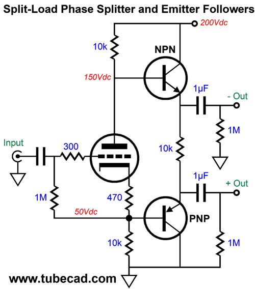
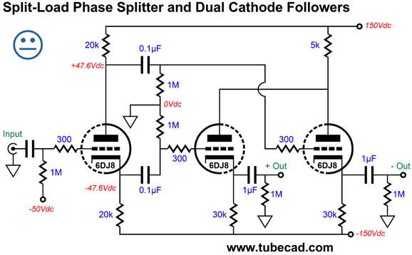
They were not convinced it would work at all, as they had never seen two triodes being used that way, besides the dissimilar output impedances were lowered but not made equal. I then drew a hybrid circuit, which could deliver high current and presented equal output impedances.
They didn't like transistors, besides they wanted to run a lower B+ voltage. My next drawing puzzled everyone.
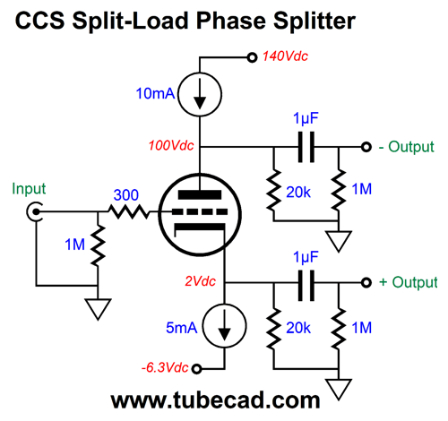
The two constant-current sources do a great job at improving the PSRR and they allow a much lower B+ voltage; in addition, there's no need for an input coupling capacitor. Note the differing CCS currents, with 10mA for the top CCS, as it sees two paths to ground, i.e. the triode and the 20k resistor. As far as the triode's plate and cathode are concerned, they are loaded only by 20k resistors. Apparently, no solid-state constant-current sources were allowed. I still believe that this is a dang clever circuit, as normally it is a bad practice to place two constant-current source in series with each other. In this circuit, however, the two 20k resistors save the day. In addition, we can power the tube's heater element with the -6.3Vdc power-supply rail. Well my patience was exhausted at this point, so I was about to bid them good luck and leave, as I was due back in the land of sanity and reality, when I was begrudgingly shown the top-secret schematic. It looked something like this, but poorly stretched out.
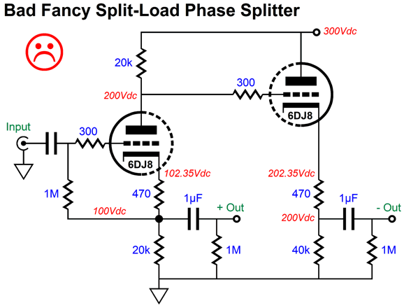
I was told that this genius circuit overcame the huge problem the split-load phase splitter's the dissimilar output impedances. Its only imperfection was that it didn't work when connected to a stereo power amplifier, but that it did work well when connected to a scope. They asked if I could fix it and said, no; in fact, no one could. I pointed out that the topology was fundamentally flawed. They insisted that it was the work of genius. (And some wonder why I drink.) First, the output impedances are not equal, as the inverting output presents a lower impedance than the non-inverting output impedance. Second, the amplifier's input impedance must throw the unity-gain off; and if the interconnect presents a high capacitance, the frequency response would also be skewed unequally between outputs. Imagine a stereo power amplifier with an input impedance of 600 ohms. The input triode will now see a cathode resistance of 1052 ohms, but its plate load is still 20k, so the split-load phase splitter has been transformed into a grounded-cathode amplifier, with gain at the plate and attenuation at the cathode. In short, the circuit was heroically dumb, in spite of it being pure genius, that it was at best half-assed. What would a full complement of cheeks look like? I then drew my final schematic before leaving.
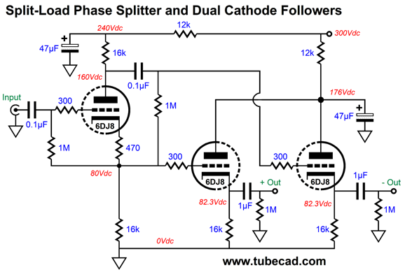
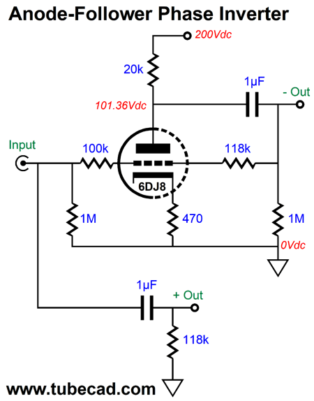
This circuit did offer equal output impedances and equal frequency response from both outputs. They didn't like the 300Vdc B+ voltage. As far as I know, they never did release an unbalanced-to-balanced product. Let's now leave ancient history behind and examine some alternative circuits. Here is a simple alternative to the split-load phase splitter (by the way the split-load phase splitter works just fine).
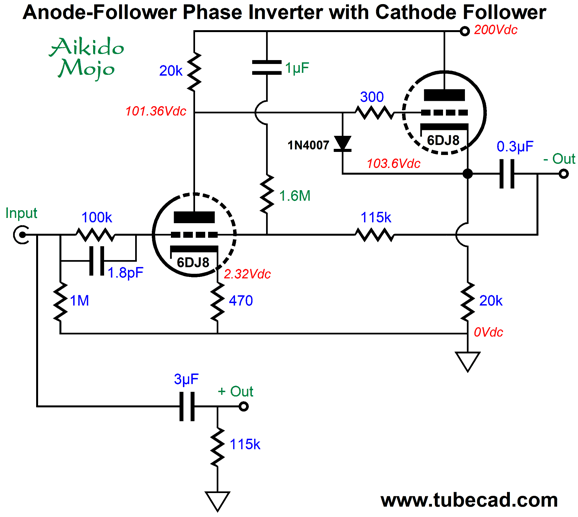
The anode follower offers both unity-gain and phase inversion and a fairly low output impedance. The high-pass filter (the 1µF capacitor and 118k resistor) below it ensures that both amplifiers see the same phase shifts at low frequencies, which is critical in a bridge amplifier. All in all, not a bad circuit. Of course, we could get extra fancy.
There's a lot going on here. The biggest change is the addition of the cathode follower to the anode -follower circuit, which offers a much lower output impedance and makes the circuit far more load independent. The 1.8pF capacitor shunting the 100k resistor improves the circuit's high-frequency performance by undoing the Miller-effect capacitance interacting with the 100k resistor. The 1µF capacitor and 1.6M resistor inject some Aikido mojo, greatly improving the PSRR. Note the dissimilar output capacitor values. Since the 0.3µF is within the anode follower's negative feedback loop, it value is effectively magnified. Also note the increase in the high-pass filter capacitor, which was needed to establish equal low-frequency bandwidth. One potential problem is that the signal source, say, an old tube-based FM tuner or wimpy line-stage amplifier perhaps, might use too small of an output coupling capacitor, which would imbalance the signals going to the power amplifiers. One workaround would be to use two active outputs.
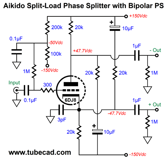
The triode on the left is configured as a cathode follower; the triode on the right, an anode follower, which inverts its input signal at its output. The 100k input resistor to the cathode follower balances the high-frequency bandwidth between outputs. Yes, we could have forgone this resistor and used a 1.8pF capacitor across the anode follower's 100k input resistor, but I wanted to show both ways of restoring balance at high frequencies. Speaking of balance, let's look at a variation on that last circuit I drew for the high-end audio company. Note the bipolar power supply. The secondary goal was an enhanced PSRR. The primary goal was excellent output-signal balance, which the circuit achieves.
Now, PSRR can get tricky with balanced circuits. Here's why: the underlining assumption is that the following balanced gear receiving the balanced input signal offers a high common-mode rejection (CMRR). CMRR delivers the sonic goods, as it means that signals that are in phase and common to both phases of the input signal will be ignored, as only differences are acknowledged as being signal to be amplified. Hum is often a common-mode signal. For example, if both balanced outputs share the same 10mV of in phase ripple relative to 1V of ripple at the B+ voltage, we say that the PSRR is -40dB, as only 1/100th of the ripple appears at the outputs. Now if the following balanced equipment offers a high CMRR, the ripple will be largely ignored, perhaps entirely. What if each balanced output puts out 10mV of ripple, but in opposite phases? Not good. Now the ripple will effectively be treated as 20mV of signal to be amplified. If the bridge amplifier's gain is 1:30, the 20mV will become 0.6V of ripple across the loudspeaker. Not good. Here is another possible outcome: one phase holds 30mV of ripple and the other phase holds 20mV of ripple, with both ripples being perfectly in phase. The difference of 10mV means that the next balanced amplifier will see the ripple as 10mV of signal to be amplified. In other words, it would be far better if both phases presented 30mV of in-phase ripple. Well, in this circuit, we see such an imbalance of in-phase ripple. So how do we get to either no ripple or at least equal in-phase ripple? A great question; I am so glad you asked. We get sneaky.
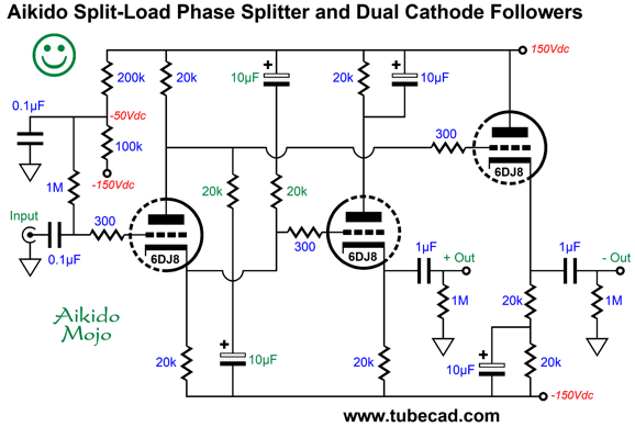
First, is there anywhere else that you would see such a circuit? I don't think you can, but I would love to be proved wrong. To see how the Aikido mojo obtains, imagine that the input triode wasn't there. In its absence, what AC input signal would each cathode follower see at is grid? Answer: assuming equal and out-of-phase ripple on both bipolar power supply rails, the AC signal would be zero, as the four 20k resistors define two sets of two-resistor voltage dividers, each with an AC signal division of 1/2. What is the DC voltage at the midpoint of two equal resistors tied in series and attached at one to +1V and -1V at the other end? Zero Volts.
Okay, put the input triode back into the circuit. Since each two-resistor voltage divider places two 20k impedances in parallel, the input triode sees a plate load impedance of 10k, as does its cathode. In other words, the phase splitter still provides equal, but out of phase output signals. As far as the input triode is concerned it is nested in a ripple-free bubble. Each cathode follower triode sees the same 100V cathode-to-plate voltage, well roughly 100V. The result is that the PSRR for both phase outputs comes in at about -32dB in SPICE simulations. More importantly, the rippled leaked at each phase output is equal and in phase, which will allow the following high-CMRR amplifier to ignore the ripple.
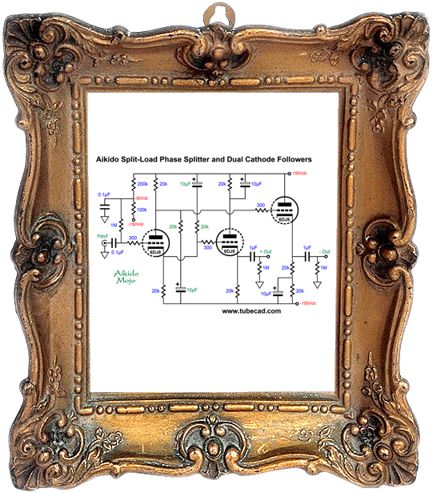
I love the look of this topology, as it is so damn balanced. In fact, I should make a fine print of it and frame it. I have been meaning to do something like this for decades now, but wife-acceptance factor is a steep cliff to climb. By the way, we can increase the PSRR even further, but at the cost of a higher output impedance, which may not be important with power amplifiers with input impedances higher than 10k.
Note the added 510-ohm cathode resistors. These resistors force a deep PSRR null. The output impedance will be about 600 ohms. Also note the 12AT7/ECC81 split-load phase splitter triode. The 12AT7's high mu of 60 gets us closer to unity gain. In addition, the 12AT7 and 6DJ8 make a fun pairing, as the two differing sonic signatures blend into a more neutral combination. Okay, I should mention that if you plan on driving 600-ohm loads, then the output coupling capacitor must be at least 15µF in value. I should also mention that if the driven amplifier's input impedance is closer to something such as 30k to 100k, then you really do not need the cathode followers.
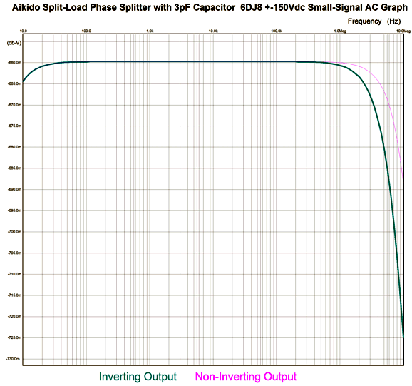
The distortion is low and the bandwidth wide and the PSRR stellar and the balance perfect. Of course, this assumes tightly matched resistors. The 3pF capacitor prevents peaking and sagging at frequencies above 1MHz and brings both phases in line in terms of high-frequency bandwidth. Here is the frequency graph with the 3pF capacitor.
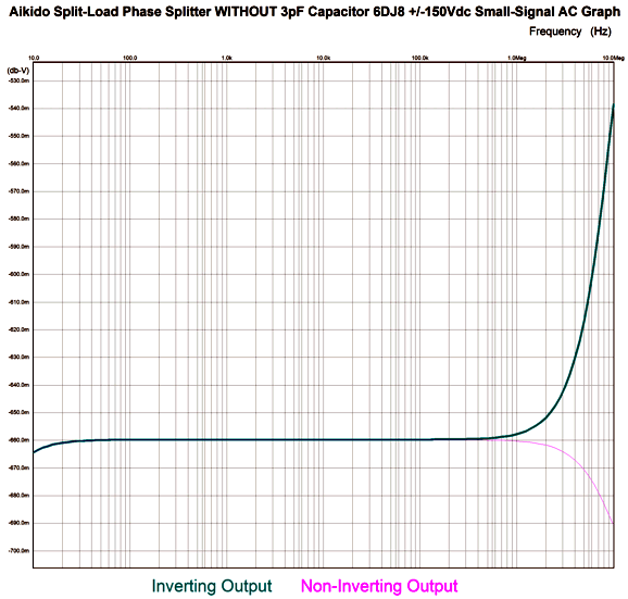
Now, let's look at what we get without the capacitor.
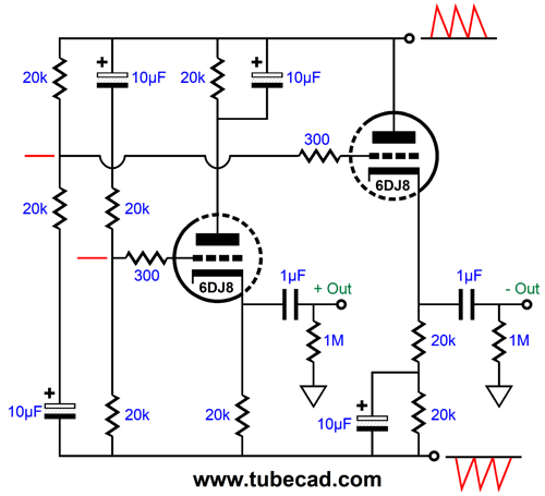
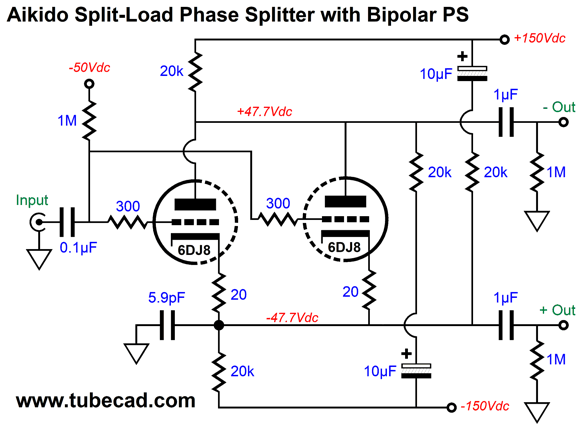
The 10µF capacitors can be increased in value, as 10µF was just a starting value. (I would probably use 100µF capacitors.) We can even double up on the triodes.
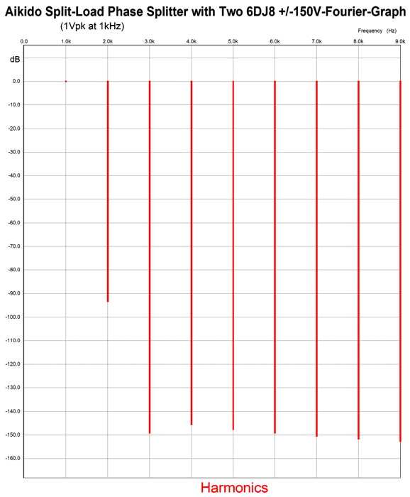
Note the additional 20-ohm cathode resistors and the 5.9pF capacitor and the 100µF capacitors. The double current flow will help drive long high-capacitance interconnects. The 20-ohm cathode resistors are there to help equalize current flow between the two triodes. Here is the SPICE-generated Fourier graph.
As you can see the distortion is quite low, with only the second harmonics coming in strong; moreover, look at the extremely attenuated 3rd harmonic.
More Crazy Speaker Ideas
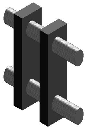
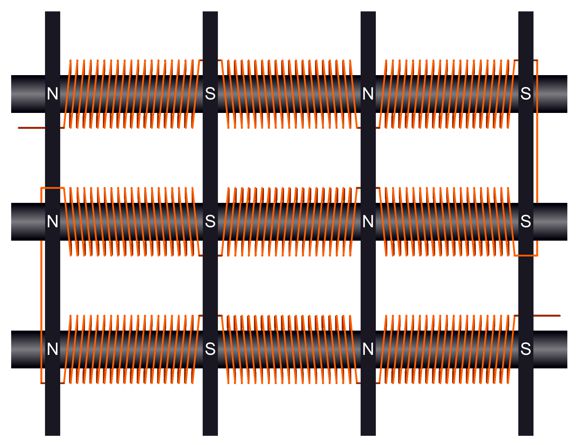
Of readily available metals, iron makes the electromagnet core, as it offers very high permeability, which is the measure of magnetization resulting from an applied magnetic field. Next, we need copper wire, lots of it. The idea is that we will wind the wire in one direction over an inner bar segment, then wind in the opposite direction on the next bar segment.
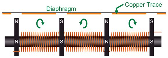
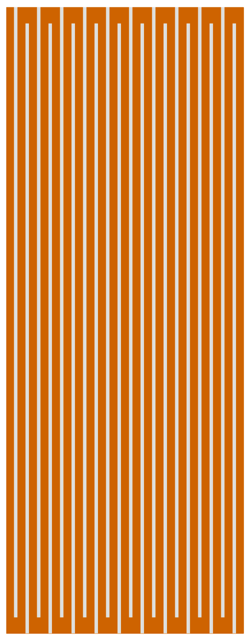
This is the top view, where we see the diaphragm edge on and the iron grating placed near it. Let's now look at the front view.
You get the idea: we fill up the space surrounding the exposed iron cylindrical bars. If we used 1,000 fet of 16-gauge copper magnet wire, the DC resistance would be close to 4 ohms. If we attach the ends of the wire to a 12Vdc power supply, 3A of current will flow. The diaphragm must hold a zigzag pattern of copper trace.
What we have done is replace the long strips of bar magnets with an electromagnet, which will require a DC voltage supply to energize the coils of wire. By varying the DC voltage, we vary the magnetic field strength, which means we could vary the electrical Q of the speaker. The total Q of the speaker is equal to the Qes in parallel with the Qms, the mechanical system Q.
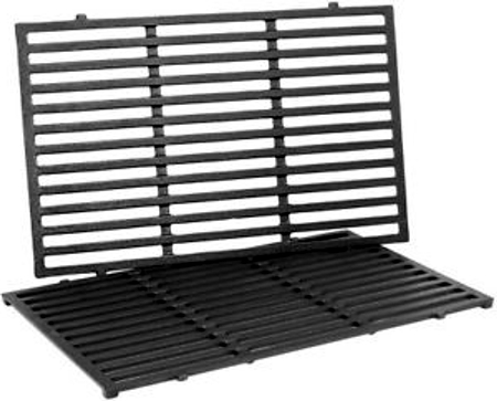
We could try this idea out with a cast-iron barbeque grill or the iron gratings made covering drainage holes.
//JRB
User Guides for GlassWare Software
For those of you who still have old computers running Windows XP (32-bit) or any other Windows 32-bit OS, I have setup the download availability of my old old standards: Tube CAD, SE Amp CAD, and Audio Gadgets. The downloads are at the GlassWare-Yahoo store and the price is only $9.95 for each program. http://glass-ware.stores.yahoo.net/adsoffromgla.html So many have asked that I had to do it. WARNING: THESE THREE PROGRAMS WILL NOT RUN UNDER VISTA 64-Bit or WINDOWS 7, 8, and 10 if the OS is not 32-bit or if the OS is 64-bit. I do plan on remaking all of these programs into 64-bit versions, but it will be a huge ordeal, as programming requires vast chunks of noise-free time, something very rare with children running about. Ideally, I would love to come out with versions that run on iPads and Android-OS tablets.
|
I know that some readers wish to avoid Patreon, so here is a PayPal donate button instead. Thanks. John Broskie
John Gives
Special Thanks to the Special 85
I am truly stunned and appreciative of their support. In addition I want to thank the following patrons:
All of your support makes a big difference. I would love to arrive at the point where creating my posts was my top priority of the day, not something that I have to steal time from other obligations to do. The more support I get, the higher up these posts move up in deserving attention.
If you have been reading my posts, you know that my lifetime goal is reaching post number one thousand. I have 467 more to go. My second goal is to gather 100 patrons. I have 15 patrons to go. Help me get there.
Only $9.95
The Tube CAD Journal's first companion program, TCJ Filter Design lets you design a filter or crossover (passive, OpAmp or tube) without having to check out thick textbooks from the library and without having to breakout the scientific calculator. This program's goal is to provide a quick and easy display not only of the frequency response, but also of the resistor and capacitor values for a passive and active filters and crossovers. TCJ Filter Design is easy to use, but not lightweight, holding over 60 different filter topologies and up to four filter alignments: While the program's main concern is active filters, solid-state and tube, it also does passive filters. In fact, it can be used to calculate passive crossovers for use with speakers by entering 8 ohms as the terminating resistance. Click on the image below to see the full screen capture.
Tube crossovers are a major part of this program; both buffered and un-buffered tube based filters along with mono-polar and bipolar power supply topologies are covered. Available on a CD-ROM and a downloadable version (4 Megabytes). Download or CD ROM
|
|||


| www.tubecad.com Copyright © 1999-2021 GlassWare All Rights Reserved |