| John Broskie's Guide to Tube Circuit Analysis & Design |
03 June 2021 Post Number 537
High-Gain Tube-Based Phono Preamp My second experiment… Experiment, what experiment? What do experiments have to do with audio? Audiophiles in pursuit of the Supreme Sound seldom do experiments; instead, they pray and beseech Heaven with their useless supplications, they make huge cash sacrifices, they consulate sacred texts (Stereophile and The Absolute Sound), they seek priests (high-end audio salon salesmen) to act as a mediatory agents between their audio system and the manufacturers of audio Nirvana—but they seldom experiment. I have seen this too many times to recount. For example, I offer the suggestion that we try changing one variable, such as changing the VTA of a phono cartridge or toe in the speakers a tad more, but I am met with stern disapproval. I once recommended that my friend try flipping the phase on his loudspeaker's midrange. He was as horrified as if I had suggested that we try our hands at amateur brain surgery. Here is the full story from post 321 :
Well, my second experiment was to use a 40dB phono preamp and an especially-hot line-stage amplifier to see if we could pass on the burden of more gain to the line-stage amplifier. Here is the logic and math: a low-output moving coil phono cartridge needs 20dB more gain than high-output cartridges, so we can add either a step-up signal transformer with a 1:10 winding ratio or we can use a phono preamp 20dB hotter (60dB rather than 40dB) or we can ask the line-stage amplifier to add the needed 20dB of extra signal gain. What about playing a tape machine or DAC or CD player or FM tuner? Won't the extra-hot line-stage amplifier's higher gain cause problems? It would, but we could put in place -20dB two-resistor voltage attenuators at each of the RCA jacks, save for the phono input jacks.
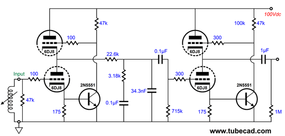
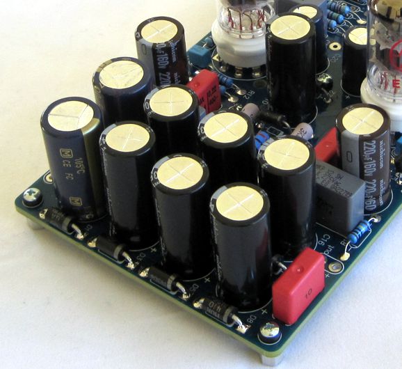
How did this experiment turn out? Not bad. Surprisingly good, in fact. We had all the gain we needed and the little 40dB phono preamp played like a champ. The circuit is an interesting one and is based on my super-triode idea.
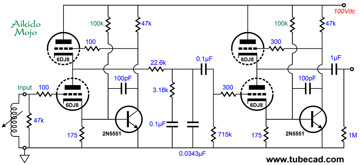
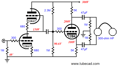
The NPN transistor reads the current flow through the input triode by monitoring the voltage drop across the 175-ohm cathode resistor and strives to ensure that the current flow remains constant, which in the face of a varying input signal can only be accomplished by varying its plate voltage by a factor of the triode's amplification factor (mu). The top triode acts like a cathode follower and the result is a gain stage with a gain equal to the triodes used and an exceedingly low output impedance. What is truly amazing is that the B+ voltage is only 100Vdc. I added some Aikido mojo in the form of the 150k resistors and some ultra-high-frequency stability in the form of the 100pF capacitors.
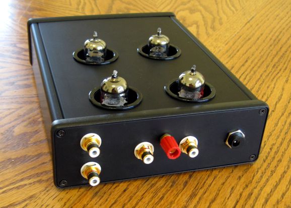
This tiny phono stage runs off a 12Vac wallwart.
Okay, having made my experiments, my conclusion is still that a good step-up transformer is the best route to travel with a tube-based system, as the transformer nicely sidesteps the problem of Johnson–Nyquist noise (thermal noise) that the tubes and the high-resistor values used in a tube-based preamp to which must give rise. As high-quality MC step-up transformers are not cheap, however, one possible workaround would be a simple OpAmp-based 20dB linear pre-preamp amplifier. I would use two rechargeable 9V batteries, which when in standby mode would see a trickle of current to keep them charged; while playing, however, the external DC wallwart would be detached.
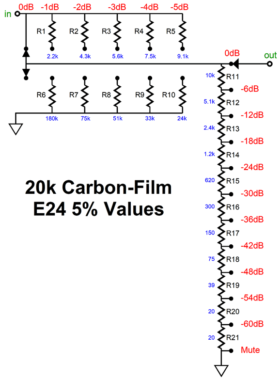
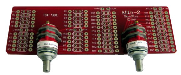
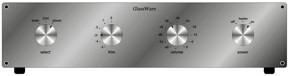
Mono Balanced Attenuator
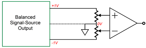
Instead of left and right channels of signal, we simply connect the plus and the minus of one channel of balanced input signal as if it were left and right channels of unbalanced stereo. The attenuator does not care where the signal came from. Unlike the old BM-1 balanced mono attenuator, the Attn-2 attenuator presents a constant input impedance. Does that matter? It certainly can if input filters or an input signal transformer is used. In addition, the gold contacts are the best type for delicate audio signals in a sealed switch.
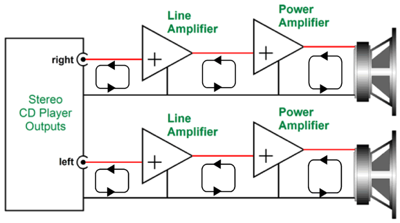
Many like the idea of dual mono phono stages or line-stage amplifiers, as they offer the ultimate in signal separation. Or do they? They certainly do when driving dual mono power amplifiers. In most unbalanced stereo systems, i.e. RCA-jack setups, one channel's signal usually takes two current paths back to the source, not one.
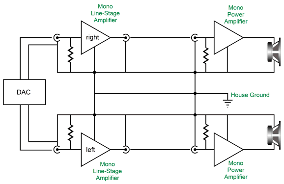
Signal in on one channel stays in one channel. Alas, if the audio signal's ground attaches to the house ground, then we no longer have dual mono anything.
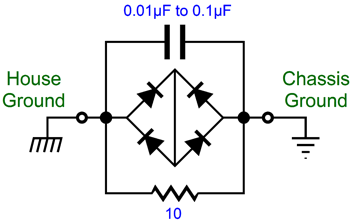
What we have done is "ground" all the seemingly independent mono pieces of equipment together through the wiring in your house. The workaround is to add a House-Ground circuit to each powered device.
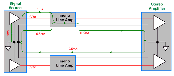
The House-Ground circuit provides the safety of using the house ground, but introduces enough resistance to limit the current circulations through the house wiring. Another example of failed dual mono consists of using dual-mono unbalanced line-stage amplifiers and a stereo power amplifier.
It looks dual mono, in terms of AC voltages, but not in terms of AC currents. Signal appeared only in the top channel, yet the current traveled equally in both channel's interconnect. Why? The return current takes all the paths provided to it. The result is that each channel's ground lead sees the same current flow, as both provide the same resistance back to the signal source. The makers of expensive interconnects assume that only one channel exists in their shiny ads, which show the perfect balance of construction and signal flow, the hot wire in a complementary position relative to its ground wire, like two snakes mating. Reality is under no obligation, however, to conform to advertising copy or illustrations. AC voltages can exist in only one channel, but not AC current flows in a stereo setup. In short, dual-mono line-stage amplifiers only make sense when driving dual-mono power amplifiers—when unbalanced signals are used.
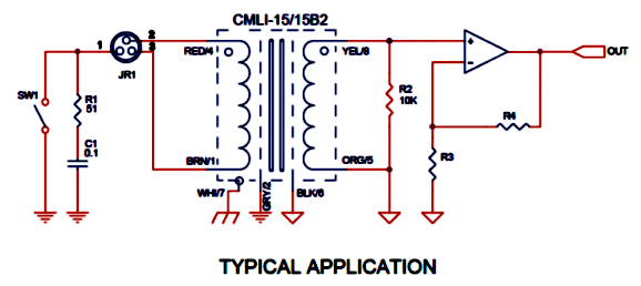
Balanced setups, if properly designed, sidestep this problem, as the AC signals do not travel through the ground leads or shields. The plus and minus signal wires see anti-phase voltage and current flows, while the ground wire (if there is one) and the grounded shield see neither. Thus, dual-mono balanced line-stage amplifiers can drive a balanced stereo power amplifier with no problems—as long as the signal source is also balanced. Ideally in a balanced system, the connection between the signal ground and the receiving equipment's ground will be through a 51-ohm resistor in series with a 0.01µF capacitor, which is used to terminate the interconnect's internal shield, preventing it from becoming an antenna to RFI; pin-1 on the XLR jacks should either attach to the chassis or be left floating.
The huge problem is many balanced cables attach the shield to both plugs cases. A nightmare. Neutrik makes a wonderful solution in their 3-pole EMC-XLR cable connectors (NC3FXX-EMC and NC3MXX-EMC).
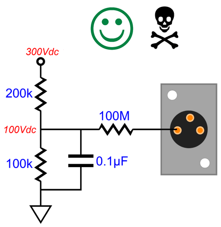
WARNING, here is an idea only for the most skilled electrical practitioners. With the special not-grounded Neutrik male and female connectors, we could use the Pin-1 ground wire to create a polarized balanced cable. How so? At the signal source, say, a balanced tube-based phono stage, we could set up a two-resistor voltage divider that would reduce the B+ voltage to 100Vdc. Then we would place a 100M resistor in series with the divider's output, terminating the resistor at the male XLR jack on the phono preamp's chassis. In the balanced line-amplifier chassis, pin-1 is left floating.
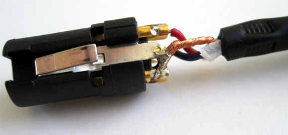
What if someone plugs in a regular balanced cable that attaches both the internal shield and the ground wire to pin-1 at both ends? The 100-megaohm resistor gets shorted to ground, assuming that the chassis is grounded. The only danger I can see is if someone touched the male prongs with the 100V polarizing voltage. Obviously, the current is greatly limited by the 100M resistor, but you would still feel a shock. This idea assumes that three wires are found in the cable, which is not always the case. Here is a typical balanced cable's female end.
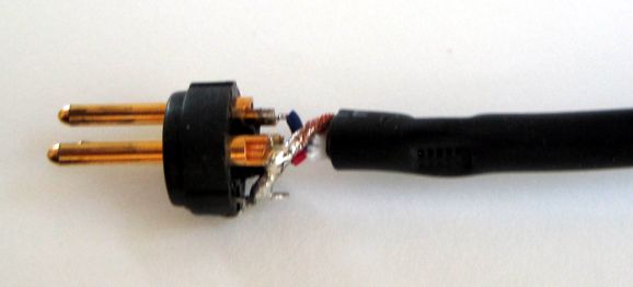
Note how only two twisted wires are shielded and that shield is soldered to both pin-1 and the shell. Here is the male end.
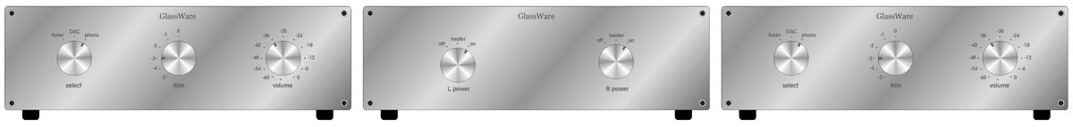
It's hard to see, but once again the shield attaches to both pin-1 and the shell, which will connect the two chassis together. What I do is break the shied's connection to the shell and solder a tiny ceramic capacitor from the shield to the shell, leaving pin-1 unattached. And just like that my hum problems diappeared. Building two mono balanced line-stage amplifiers would be easy enough. We could use a Select-2 or Select-5 signal selector switches, as they treat each channel's ground completely separately. We add a Attn-2 stereo mono balanced stepped attenuator and the stereo line amplifier of our choice and a suitable power supply and enclosure.
I would build a three-enclosure assembly, with an enclosure for the two separate power supplies. Why? House ground issues. Ideally, the shared power supply enclosure would be hard wired to the house ground, with each channel's floating power supply connected to the house ground through its own House Ground circuit. In addition, we can place the power supply chassis away from the balanced mono enclosures. I would use two power transformers and two power switches, but only one AC power receptacle and fuse.
CMRR without a Constant-Current Source
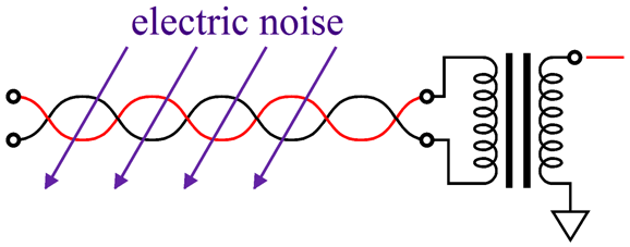
A transformer is an intrinsically high CMRR device, as only differences are coupled to the secondary. A constant-current source loading the coupled cathodes allows a differential amplifier to ignore common-mode signals at the two input grids.
The downsides to signal transformers are high cost, limited bandwidth, and potential hum problems if the transformer is not sufficiently well shielded. The downsides to constant-current sources are that they are usually solid-state devices and that they require a voltage drop to work, which with solid-state constant-current sources can be as little as a few volts; with a tube-based constant-current source, 100 volts.
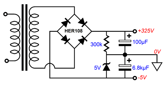
The problem this circuit faces is that the constant-current source is voltage starved. In addition, this circuit offers nearly no PSRR. In other words, just about all of the power-supply noise will appear on the outputs. Fixing the limited voltage for the CCS can easily be fixed with a low-voltage negative power-supply rail.
What if your power transfer does not offer a low-voltage tap? Here is a workaround.
The 5V zener creates a virtual negative rail. If the transformer holds a center-tap, then we would use this topology:
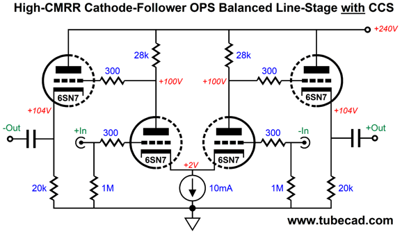
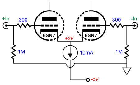
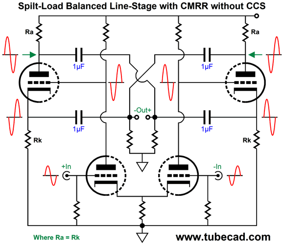
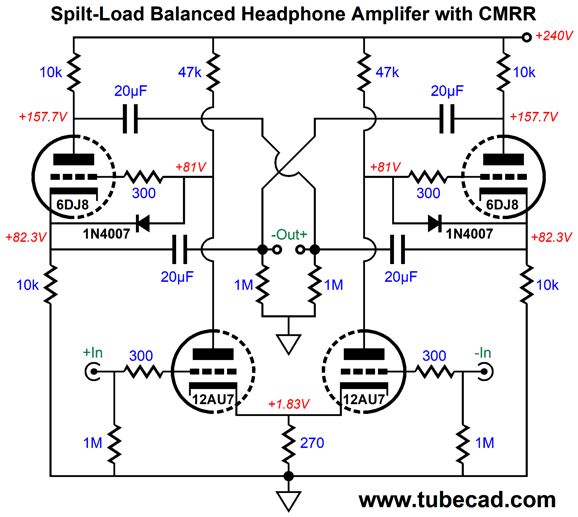
Well, is it possible to achieve CMRR without using either a signal transformer or a constant-current source? Yes, as it can think up three possible circuits. The first is that this circuit uses just two twin-triode tubes per channel. The input stage is a simple long-tail differential amplifier with a very short tail indeed, as no negative power-supply rail is used. The second stage consists of two split-load phase splitters. Here is an example of crisscrossed two split-load phase splitters from a previous post on balanced cathode followers .
Note the crisscrossing of the phase splitter outputs in the following circuit, which are harder to see. The four coupling capacitors lock the phase splitter cathode and plate resistors to each other, which produce some amazing results, such as a high-CMRR and excellent differential PSRR and low differential output impedance. The key word repeated in that last sentence was "differential." The PSRR relative to ground is fairly poor (only about 9.5dB), but relative to the balanced outputs it is exemplary, as the anti-phase outputs share exactly the same amount of power-supply noise in phase. In other words, the following balanced power amplifier's own high CMRR will ignore this common-mode signal.
What if the power amplifier's CMRR is weak? Then, we will have a problem and a different circuit should be used. (Most professional balanced power amplifiers offer very high common-mode rejection ratios.)
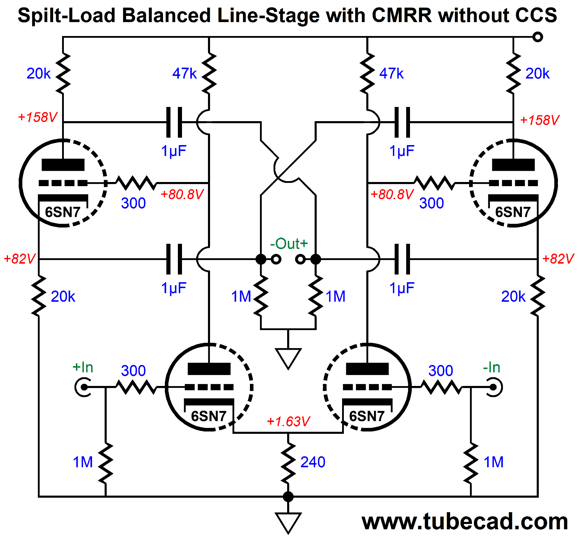
The low differential output impedance confuses even accomplished electrical engineers. With the 6SN7 tubes and relative to ground, the output impedance is about 3,000 ohms from each phase output; differentially, from inverting to non-inverting outputs, about 180 ohms. In other words, we could drive 300-ohm and 600-ohm headphones with balanced output with this circuit. Indeed, if we replace the 6SN7 with a 6DJ8 and lower the output stage's cathode and plate resistors to 10k, the differential output impedance is below 50 ohms. In addition, as headphone drivers are intrinsically differential electrical devices, their CMMR is near infinite, which will make the resulting effective PSRR near infinite.
By the way, the circuit's balanced operation is so fine that we can ground one input and drive the other with the input signal and still achieve near-perfect output balance. Is that a feature? Oh yes. Let's say that the balanced input signal is not as balanced as it should be. (Under an ideal setup, this would be impossible, but things can go wrong.) All that happens is that we get either a bit more or a bit less gain than we expected. With one grounded input, the gain halves. In other words, this circuit can double as an unbalanced-to-balanced converter (or phase splitter), which would allow easy selection of phasing. In other words, by selecting which input to ground and which to drive with an unbalanced input signal, we can select between either inverting or non-inverting output. Moreover, we could use the grounded input as a negative feedback input.
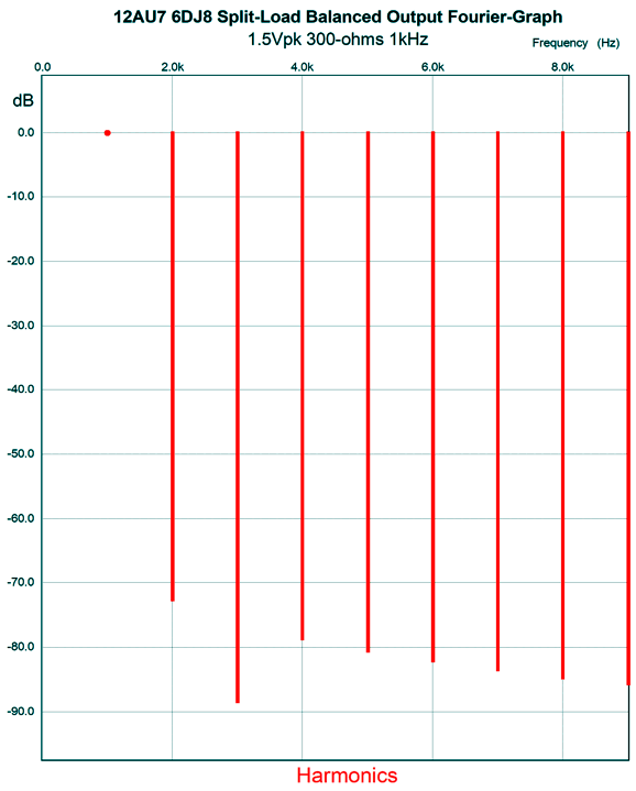
The only missing parts are two 1N4007 safety diodes to protect the split-load phase splitter triodes at turn on from seeing a cathode-to-grid differential voltage of 240Vdc. With the diodes in place, the maximum cathode-to-grid differential voltage is about 0.7V; in other words, the grid can never become more than 0.7 volts more positive than the cathode. Once the triodes are running hot, the diodes become reverse biased and effectively drop out of the circuit. With the 20µF coupling capacitors, the -3dB frequency with 300-ohm loads was below 20Hz. Here is what tickled me most about this design.
Note the strong suppression of the 3rd harmonic, so different from the typical push-pull output stage.
Version Two without CCS
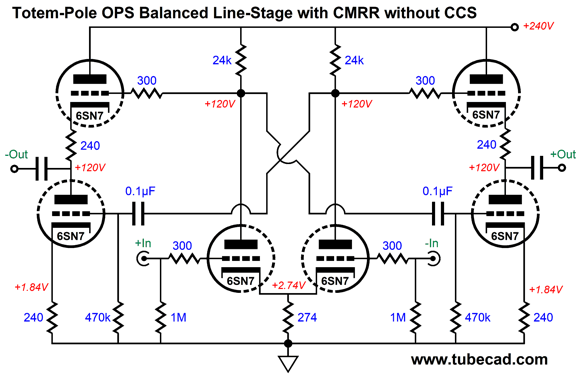
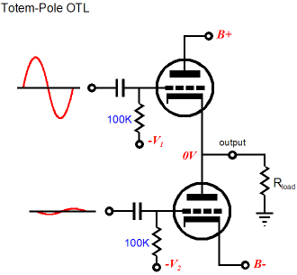
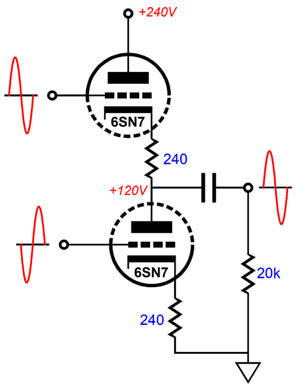
Paradoxically enough, the output stages are based on a poor OTL design. For over 20 years, I have been hammering the point that, unlike the circlotron, OTL output stages with a totem-pole configuration of one output tube atop another cannot receive the same magnitude of input signal for those output tubes, as the bottom tube will be grossly over driven, since its cathode is locked at either ground or the negative power-supply rail, whereas the top output tube's cathode moves with the output signal in phase with its grid signal. In short, the top output tube must see a larger input signal than the bottom output tube.
Obvious, if you think about it for a few seconds. So, why am I now recommending this flawed configuration here? Load resistance. The assumption here is that at least 20k of load resistance is expected, not an 8-ohm loudspeaker. Further assumptions are that the totem-pole output stages will use relatively high-value cathode resistors and that very little output voltage signal is demanded, say a volt or two. With these stipulations observed, the totem-pole configuration would work well in this application.
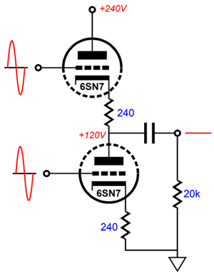
Effectively, the totem-pole configuration is a differential amplifier of sorts, as it requires anti-phase input signals. When faced with identical signals, i.e. both in magnitude and phase, nothing appears at the output.
Imagine arm wrestling with two equal men, who will win? Answer, neither.
Well, with both output tubes seeing the same positive input signal, both tubes will increase in current conduction equally, thereby canceling a voltage movement at the output. Of course, this assumes perfectly-linear output tubes, which do not exist. Triodes are easier to turn on than to turn off. This small imbalance is what gives single-ended power amplifiers their characteristic strong 2nd harmonic flavor. Thus, with four 6SN7 tubes, the circuit shown above realizes a CMRR of 86dB, which is more than a ten-thousand-fold reduction in output signal when the same signal is presented to both inputs. Not bad.
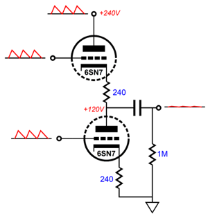
This circuit gets a nice boost in PSRR, as the cross-coupling of the output signal from the differential amplifier presents the same amount of leaked power-supply noise. Due to the triodes exhibiting a fairly low plate resistance, the power-supply-noise null is not perfect. In SPICE simulations, the PSRR came in at -27dB at 100Hz.
Differentially, from phase to phase of output, the equal magnitude and phase of the leaked power-supply noise results in an optimal balanced signal for a balanced power amplifier with a high CMRR. The circuit's output impedance with 6SN7 tubes came in at about 800 ohms, which is easily low enough for power amplifiers with an input impedance of 20k or higher. Headphones, on the other hand, cannot be driven cleanly, as the totem-pole configuration is not optimized to work into such a low load impedance. There is, however, a workaround.
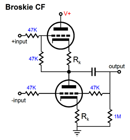
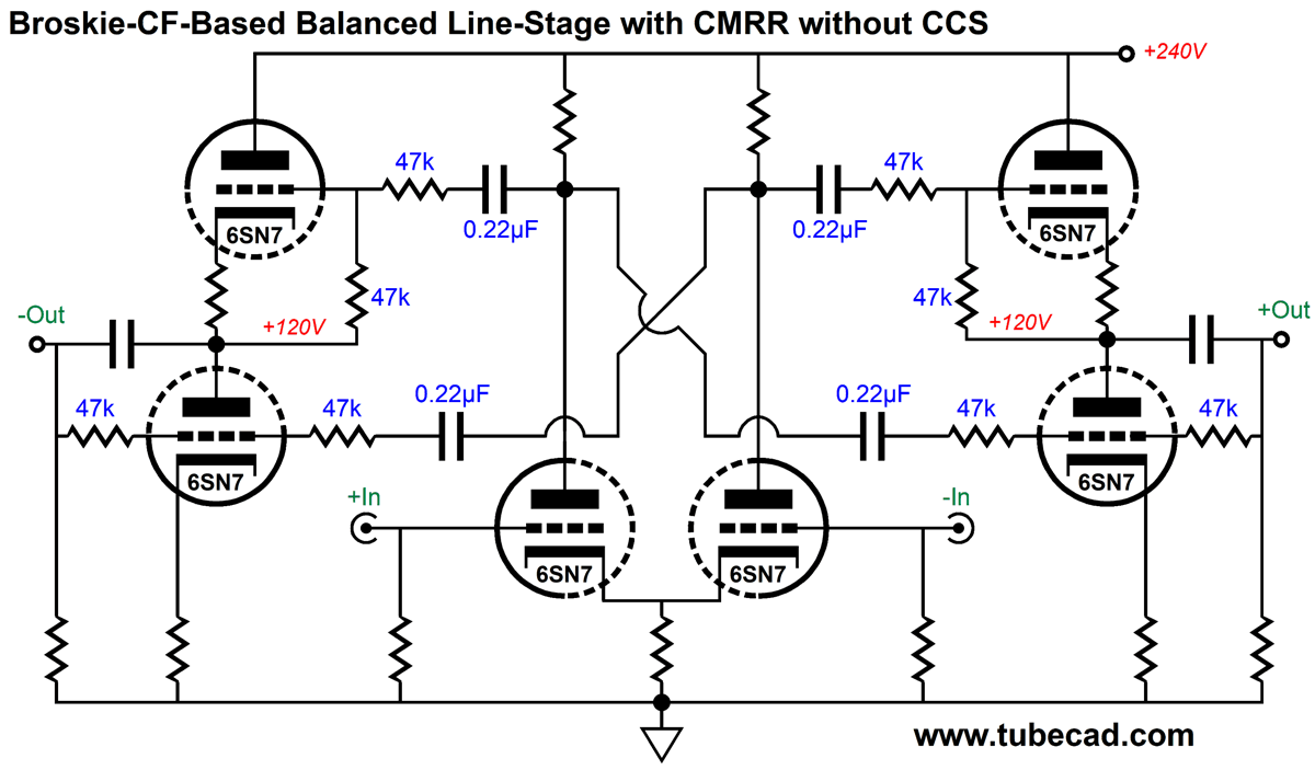
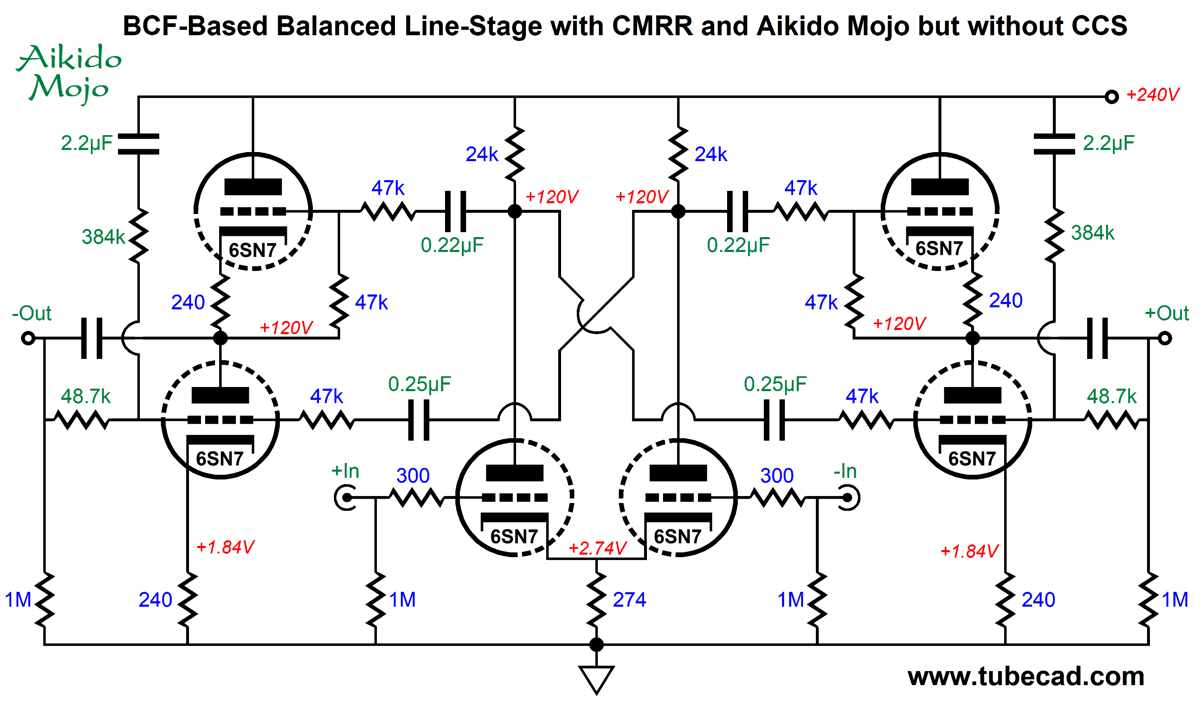
Version Three without CCS Why the change? Solid-state devices replaced signal transformers. In addition, few passive equalization and filter networks are used, both of which relied on the 600-ohm load impedance standard to work. Perhaps the old 600-ohm standard has resulted in many balanced power amplifiers presenting a lower input impedance than unbalanced power amplifiers, say 3k rather than 30k. Driving high-impedance headphones in a balanced fashion effectively halves the headphone impedance, so 300-ohm drivers appear as 150-ohm loads to each output, which means twice as large output coupling capacitors are needed and a circuit capable of working well into such a low load impedance. The solution is to replace the two totem-pole configurations in the last design with two Broskie cathode followers (BCF). The Broskie cathode follower also places one output tube atop another, but provides the means to balance both the current swings and output impedances of the two output triodes.
The balanced set if input signals enter and a single unbalanced output signal emerges. See TCJ October 1999 and Blog number 192 for more information on the Broskie cathode follower. When I created the circuit over twenty years ago, a recording engineer wrote to me and extolled the circuit's ability to drive his high-impedance headphones. I was convinced that he was wrong, so I quickly adapted my test-bench circuit to drive my 300-ohm Sennheiser headphones. Dang, he was right. Moreover, unlike the SRPP, White cathode follower, and the SRCFPP, the Broskie cathode follower is not load dependent. In other words, 300-ohm and 600-ohm headphones can be driven without changing any part values. In addition, this variation, unlike the previous version, can deliver huge output voltage swings without overdriving the output triodes.
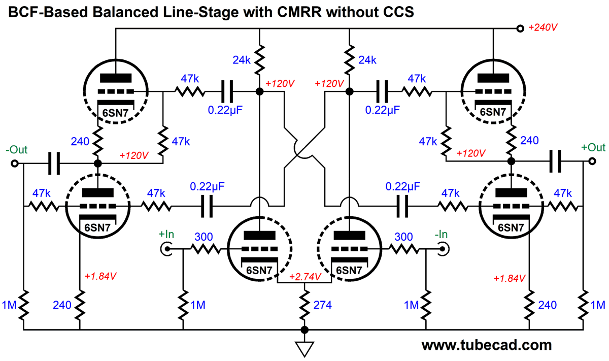
The differential input stage splits the B+ voltage and DC couples with the non-inverting inputs of the two Broskie cathode followers. The heater power supply should be referenced to one quarter of the B+ voltage. For example, if the B+ voltage is 240Vdc, then the heater power supply should be referenced to 60Vdc, which will result in both top and bottom triodes seeing a 60V cathode-to-heater voltage. Without tweaking resistor values, the CMRR came in at better than 40dB in SPICE simulations.
We can further tweak this circuit with the addition of some Aikido Mojo.
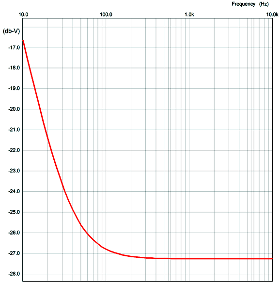
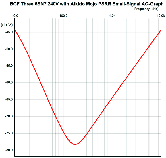
Here is the SPICE-generated graph for the PSRR versus the frequency.
Mercy. Mercy. Mercy. That's one deep null and centered right at the ripple frequencies.
Conclusion
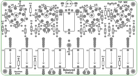
In fact, I so liked the design so much that I laid out a PCB to hold a stereo version of it with octal tubes.
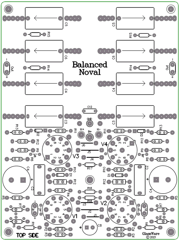
The output coupling capacitors take up so much room as so many are needed and large-value capacitors are fat. I also laid out a noval version, which was optimized for the added task of driving high-impedance headphones or 600-ohm balanced equipment, as we can find many more suitable output tubes in a noval envelope, such as the 6H30, 6DJ8, 5687, ECC99.
Both PCBs are 6 in by 8 in. The noval PCB holds two massive RC filters, one for each channel's B+ rail, whereas the octal PCB holds a singe 10µF decoupling capacitor that is shared by both channels.
Alas, I am in a bind, as I have paid last year's taxes and the accountant fees, which leaves me not enough money to order a new PCB production run that must necessarily be huge to get a decent price per PCB. Order one PCB and it will cost a fortune; order 10,000 of them and each will cost a few coins. Sadly, I am in the order 200 PCBs range. Time heals all wounds and most bank accounts.
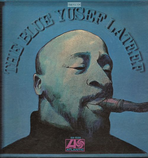
Music Recommendation: The Blue Yusef Lateef He played too many instruments to list, but was best known for his saxophone and flute playing. He had played with all the jazz greats, such as Cannonball Adderley, Art Blakey, Donald Bird, Paul Chambers, Dizzy Gillespie… It's a long list. I have been a big fan of his work for at least half a century. My father delighted in hearing Eastern and Middle-Eastern music and instruments, especially when combined with American Jazz. Thus, Lateef's 1957's album, Prayer to the East, and his 1961's album, Eastern Sounds, spun on our living room's record player frequently. I started my own Lateef collection with his 1968 album, The Blue Yusef Lateef. I still love it. The Blue Yusef Lateef is a concept album that explores the blues from many different perspectives, viewpoints, directions…. You haven't heard the album until you have heard the entire album. Although not an audiophile demo album, the sound does have its moments. In other words, this is not an album to test the extension of your subwoofers or super tweeters, but to thrill your soul. Give it a listen. Both Tidal and Amazon Music streaming music services offer many of Lateef's albums. Amazon even offers a 24-bit/192kHz version of his Little Symphony, wherein he plays all the instruments; yes, a one-man symphony.
//JRB
Very few can imagine just how much hard work is required to make one of my posts. If you have any sort of inkling or intuition of what is involved, please think about supporting me at Patreon.
User Guides for GlassWare Software
For those of you who still have old computers running Windows XP (32-bit) or any other Windows 32-bit OS, I have setup the download availability of my old old standards: Tube CAD, SE Amp CAD, and Audio Gadgets. The downloads are at the GlassWare-Yahoo store and the price is only $9.95 for each program. http://glass-ware.stores.yahoo.net/adsoffromgla.html So many have asked that I had to do it. WARNING: THESE THREE PROGRAMS WILL NOT RUN UNDER VISTA 64-Bit or WINDOWS 7, 8, and 10 if the OS is not 32-bit or if the OS is 64-bit. I do plan on remaking all of these programs into 64-bit versions, but it will be a huge ordeal, as programming requires vast chunks of noise-free time, something very rare with children running about. Ideally, I would love to come out with versions that run on iPads and Android-OS tablets.
|
I know that some readers wish to avoid Patreon, so here is a PayPal donate button instead. Thanks. John Broskie
John Gives
Special Thanks to the Special 84
I am truly stunned and appreciative of their support. In addition I want to thank the following patrons:
All of your support makes a big difference. I would love to arrive at the point where creating my posts was my top priority of the day, not something that I have to steal time from other obligations to do. The more support I get, the higher up these posts move up in deserving attention.
If you have been reading my posts, you know that my lifetime goal is reaching post number one thousand. I have 463 more to go. My second goal is to gather 100 patrons. I have 16 patrons to go. Help me get there.
Only $9.95
The Tube CAD Journal's first companion program, TCJ Filter Design lets you design a filter or crossover (passive, OpAmp or tube) without having to check out thick textbooks from the library and without having to breakout the scientific calculator. This program's goal is to provide a quick and easy display not only of the frequency response, but also of the resistor and capacitor values for a passive and active filters and crossovers. TCJ Filter Design is easy to use, but not lightweight, holding over 60 different filter topologies and up to four filter alignments: While the program's main concern is active filters, solid-state and tube, it also does passive filters. In fact, it can be used to calculate passive crossovers for use with speakers by entering 8 ohms as the terminating resistance. Click on the image below to see the full screen capture.
Tube crossovers are a major part of this program; both buffered and un-buffered tube based filters along with mono-polar and bipolar power supply topologies are covered. Available on a CD-ROM and a downloadable version (4 Megabytes). Download or CD ROM
|
|||
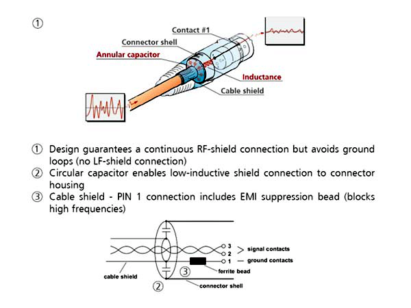 The shield makes no DC connection to the shell; instead, it is capacitively coupled to it. We do not have to do anything with Pin-1 in the line-stage amplifier's chassis. Okay, fasten your mental seatbelts.


| www.tubecad.com Copyright © 1999-2021 GlassWare All Rights Reserved |