| John Broskie's Guide to Tube Circuit Analysis & Design |
18 June 2021 Post Number 538
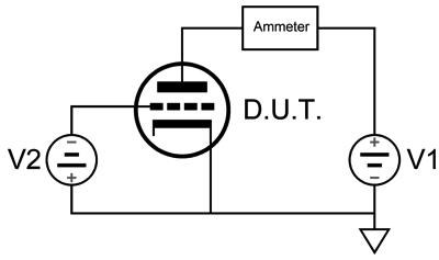
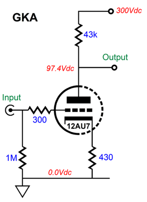
12AU7 SPICE Models Vs Reality
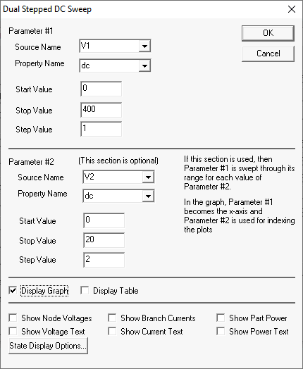
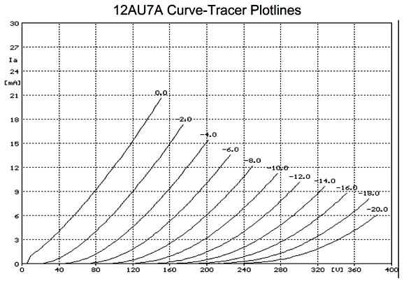
I didn't expect the 12AU7 SPICE model to match all that well. Why not? As I have pointed out many, many times before, all SPICE triode models are fundamentally flawed, as they all treat the triode as if it were a variable current source, which it simply isn't. A triode is variable resistance. In the absence of cathode-to-plate voltage, a triode draws zero current. This is not necessarily true with SPICE models, which often show triodes producing current much like batteries produce voltage. Therefore, any SPICE triode model that begins with "current = fancy math" is essentially off the tracks, as it should read, "resistance = fancy math." The 12AU7 SPICE model yielded some crazy results—more and crazier than I expected. First, let's look at the actual curve-tracer plate lines.
Of course, this set of plate curves applies only to one individual 12AU7. Nonetheless, it looks like a 12AU7. Four decades ago while searching through a college library's electrical-engineering books I found an amazing book. It was a collection of plate curves for many of the most popular tubes, such as the 12AX7 and 12BH7… What made it interesting was the way the curves were generated: rather than trace a set of plate curves for one triode, 10 triodes were wired in parallel and this grouping underwent curve tracing; afterwards, the current scale was divided by ten. In other words, the set of curves was an average of the ten individual triodes, so possibly not one triode matched the resulting curves, but the curves were fundamentally a more accurate representation of the triode in general. Now, let's look at the plate curves produced by the first 12AU7 SPICE model, overlaid upon the curve-tracer plots.
Not so good. Note that as we move away from the 0V plate line, the SPICE model progressively fails to match reality, as the model assumes a constant amplification factor. Bad as this is, it's actually worse, as I edited out the SPICE model's most egregious failing: increased current flow with greater negative grid voltages.
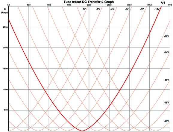
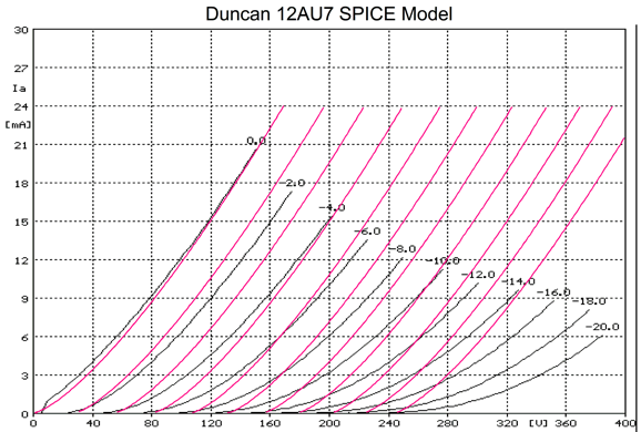
The -10V-grid-voltage plotline was made bold to show how the model egregiously screws up. An actual 12AU7 with a cathode-to-plate voltage of 0V and a grid voltage of -10V does not draw 27mA of plate current; it does not draw any current. This is the stuff from which perpetual-motion machines are made. What seems to have gone wrong is that the model attempted to account for positive-grid current flow but failed. I found two other 12AU7 SPICE models to test. The next is from Duncan Amps.
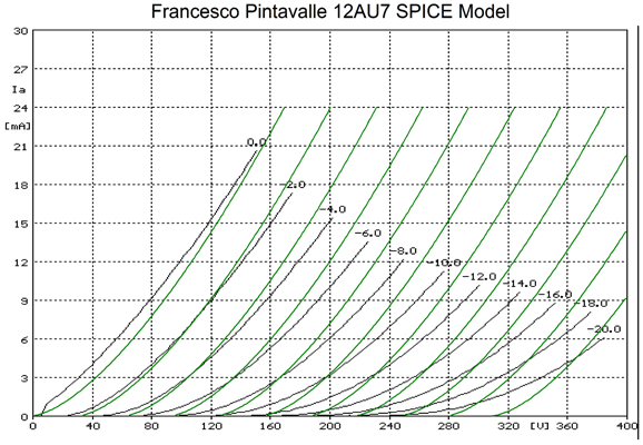
No insane folding back, but we do see the same assumption of a constant amplification factor. The next is by Francesco Pintavalle.
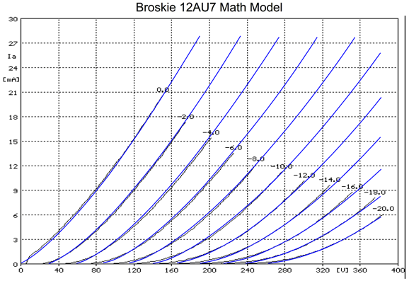
The resulting plate curves are much better than those by the previous SPICE model and, once again, we see the same assumption of a constant amplification factor. I decided to try my own 12AU7 math model and the results were satisfying.
My model tracks fairly well the curve-tracer plots, departing only slightly at the bottom, where the triode nears cutoff. Speaking of which, here is my triode-model formula:
Note how I based the formula on the famous Childs formula, but normalized (or referenced to) the grid voltage (Vg) and added three new variables, A, B, and C. Where the 12AU7 variables equal:
Why not use this math model in place of the existing SPICE models? I have tried, we all tried, when I worked on the B2-SPICE simulation program twenty years ago at Beige Bag Software. Essentially, to get my triode math model to work in the SPICE engine requires creating a new class of device within the SPICE source code, much like the existing MOSFET class, which would contain all the fundamental aspects of a triode, such as its functioning as a diode as current only flows from the cathode to the plate when the plate is more positive than the cathode. With an expanded SPICE source code, triode models would contain such features as the potential for positive-grid current flow and inverted operation, wherein we treat the grid as the plate and the plate as the grid. In addition, we would certainly find in the triode SPICE model the following line: resistance = fancy math.
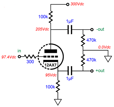
Another Split-Load Phase Splitter Version
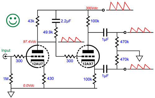
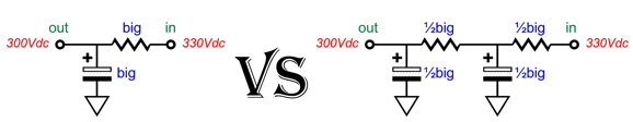
The circuit yields a gain of about 1:13 (22dB) and leaks about 28% of the power-supply noise at its output, which isn't enough to create a PSRR null in the following split-load phase splitter.
If the cathode resistor had been bypassed with a large-valued capacitor, the leaked power-supply noise would be even less.
Not good, as the split-load phase splitter needs to see something closer to 50% of the power-supply noise at its input to balance the PSRR from its two outputs.
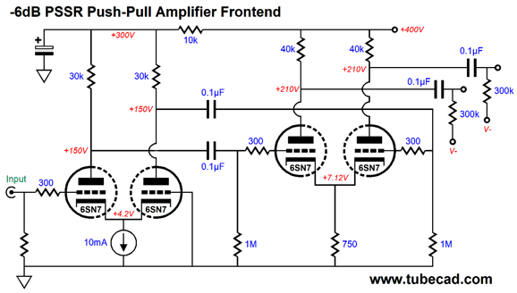
One workaround is to shunt the 43k plate resistor with a 49.9k resistor and 2.2µF capacitor in series. The gain drops to about ten (20dB) and 41.5% of the power-supply noise escapes out its output. The next stage is a split-load phase splitter based on a 12AX7 triode. (The idea here is that we could use a 12DW7/ECC832 dissimilar twin triode tube.)
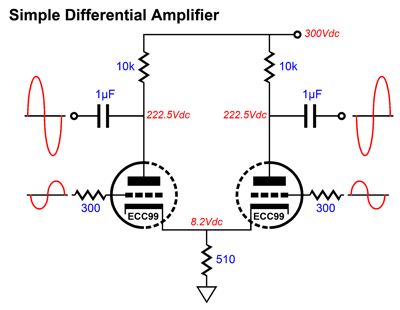
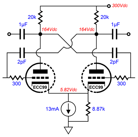
The thing interesting about this implementation is the large-valued (1µF) coupling capacitors, which are needed to ensure low phase shift at low frequencies. Both outputs leak, in phase, 41.2% of the power-supply noise. Obtaining perfect balance is key to making the second Aikido mojo trick work. The last stage is a differential amplifier based on an ECC99.
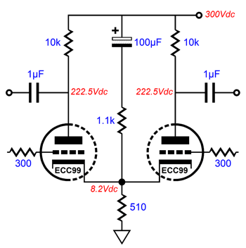
Not very interesting, I'll admit. Here is an interesting addition.
The addition of the 1.1k resistor and 100µF capacitor purposely injects a portion of the power-supply noise into the differential amplifier cathodes. Why? Since the split-load phase splitter leaks an equal (and in-phase) amount of power-supply noise, we can force a power-supply-noise null at the differential amplifier's outputs by injecting slightly less noise into the cathodes, as the noise at its grids will be slightly higher which will cause the differential amplifier to amplify the noise out of phase with the power-supply noise at the B+ voltage.
If we get the ratios right, the result will be a power-supply-noise null.
Since even this Aikido mojo trick didn't result in a deep power-supply-noise null, we should use an RC filter with a large-valued capacitor to first reduce the ripple before the Aikido mojo takes over. With an RC filter on the B+ voltage, the PSRR improves to -90dB at 100Hz.
Putting it all together is easy enough.
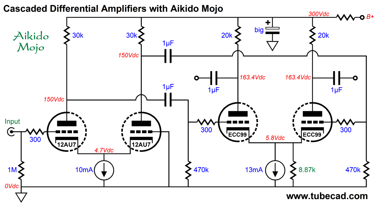
This differential-amplifier Aikido-mojo technique can also be used with a differential amplifier cascade.
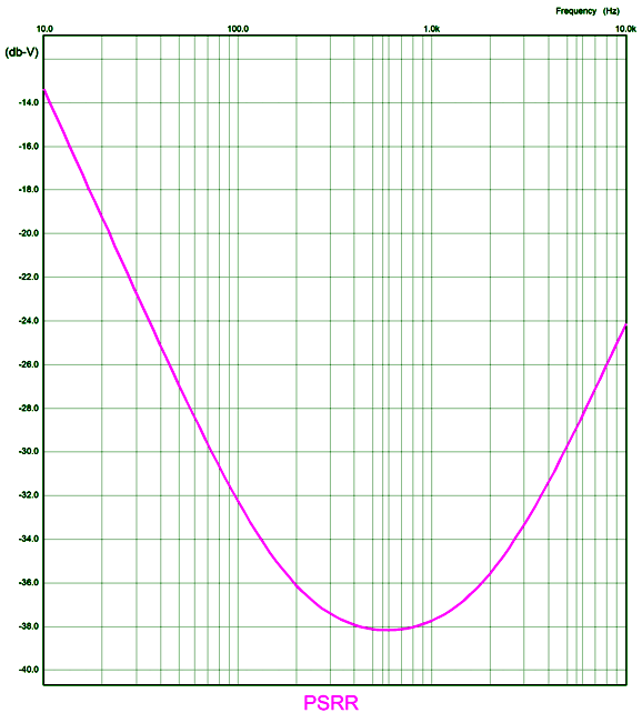
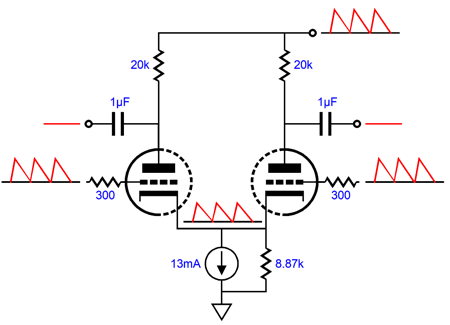
The input differential amplifier sees a constant-current source at its tied cathodes, so almost all of the power-supply noise will appear at the two plates. The reason that 100% of the noise does not leak out is that the 470k grid resistors define a two-resistor voltage divider with the 30k plate resistors. The added 71.5-ohm resistor and the second differential amplifier's 510-ohm shared cathode resistor also define a two-resistor voltage divider relative to the B+ voltage ripple. The resulting PSRR enhancement (-22dB) is great, as the two differential amplifiers in cascade would otherwise deliver power-supply noise gain, not attenuation. The downside to this noise-reduction technique is that it requires a large-valued capacitor to terminate the added resistor (71.5 ohms). What if both differential amplifiers get their own constant-current source cathode loading? In this configuration, we forgo the large-valued capacitor and low-valued resistor and place a shunting resistor across the constant-current source.
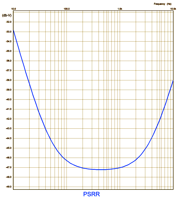
The total gain for this circuit with an unbalanced input signal is 1:130 (42dB), which should be enough to drive a tube-based, push-pull output stage, even with 300B output tubes. Negative feedback can be applied at the input stage's grounded grid. If the output tubes require only a quarter of the 1:130 gain, then the feedback ratio is 4:1 or 12dB. In theory, the shunting resistor would equal half the plate resistor value (i.e. in this example 10k), but as the triodes do not exhibit infinite transconductance and since the 470k grid resistors introduce some attenuation of the power-supply noise leaving the first differential amplifier, the optimal resistor value is closer to 8.87k.
The PSRR improves to a fine -46dB at 100Hz.
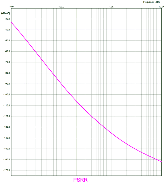
If we now use an RC filter with a large-valued capacitor to reduce the ripple prior to the Aikido mojo, we can achieve some stellar PSRR figures. A question often asked is, Which is better: a single RC filter with a large-valued capacitor and large-valued resistor or two RC filters in cascade, each holding half the values of the single RC filter?
The answer is that the two in series will yield greater power-supply noise reduction, but at the cost of twice the B+ voltage impedance. In this circuit, which draws a constant current, the increase in B+ voltage impedance makes no difference. On the other hand, in a circuit that experiences large unbalanced current swings, the higher impedance will become an issue. In other words, the true answer is it depends. There is still one trick we can add. The high-frequency bandwidth in SPICE simulations came in at 500kHz. We can more than double this -3dB frequency by cross-coupling two 2pF capacitors from plate to opposing grid, which will help neutralize the ECC99 triode's Miller-effect capacitance. Be careful, as too high a capacitor value will cause peaking and possibly oscillation.
Of course, we may not desire such high-frequency bandwidth. By the way, all these techniques assume that well-matched triodes are used and that tight-tolerance resistors are used. In other words, 10% resistors and twin-triode tubes with poorly matched triodes will not deliver stellar PSRR enhancements. If we seek the largest possible symmetrical output voltage swings from a differential amplifier with a constant-current source cathode loading and a given plate resistor value, the following formula comes in handy. Iccs = Vb/(Ra + rp) where Iccs is the constant-current source idle current; Vb, the B+ voltage; Ra, the plate resistor value; and rp, the triode's plate resistance.
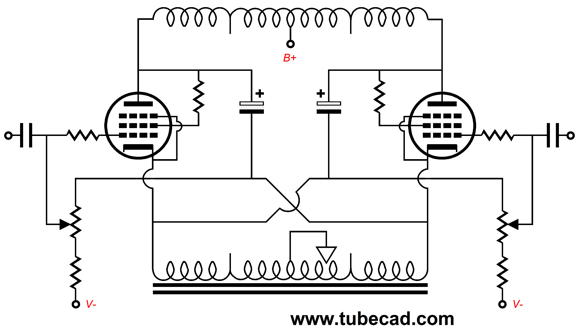
AnTec Output Transformers
In addition, they would work well in the circlotron variation that I have shown here many times before, the last time being in post 514, with output tubes; and with output MOSFETs in post 525. (If only to read the first paragraph, which is a doozy, post 317 is also worth reviewing.)
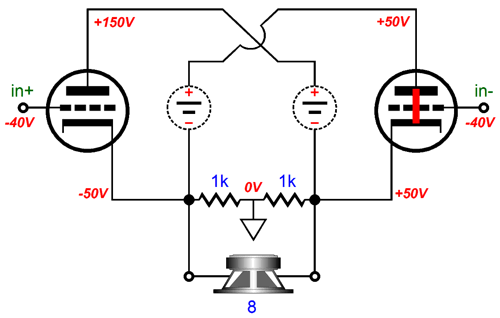
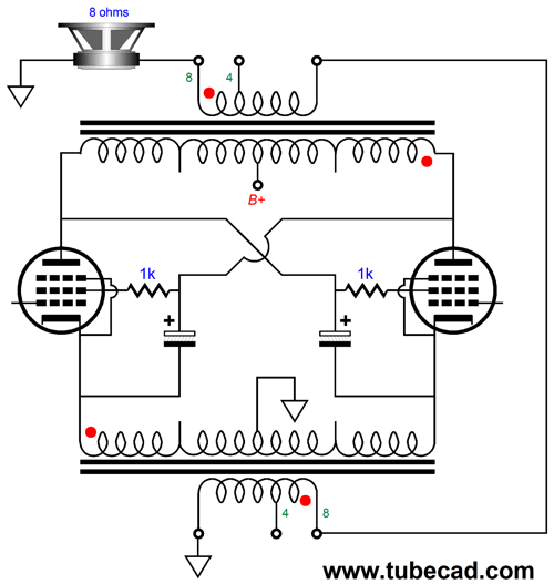
Normally, each channel of a circlotron amplifier holds two floating power supplies; not this variation. In fact, we could use one high-voltage power supply to power four channels of output. The secret is that the large-valued capacitors take the place of the floating power supplies. In terms of AC signal, the large-valued capacitors are effectively dead shorts; in terms of DC currents, they do not exist. The use of two output transformers per channel not only simplifies the power supply, it allows us to use better sounding output tubes, such as the 2A3, EL34, EL84, KT88, 300B… and many fewer of them. The DC-coupled OTL circlotron demands low-voltage, high-current tubes, such as the 6AS7 and 6C33, and many more of them, as an 8-ohm load is an insanely low impedance for any tube to drive directly. It takes eight 6AS7 twin-triode tubes to deliver 60W of output into an 8-ohm loudspeaker in the OTL circlotron, whereas a 60W transformer-coupled circlotron requires only two KT88 output tubes. In addition, transformer coupling is inherently safer. If an output tube arcs from cathode to plate, the output transformer might be damaged, but the speaker is safe. In an OTL power amplifier, the speaker will go up in smoke.
In contrast, the 100-volt DC differential voltage cannot be sustained across the secondary. If we use two 15W output transformers in this transformer-coupled circlotron, we can get 30W of output, as each output transformer will deliver half the output current, but the same output voltage as a single 30W output transformer would. What gets slightly confusing to many tube fanciers is that we must quarter the output transformer's primary impedance. In a conventional transformer-coupled, tube-based, push-pull power amplifier that runs in class-B or class-AB, the load each output tube sees at full output is one quarter the nominal plate-to-plate impedance. For example, a 4k primary impedance drops to 1k, once the other output tube cuts off. How is this possible? Once the output stage leaves its class-A window of operation, leaving only one output tube conducting, only half of the output transformer's primary is engaged. Thus, the winding ratio is halved, as the center-tap cuts the primary winding in half, which results in a quartering of the impedance ratio. An output transformer's impedance ratio is equal to its winding ratio squared.
For example, the AnTek MP-15W50 15W output transformer's winding ratio is 26:1 (aka its turns ratio), which squared equals 676:1; thus, an 8-ohm load is reflected to the primary as a 5408-ohm load, as 676 x 8 = 5408. But with its winding ratio halved, the impedance ratio becomes 13² to 1 or 169:1, so the 8-ohm load appears as a 1352-ohm load to the still conducting output tube. In the transformer-coupled circlotron, the winding ratio is never quartered; the load impedance remains constant even as the output stage leaves class-A operation, as the entire winding is always engaged. Not good, if the primary impedance is too high. Too high a primary impedance will require much larger plate-voltage swings to deliver the same amount of output power. For example, to get 30W with a 5408-ohm load requires peak voltage swings of 570Vpk, which would require a B+ voltage of about 700Vdc. Crazy high. With a 1352-ohm load impedance, however, we can get away with a B+ voltage of only 330Vdc and still deliver 30W. So, how do we quarter the impedance ratio of an existing output transformer? We use two output transformers and place their secondaries in series, which will effectively halve the winding ratio and quarter the impedance ratio.
One way to look at it is to see that effectively each secondary sees a 4-ohm load, and the two primaries are effectively in parallel, so the halved primary impedance gets halved again, leaving a quarter of the original 5408-ohm load impedance. What about 4-ohm loudspeakers? We must arrange the secondaries differently.
What about 2-ohm loads?
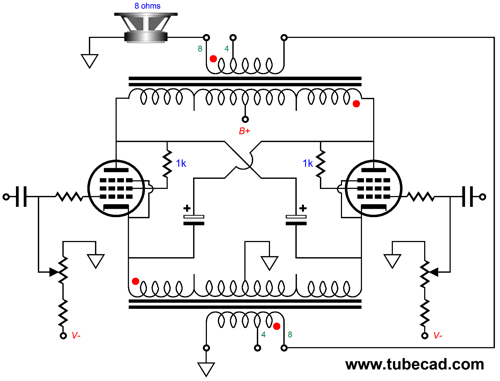
What about 16-ohm loads? Sorry, there is no arrangement that works with 16-ohm loudspeakers, as the secondaries would need 16-ohm output taps. Okay, it's time to pull back and ask ourselves why we should bother with this two-output-transformer circlotron rather than use a single 30W output transformer in a conventional push-pull power amplifier arrangement. The answer is that circlotron topology yields an effective gain of two and both a low output impedance and low distortion output, but without the cathode follower output stage's high input signal swings. In fact, it halves the needed input signal swings. This is a huge advantage, as it allows us to use the B+ voltage throughout, whereas the cathode follower output stage requires either inductive loading of the driver stage or a driver stage B+ voltage twice that of the output stage. In other words, it is much easier to provide ±160Vpk input signal to each output tube grid than it is to deliver ±320Vpk input signal. The price we pay, and we always must pay for what we get, is that the output impedance will be half that of a comparable cathode follower output stage. Was that a high price to pay? No. With two KT88 output tubes in the circlotron topology the cathode-to-cathode output impedance is about 100 ohms. We then divide this impedance by the output transformer's impedance ratio, which was 169:1 in this example; and we get 0.6 ohms, far lower than most tube-based amplifiers.
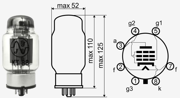
Since I mentioned the KT88, here is the KT88 configured as a pentode.
Note that this is true pentode operation, as the cathode-to-screen voltage remains constant. In SPICE simulations, this output stage delivered 30W with less than 1% distortion—without resorting to a global negative feedback loop! This is a huge advantage. Of course, the input and driver stages must add their distortion to the mix. Speaking of those stages, we should use a driver stage with a PSRR of -6dB, as the KT88 cathodes are bouncing at half the B+ voltage ripple, so their grids should also see 50% of the power-supply noise. The following example is from post 514.
The RC capacitor must be huge, as the input stage differential amplifier offers no power-supply rejection, the result of the constant-current source loading of the tied cathodes. The driver stage differential amplifier must see a shared cathode resistor, not a constant-current source. (No doubt, some reader will build this circuit and replace the shared cathode resistor with a constant-current source, and then complain that the PSRR is zero.) If we are willing to give up on some potential output power, which many audiophiles are not willing to do (and probably for the same reason that penis-reduction operations are so rare), we could run the KT88 output tubes in triode-mode, which reduces the output power to about 20W, but 20W at much lower distortion; in addition, the output impedance falls to about 90 ohms on the primaries. But in order to get this power from the triode-connected KT88 output tubes, we must both reduce the idle current and up the B+ voltage.
Note that we should add the garter-belt arrangement of the fixed bias potentiometers.
This arrangement wonderfully self-balances, as both output tubes strive to eliminate a DC offset across the primaries. The triode-connected arrangement is what I would use, as the loss of 10W is little compared to the improvement wrought by triode operation. What about ultra-linear operation? We could set it up, but it would mean that we would have to use two more large-valued capacitors per channel. Possibly, we would get more power than pentode operation with less distortion and output impedance. See post 514 to see how ultra-linear operation is set up. Since the AnTek MP-15W50 15W output transformers are so reasonably priced, wild experimentation would not prove all that expensive. Ideally, AnTek would make an output transformer that held two center-tapped primaries and one secondary just for this circlotron use. The winding ratio would start low, say, 13:1, so there would be no need to fiddle with two secondaries.
In addition, since the winding ratio is halved, the fidelity should improve. Such an output transformer rated for 50W to 60W would prove ideal for many. I can imagine, however, that many would prefer an output transformer rated for 100W or 200W. As the output power goes up, the winding ratio should go down, as many more output tubes must be used in parallel. As an interesting math problem, how much output wattage would be needed to get to a winding ratio of 1:1? Let's assume that 6AS7 output tubes are used, which present a nominal plate resistance of 280 ohms. Hint: the 6AS7 will pass 200mA with a cathode-to-plate voltage of 50V and cathode-to-grid voltage of 0V and its plate resistance will be 230 ohms at that operating point. Since the winding ratio is unity, we do not really need a secondary, so only two windings are needed.
If we are willing to drive the 6AS7s into positive-grid current, we can get a lot more current flow. For example, a 6AS7 will draw 0.8A with a cathode-to-plate voltage of 11V and cathode-to-grid voltage of +40V and its plate resistance will be 194 ohms at that operating point. Mind you, huge driver output voltages are needed. Okay, some oppose the very idea of departing from the standard transformer-coupled tube power amplifier. Well, we could still take advantage of the better bandwidth provided by the AnTek MP-15W50 15W output transformers by placing several of them in parallel to get much higher output wattage. The only problem we might face is that the primary impedance will prove too high.
Four 15W output transformers in parallel will put out 60W. To use a 4-ohm speaker requires a different arrangement.
Both arrangements shown above results in 2700-ohm primary impedance, which allows the four KT88 output tubes to deliver the 60W of power. Why not just use a 60W output transformer? We could, but here is what we must deal with:
This is the frequency response of the MP-60W66, AnTek's 60W transformer. The issue is not just that the highs fall off, but that it gets squiggly at 30kHz, which will make applying negative feedback. Now, let's compare this graph to the one for the 15W transformer.
Which do you prefer? By the way, I understand that one of the most expensive and highly-esteemed tube power amplifiers sports potted output transformers, which contain many small flat pancake output transformers wired in parallel. What you do not see, you do not worry about.
Music Recommendation: Domador De Huellas
//JRB
Did you get your money's worth with this post by me? If so, think about supporting me at Patreon.
User Guides for GlassWare Software
For those of you who still have old computers running Windows XP (32-bit) or any other Windows 32-bit OS, I have setup the download availability of my old old standards: Tube CAD, SE Amp CAD, and Audio Gadgets. The downloads are at the GlassWare-Yahoo store and the price is only $9.95 for each program. http://glass-ware.stores.yahoo.net/adsoffromgla.html So many have asked that I had to do it. WARNING: THESE THREE PROGRAMS WILL NOT RUN UNDER VISTA 64-Bit or WINDOWS 7, 8, and 10 if the OS is not 32-bit or if it is a 64-bit OS. I do plan on remaking all of these programs into 64-bit versions, but it will be a huge ordeal, as programming requires vast chunks of noise-free time, something very rare with children running about. Ideally, I would love to come out with versions that run on iPads and Android-OS tablets.
|
I know that some readers wish to avoid Patreon, so here is a PayPal button instead. Thanks. John Broskie
John Gives
Special Thanks to the Special 86 To all my patrons, all 87 of them, thank you all again. I want to especially thank
I am truly stunned and appreciative of their support. In addition I want to thank the following patrons:
All of your support makes a big difference. I would love to arrive at the point where creating my posts was my top priority of the day, not something that I have to steal time from other obligations to do. The more support I get, the higher up these posts move up in deserving attention.
If you have been reading my posts, you know that my lifetime goal is reaching post number one thousand. I have 471 more to go. My second goal was to gather 1,000 patrons. Well, that no longer seems possible to me, so I will shoot for a mighty 100 instead. Thus, I have 13 patrons to go. Help me get there.
Support the Tube CAD Journal & get an extremely powerful push-pull tube-amplifier simulator for TCJ Push-Pull Calculator
TCJ PPC Version 2 Improvements Rebuilt simulation engine *User definable
Download or CD ROM For more information, please visit our Web site : To purchase, please visit our Yahoo Store: |
|||

.png)


| www.tubecad.com Copyright © 1999-2021 GlassWare All Rights Reserved |