| John Broskie's Guide to Tube Circuit Analysis & Design |
07 July2021 Post 539
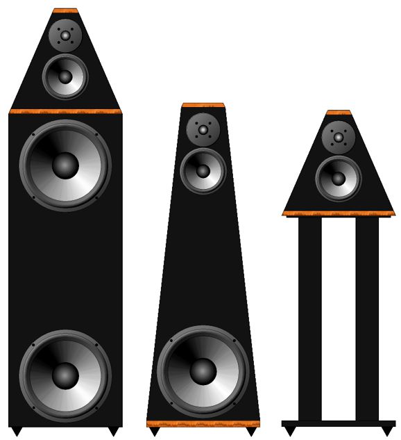
Loudspeakers Here is a philosophical question for you: if you heard a perfect loudspeaker, would you recognize it as being perfect? Perhaps not. Why wouldn't a perfect loudspeaker please us? Perhaps you would find it lacking bass punch and sizzling highs, sounding a bit too polite, too bland. We are used to Hi-Fi sound, just as we are used to women filled with silicone, adorned with artificial eyelashes, tattoos, and dramaturgically bulbous and pouting lips. Absent the Hi-Fi affectations and exaggerations, perfection may not make the grade. At the 2012 RMAF, I was startled to hear the Acoustic Zen Crescendo loudspeakers. From post 247:
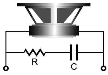
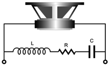
Speaking philosophically, the question I have presented to ardent cable fanciers many times before is: Which would sound better, $200 loudspeakers with $20,000 speaker cables or $20,000 loudspeakers with $200 cables? (The weasel answer I once got was $20,000 speaker cables with $20,000 loudspeakers.) In short, few would deny that loudspeakers need more development. We can improve either the speaker drivers (very hard) or the cabinets (hard, but doable) or the electrical portions, such as crossovers and Zobel networks (not so hard physically, but hard mentally). I am not talking about $3,000 crossover-capacitor upgrades, but topological improvements. (Which would sound better, a $100 loudspeaker with a $900 passive crossover or $900 loudspeaker with a $100 passive crossover? In both cases, the total cost is $1,000.) The topic of crossovers gets complicated quickly, as I discovered recently while trying to sort and catalog crossover topologies. Not easy. For example, a crossover that fails when driven by a voltage-out power amplifier succeeds when driven by a current-out amplifier—and vice versa. In contrast, the lowly Zobel network is a simple affair, holding only two components: one resistor, one capacitor. For a passive loudspeaker crossover to work well, its terminating load impedance should resemble a resistor. Sadly, speaker-driver impedance plots most often resemble ragged mountain ranges than ruler-flat lines. The average 8-ohm woofer's impedance plot may only intercept 8 ohms at two frequencies. The problems are its resonant frequency (Fs), which produces a high peak in impedance, and its own internal inductance (Le) due to the round voicecoil surrounding an iron magnet assembly. Mechanically, loading a woofer with a resistive transmission-line enclosure can damp the resonant impedance peak. Electrically, placing a Zobel network of a resistor in series with a capacitor across the woofer's terminals can null the driver's "Le" inductance. The math is simple enough: the resistor value equals the nominal speaker impedance (R), usually 8 ohms; the capacitor equals
where the result is in µF.
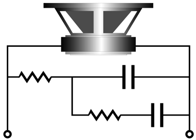
When we actually put such a Zobel network in place and measure the driver's impedance plot, we see a certain improvement, as the rising impedance with rising frequencies is flattened, but not completely. First of all, why doesn't the Zobel resistor value equal the driver's Re DC resistance? Indeed, why does a nominally 8-ohm woofer present a DC resistance of only 5.5 to 7 ohms? More details are needed, as a woofer's cone moves it introduces all the issues of mechanical and air resistances and surround and spider compliances. I remembered seeing a more complete Zobel version online. I found it again at the audioexpress website.
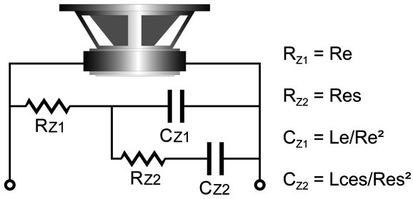
The article was taken from www.cjs-labs.com and, as we can see from the comments at the bottom of the audioexpress webpage, the article fails to provide sufficient information for us to make the improve network. For example, it fails to explain what the variables L2 and R2 are, stating only, "The component values are easily found if the L2/R2 impedance model values are known." Great, but what if they are not known? It took a little head scratching, but I finally determined that R2 was a driver's Res, which we can find with the following formulas Res = Bl²/Rms = Re × Qms/Qes The variable Rms is the sum of the mechanical losses, which few data sheets provide. At the very least, however, variables Re, Qms, and Qes can be found in the driver's specification sheet, as most speaker makers now list all the Thiele-Small parameters (aka TSP). Decades ago, I had to distill the needed TSP values from actual woofer testing and applying the mathematical analysis; today, we can buy for only $129 a computer-based speaker test system that does all the hard work for us. In addition, I concluded that the improved Zobel network's L2 inductance is the driver's Lces mechanical inductance, which we can find with the following formulas Lces = Bl²/Cms = Re×1000/(2¶FsQes) with the result in milliHenries
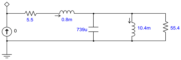
The variable Cms is the sum of the drivers' surround and spider compliances; Qes, the driver's electrical Q. I decided to try out this improved Zobel network in SPICE simulations. First, I had to find an existing SPICE electrical model of some woofer that held all the needed values.
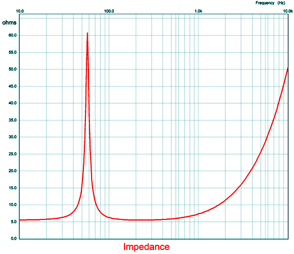
where 5.5 ohms is the speaker's Re resistance; 0.8mH, the Le inductance; 55.4 ohms, the Res resistance; 10.4mH, the Lces inductance. Next, I ran simulations to plot the impedance against frequency graph.
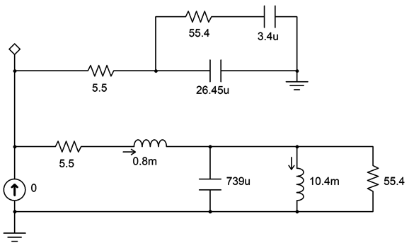
(The key is to measure absolute magnitude of developing voltage, not its real or imaginary value in SPICE.) It sure looks like a woofer impedance plotline. Adding the improved Zobel network looks like the following.
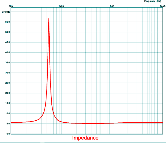
The resulting SPICE-generated impedance graph shows a nice flattening at higher frequencies.
Not bad. Note that impedance now matches the Re resistance. Mind you, this assumes a woofer mounted on an open baffle (i.e. a dipole) enclosure, not a sealed box or a ported cabinet. For a woofer in an acoustic-suspension enclosure (i.e. a sealed box), the following formulas are needed. Res = Re×Qmc/Qec and Lces = Re×1000/(2¶FcQem), which are the Qs and the resonant frequency in the cabinet. So, are we done? No. Even this improved Zobel network may not result in a flat impedance (at least at high frequencies). Why not? Some woofers include copper shorting rings to reduce their inductance. In addition, the equivalent electrical models fail to include eddy currents in the speaker's iron motor structure, which no one has successfully modeled as far as I know. Still, this is a move in the right direction.
Crossover Thoughts
The theoretically best crossover, the 1st-order two-way, is also the worst practical crossover, as it offers too little protection to the tweeter and assumes super-wide bandwidth from both woofer and tweeter. (This is where two fullrange drivers would shine, as we could use a low crossover frequency, say 600Hz, and still get great performance; since both drivers would offer the exact same bandwidth and phase characteristics and the distance between driver centers would be small relative to the crossover frequency wavelength, blending would be near perfect.)
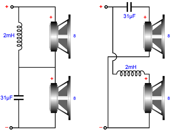
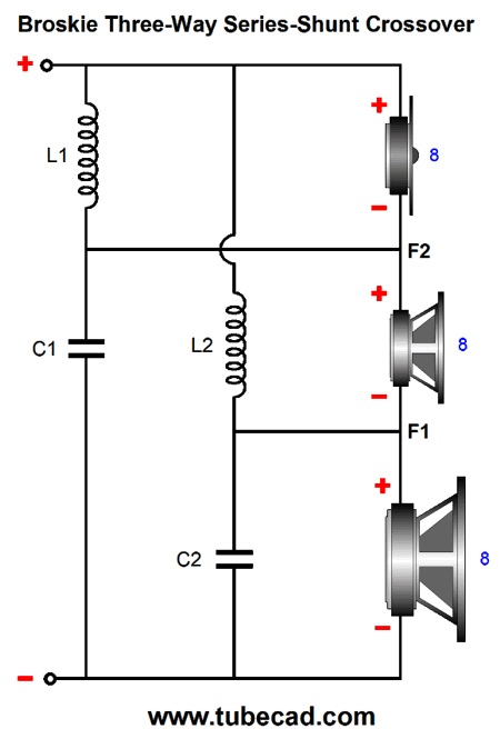
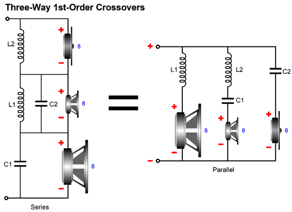
After I posted in 2019 post 473 , a reader wrote to me, explaining that he had rewired his existing three-way parallel 1st-order crossover to the series-shunt configuration and preferred the resulting sound. But as he feared the non-flat impedance interacting with his single-ended power amplifier, he returned the crossover to its original configuration. Makes perfect sense, right? No.
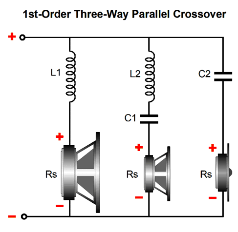
Here is why: the three-way parallel 1st-order crossover also presents a non-flat impedance, with the same dip in impedance in the center frequency. In fact, this parallel crossover is worse in that it does not deliver a flat frequency response with a voltage-out power amplifier, but it does with a current-out amplifier, in spite of the non-flat impedance. In contrast, the series-shunt fails with a current-out amplifier and succeeds with a voltage-out amplifier. What makes this situation even more complicated is that most single-ended power amplifier's offer a very poor damping factor; in other words, their output impedance is often high, say from 1 ohm to 4 ohms. With a 3-ohm output impedance, it might be a toss-up as to which crossover works best, although I would still bet on the series-shunt proving the better crossover, due its progressively steeper slopes for the woofer and tweeter.
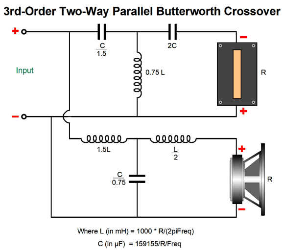
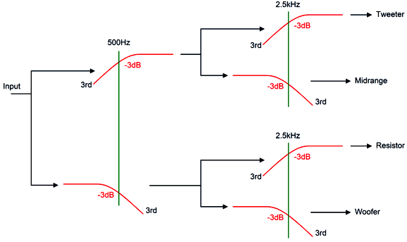
Recently, I have been thinking about 3rd-order crossovers, as they provide great protection for the delicate tweeter and allow for lower crossover frequencies. I have heard many fine-sounding two-way loudspeakers with 3rd-order crossovers, but few three-way speakers. Puzzling. SPICE simulations reveal a lumpy frequency response with three-way 3rd-order parallel crossovers. (A three-way 3rd-order series is likely impossible to build.) One thought I had was that if we cascade the tweeter's filter so that the tweeter sees an 18dB slope at its crossover frequency and then a 36dB slope below the midrange crossover frequency, we could get a much flatter frequency response—at least between the midrange and the tweeter. Indeed, that is what SPICE simulations revealed. Still troubled by the tumble at the crossover between woofer and midrange, I wondered if I could force a second crossover filter on the woofer at the tweeter crossover frequency. I could. This is the conceptual layout. (Always start at the highest level of abstraction you can, then move down to more details.) The woofer is effectively working with its own imaginary tweeter, which give the 3rd-order low-pass filter a better load impedance to work into. In addition, the woofer sees a secondary 3rd-order low-pass filter at the tweeter crossover frequency.
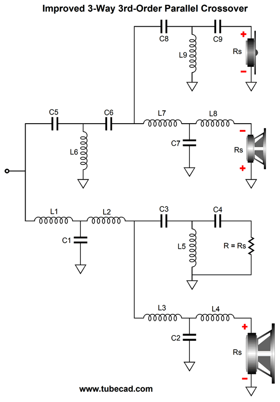
The result is a crossover that works equally well with current-out and voltage-out power amplifiers and offers an extremely flat frequency response.
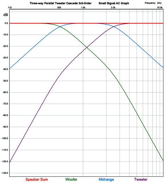
Note the amazing attenuation of the tweeter at low frequencies. The impedance plot is equally flat.
Note the Y-axis with its 0.1-ohm divisions. This crossover, however, is not phase flat. In fact, from 20Hz to 20kHz, the output undergoes a -360 degree phase shift. Yet, SPICE simulations showed that tone-bursts didn't provoke usual garbled output that other crossover design have produced.
The tone-bust consisted of two cycles of 1kHz. Bear in mind that tone-bursts are the hardest (and most like music) tests a speaker can undergo. In contrast, steady sine waves are a breeze and least like music. Apply a similar tone-burst to the famous K-horn and you will see three sinewave bursts, as the tweeter's arrives first, then the midrange, and finally the woofers, much later. Yet, the steady-sinewave test could show a flat frequency response. Are the results worth the needed addition of three extra capacitors and three inductors? I believe so, as the added high-pass filter can use cheaper parts since only a dummy resistor is being driven; moreover, the progressively steeper crossover slope for the woofer can only help.
Three-Way Crossover Woes
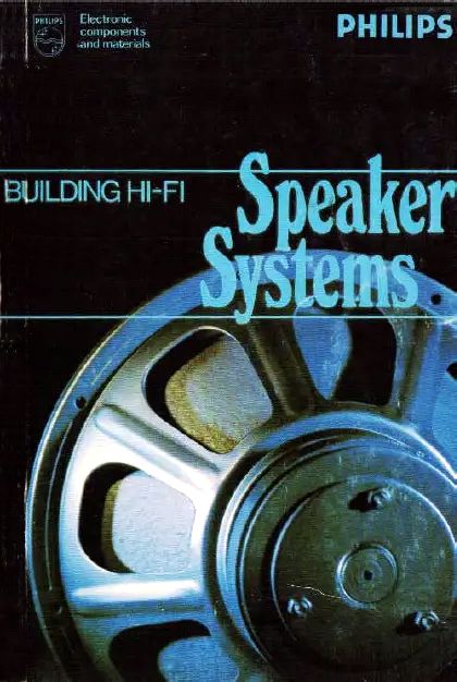
The textbook workaround is to skew the three filter frequencies so a compromise is achieved. I first saw this approach for parallel crossover detailed in a book on loudspeakers by the Dutch Philips speaker division (Gloeilampenfabrieken), Building Hi-Fi Speaker Systems, written in 1977 (6th edition, complete revision).
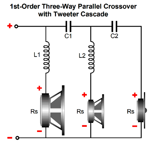
The original two target crossover frequencies are replaced by five frequencies, four crossover frequencies and the geometric-mean frequency. Does it work? No. It still fails to deliver the flat impedance and frequency response we desire. Back in the 1980s and 1990s, several attempts were made to provide a better solution, but with limited success. In contrast, cascading filters CAN deliver a flat impedance and a flat frequency response. Here is a 1st-order parallel example.
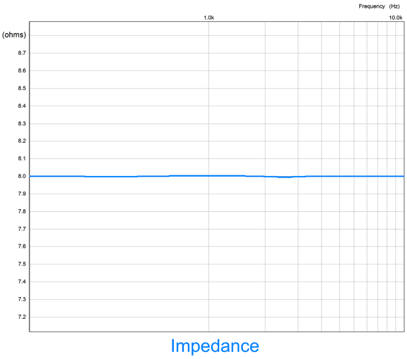
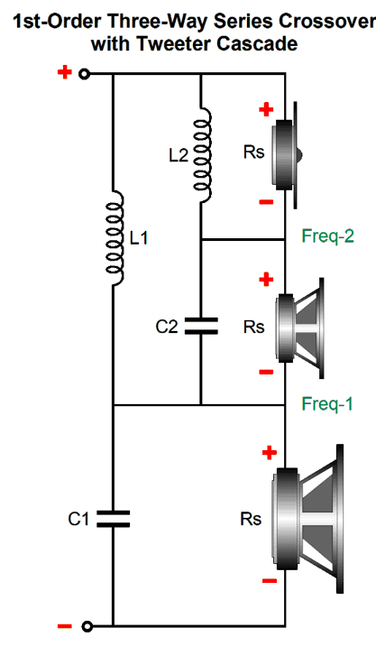
In the non-cascaded version, the impedance drops from 8 ohms to 6 ohms at the center frequency (1.1kHz) and the output peaks at +2.5dB at this frequency. In contrast, this version presents a ruler flat impedance and frequency response, with the added bonus of greater protection for the tweeter. We can cascade a 1st-order series three-way crossover just as easily.
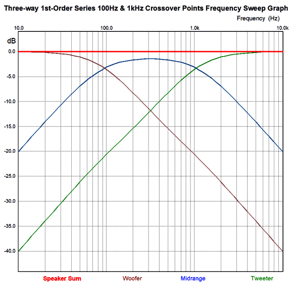
The same flat plot result. Well, how flat is the 3rd-order parallel and series three-way crossover with the tweeter cascade? This flat:
Of course, actual drivers will muddy the results with their deviations from ruler flat output, but at least this crossover topology offers the possibility of flat impedance and frequency response.
By the way, a friend told me that the loudspeakers he recently bought differed from the more conventional speaker in that the designer/builder didn't use the same-valued crossover parts in all his speakers, as he hand-selected capacitor and inductor values to match each particular speaker driver. Is this a good idea? No. I came up with a fine analogy—well, at least I deemed it so. Imagine you buy a used car. All four tires of the car are different diameters and widths, but the seller has under- and over-inflated each tire to the right amount so the parked car is parallel to the road. A perfect solution? No, as driving the car around the block would soon reveal. A static uniformity does not necessarily produce a dynamic uniformity. (I repeatedly tell my 18-year-old son that he is too young to make productive analogies. He asked how old one needed to be to make a good analogy. My answer was seldom before the age of 30.) The ideal situation is perfectly matched drivers and perfectly matched crossovers between left and right speakers. Why don't speaker builders use cascading crossovers? My guess is that few know that they are possible and the few who do know fear that the drivers will play too great a role in the crossover functioning, as speaker drivers are not resistors. In other words, they fear that the midrange's own resonant frequency and intrinsic inductance will twist the cascading crossover's output to the tweeter. And they like the idea of each driver getting its own separate, discrete, isolated crossover filter, as they imagine that each separate crossover filter would prove easier to tweak for its driver. Much like the seller of the used car with four different sized tires imagining that beyond varying the air pressure in each tire separately he only needs to adjust each shock absorber and suspension coil then the car would drive truly flat. In addition, they might fear that placing more capacitors in the signal path will rob the tweeter of extended shimmer; indeed, they might fear the expense of having to use two high-quality crossover capacitors, rather just one for the tweeter. And there's the issue of using dissimilar driver impedances, say a 4-ohm woofer with an 8-ohm tweeter. Of course, my view entirely differs. The cascading crossover offers far too many benefits to ignore, such as the ability to be driven equally with either voltage-out or current-out or high-output impedance amplifiers and both a flat impedance and frequency response—along with the huge advantage of greater protection for the tweeter due to the resulting two-slope low-frequency cutoff. A 2nd-order series cascading three-way crossover offers a good solution to the three-way crossover problem. We must use the Linkwitz-Riley 2nd-order alignment along with my impedance-flattening network.
In spite of the complicated arrangement, the math is simple
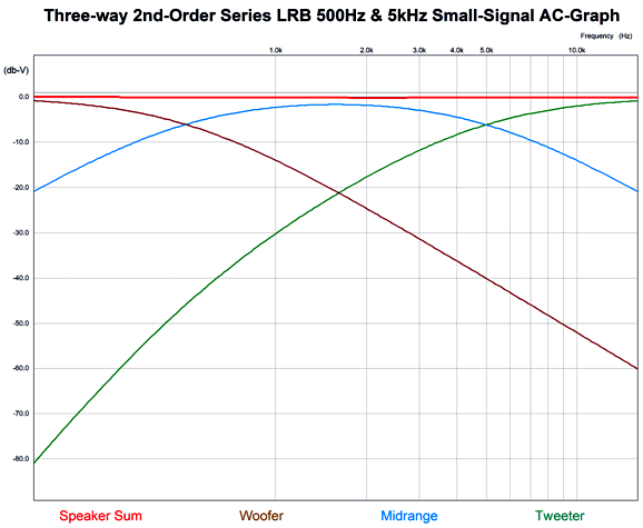
The result is a flat impedance and frequency response (actually, there is a -0.135dB dip at the center frequency, which can be compensated by using a midrange with a +0.135dB greater SPL). The further apart the two crossover frequencies are the better. Like all non-1st-order crossovers, the output is not phase flat. On the other hand, the tweeter sees far less low-frequency output, making the loudspeaker far more robust. With crossover frequencies of 500Hz and 5kHz, the tweeter's output at 100Hz is down 96dB, which is only 0.00158%. Assuming an 8-ohm loudspeaker, with 100W of white noise signal, the tweeter would see 0.6mV of signal at 100Hz.
An added feature of the series LR arrangement is that the capacitor values are halved compared to the parallel arrangement. Moreover, the woofer and midrange Le inductance is no longer a liability, as they can be subtracted from their series inductor's value. The tweeter should be shunted with a Zobel network and, possibly, a series-notch filter to null the impedance peak at its resonant frequency. Hold on, John, what is a series-notch filter? A series-notch filter consists of an inductor in series with a resistor and a capacitor that shunts a driver's voicecoil and is tuned to the driver's resonant frequency. The math is simple enough.
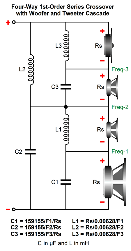
Where the inductor is in milliHenries and the capacitor is in µFs. Usually, we only see series-notch filters on the midrange and tweeter, as most woofer require huge inductor and capacitor values, especially the latter. What about four-way crossovers. I would use a 1st-order series with woofer and tweeter cascade.
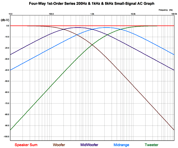
This crossover offers a flat impedance, frequency response, and phase response; and works equally well with voltage-output and current-out power amplifiers. I would use identical drivers for the woofer-midrange and midrange. Possible crossover frequencies would be 200Hz, 1kHz, and 5kHz. Note how the midrange covers entirely the critical range between 3kHz to 3.5kHz, where the inner ear resonance occurs and where the ear is most sensitive to phase aberrations.
Note how the tweeter is down -60dB at 100Hz, which means that 1/1,000th of the signal the woofer sees is making it to the tweeter. In many ways, the midrange-woofer performs the major role, as it covers the frequency range most filled with musical signal; its slopes are 1st-order throughout. The midrange slopes are also a constant 1st-order 20dB per octave. The tweeter starts at 1st-order, then moves on to 2nd-order, and ends at 3rd-order 60dB per octave. The downside to the crossover is that we cannot bi-wire and that all three crossover capacitors should be of the highest quality (within reason and the constraints of your wallet, of course). See post 403 for information on how to bypass more than one capacitor at a time. Okay, I have to admit that I bring an odd perspective to the topic of loudspeaker and crossovers: a wimpy-tube perspective. I like triodes and single-ended power amplifiers, which means that 30W seems like gobs of power to me. Not everyone shares this perspective. Indeed, in world of 500W class-D amplifiers, I belong to a tiny minority. Most have never heard a tube-based power amplifier; and of the few who have, few have heard a triode-based single-ended power amplifier. In other words, a minority within a minority. This perspective inclines me to worry far less about blowing up tweeters or midranges. Moreover, in spite of what my wife says, I listen to music at far lower SPL than most audiophiles, nor do I listen to machine-gun fire, explosions, grunge, nu-metal, or pounding rap.
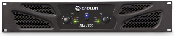
For less than the cost of a single NOS power tube, we can spend $365 on a Crown XLi 1500 power amplifier that puts out 900W in bridge mode. (They also make a 2700W bridge-mode version.) My single-ended power amplifier puts out 100 times less power, i.e. 9W. I do not worry about blown tweeters. Owners of Crown XLi 1500 power amplifiers do. We can protect a tweeter connected to a 900W power amplifier either by never turning the amplifier on or by placing two shunting zeners across the tweeter or by using a higher crossover frequency and/or using a steeper crossover slope. A four-way, 2nd-order crossover with a tweeter cascade with a tweeter crossover frequency of 5kHz results in the 100Hz signal being -114dB down relative to the woofer, which means that the tweeter sees a 100Hz signal 0.000002 times as big as the woofer sees. The question remaining to be answered is, Can we actually make a four-way, 2nd-order crossover with a tweeter cascade crossover that deliver a flat impedance and frequency response? We can. Fasten your mental seatbelts. Nine capacitors, nine inductors, and three resistors are required, but only three capacitor values and three inductor values and one resistor value need to be calculated. The paucity of part values is a huge advantage. As it makes shopping for crossover parts much easier and allows us to qualify for the ten-item price discount. (Get five of your friends to build loudspeaker with you, and all of you can enjoy hundred-item discounts. If the math seems wrong, you forgot to factor in stereo loudspeakers.) The crossover yields a dang close to flat frequency response in SPICE simulations, being only 0.46dB shy at the half the tweeter crossover frequency, which we can bring up to ±0.1dB by using a mid-woofer that is 0.34dB and a midrange that is 0.75dB louder than the rest of the drivers. Mind you, 0.34dB is an insanely small difference when dealing with drivers that are seldom within ±3dB across their pass-band. Here is the math for the crossover values.
Note that capacitor and inductor values are what would be used in a 1st-order crossover. Also note that inductors L1, L4, and L7 can be smaller in value than specified, as we can include the woofer's, the mid-woofer's, and the midrange's own Le inductance in the sums. (Inductances, like resistances, add together when in series.) What about a five-way version? We could, but I wouldn't. For those daring types, all that is needed is to add another Linkwitz-Riley series 2nd-order crossover with its own Broskie impedance-flattening network. Indeed, we could keep adding cascades of two-way filters. Imagine a loudspeaker whose many drivers each covered only one octave. Who knows, it might even sound good.
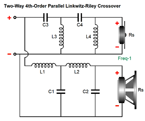
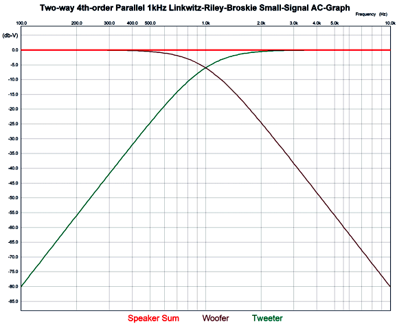
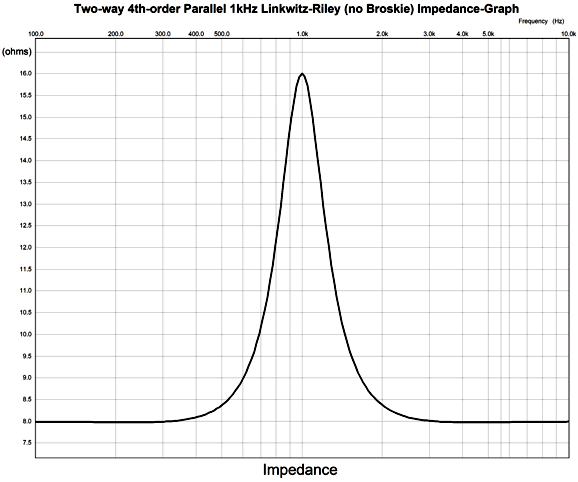
4th-Order Linkwitz-Riley Plus Broskie The 4th-Order Linkwitz-Riley alignment delivers a -6dB attenuation at the crossover frequency for both woofer and tweeter, much like the 2nd-order version, but yields slopes twice as steep, i.e. 80dB per decade, 24dB per octave. Like the 2nd-order version, the 4th-oder is not impedance flat, exhibiting a peak twice the nominal driver impedance at the crossover frequency. For example, with 8-ohm drivers and a crossover frequency of 1kHz, the impedance will be 16 ohms at 1kHz, falling back down to 8 ohms at 100Hz and 10kHz. This is not a problem for most solid-state power amplifiers, as 99.9999% of them are voltage-output amplifiers. It is a huge problem with current-output amplifiers and can be, however, a small-to-big problem with high-output impedance tube-based power amplifiers. The workaround is to add an impedance flattening network across the crossover.
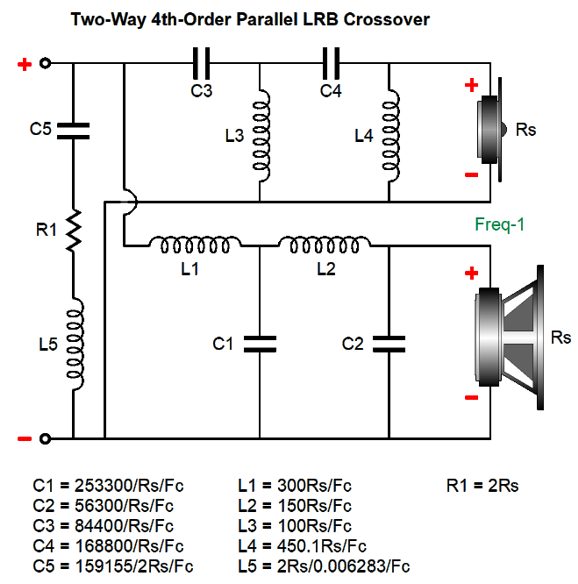
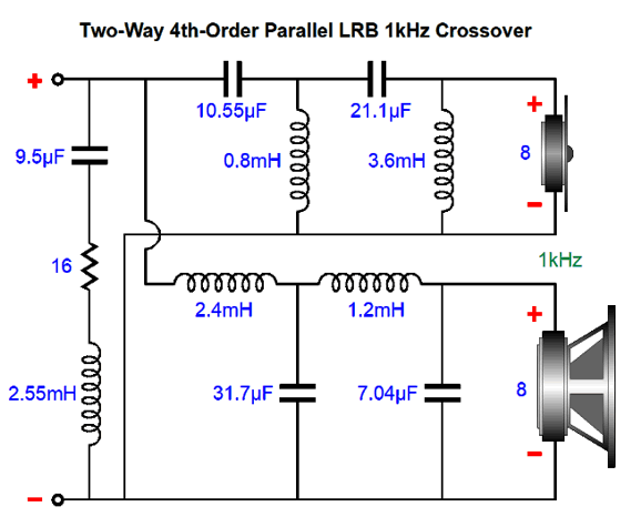
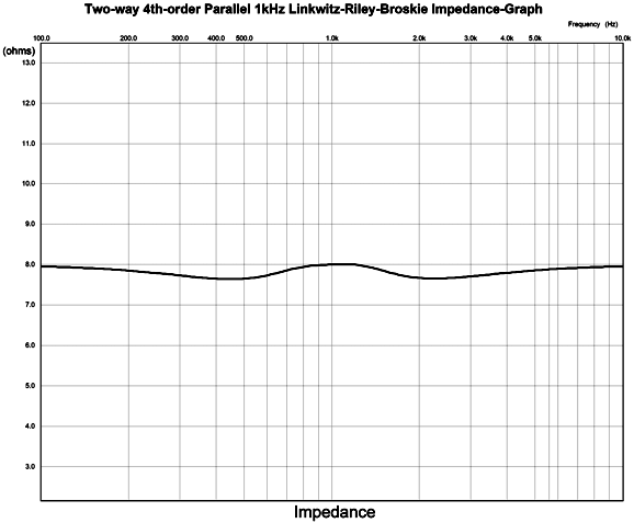
The resistor fully engages at the crossover frequency, bringing the impedance down to flat. The resistor must be twice that of the drivers; for example, 16 ohms with 8-ohm drivers. What if the woofer is a 4-ohm type, while the tweeter is 8 ohms? No go. With dissimilar driver impedances the loudspeaker impedance was never going to be flat anyway. Here is the needed math for making an impedance-flat 4th-Order Linkwitz-Riley crossover. Note that the impedance-flattening network capacitor and inductor values do not match the 2nd-order version's values, due to the 4th-order alignment. Here is an example crossover with a crossover frequency of 1kHz, which would work well with a midrange-tweeter horn. Now, we see the frequency plots. And the impedance plotline
Not perfectly flat, but compare it to no impedance-flattening network.
Starting from 300Hz to 3kHz the impedance departs from flat.
Music Recommendation: Nduduzo Makhathini's Amazon Music Service offers it 24-bit, 48kHz, if my memory is correct. //JRB
Very few can imagine just how much hard work is required to make one of my posts. If you have any sort of inkling or intuition of what is involved, please think about supporting me at Patreon.
User Guides for GlassWare Software
For those of you who still have old computers running Windows XP (32-bit) or any other Windows 32-bit OS, I have setup the download availability of my old old standards: Tube CAD, SE Amp CAD, and Audio Gadgets. The downloads are at the GlassWare-Yahoo store and the price is only $9.95 for each program. http://glass-ware.stores.yahoo.net/adsoffromgla.html So many have asked that I had to do it. WARNING: THESE THREE PROGRAMS WILL NOT RUN UNDER VISTA 64-Bit or WINDOWS 7 & 8 & 10 or any other 64-bit OS. I do plan on remaking all of these programs into 64-bit versions, but it will be a huge ordeal, as programming requires vast chunks of noise-free time, something very rare with children running about. Ideally, I would love to come out with versions that run on iPads and Android-OS tablets.
//JRB |
|
I know that some readers wish to avoid Patreon, so here is a PayPal button instead. Thanks. John Broskie
John Gives
Special Thanks to the Special 81 To all my patrons, all 81 of them, thank you all again. I want to especially thank
I am truly stunned and appreciative of their support. In addition I want to thank the following patrons:
All of your support makes a big difference. I would love to arrive at the point where creating my posts was my top priority of the day, not something that I have to steal time from other obligations to do. The more support I get, the higher up these posts move up in deserving attention.
Only $12.95 TCJ My-Stock DB
Version 2 Improvements *User definable Download for www.glass-ware.com |
||


| www.tubecad.com Copyright © 1999-2021 GlassWare All Rights Reserved |