| John Broskie's Guide to Tube Circuit Analysis & Design |
31 July 2022 Post Number 562
DC-Block Kit (By the way, some are arguing that we should ditch AC wall voltage for DC instead, as solar cells put out DC, not AC; and most of the devices in your home must convert the AC into DC before using a switching power supply to bring the DC down to a usable voltage such as 5Vdc. Sorry, George Westinghouse, but Edison might win after all—in spite of your being right.)
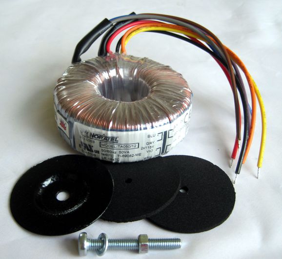
In contrast, the old-fashion tube power transformers contain so much slop in their construction of I and E plates that an implicit air-gap is created, which allows the transformer to sustain the DC offset without saturating.
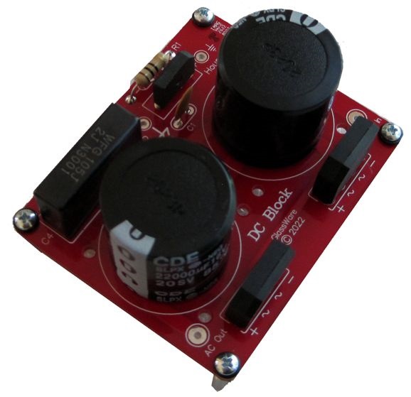
I am convinced that some DC saturation explains that odd situation wherein a modern power amplifier sounds fabulous at one house, but not at another. (The same is true of phono preamps and RFI ingress. I remember hearing lovely LP playback in the solitary house atop rolling hills overlooking fields of crops, but being hearing itchy sound from the same preamp in an apartment in San Francisco, whose outer wall hid from sight the huge neon sign on the other side.) The workaround is to either move or block the DC from entering the power transformer. Really, what is needed is a huge, high-voltage coupling capacitor, which is simply impractical, as 10,000µF/400V film capacitors might be made, but they would be bigger than a garbage can and cost a fortune. The workaround is to use two high-valued but low-voltage electrolytic capacitors in series with safety voltage clamps that prevent over voltages.
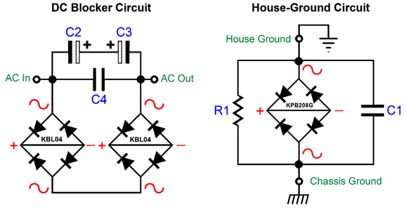
Two rectifier bridges are used to double the maximum amount of DC that can be blocked to four rectifier voltage drops, about 2.8V. The two 22kµF/16V capacitors are in series, which effectively creates a non-polarized electrolytic capacitor and are shunted by a 1µF/630V polypropylene capacitor (C4). In addition, I added a House-Ground circuit. (If we are going to fix one wall-voltage problem, we might as well fix two problems.) The DC-Block circuit is placed in series with the neutral lead. Many prefer to place in series with the "live" or "hot" lead, but either position works equally well. The difference is that neutral should be at house-ground potential, making the situation safer. Wall sockets can be mis-wired, however, so at all times the the DC-Block should be sealed up away from probing fingers (or inquisitive paws).
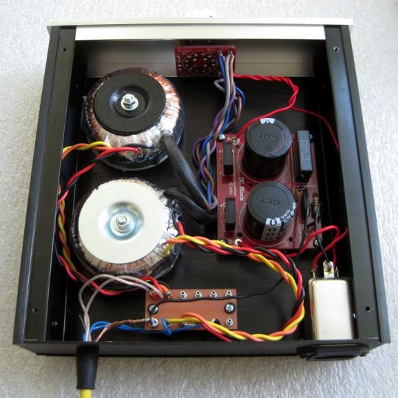
To test the new PCB out, I built a fancy remote AC power supply for a phono stage that holds its own high-voltage power supply and low-voltage heater power supply, so only a set of two AC voltages (12Vac and 240Vac) leaves the box. At the AC power input, the AC must travel through a fuse and an RFI trap network. Next, one of my Select-AC switches stagers the turn on of the AC outputs, with the heater power supply getting is AC first, then the high-voltage power supply. It works well.
Bear in mind that adding a DC-Block to an existing piece of commercially-made audio gear will no doubt void the warranty. Moreover, this is not a project for the beginner. Indeed, do not even think of using if you are not an experienced electronics practitioner. The DC-Block kit is available now that the GlassWare web store now.
Even More DVC Exploitation
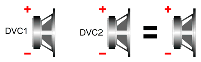
Well, in post 560, I showed how we could exploit a dual-voicecoil (DVC) woofer to make an asymmetrical crossover that yielded a highly damped 2nd-order high-pass filter for the delicate tweeter and a bumpy 1st-order low-pass filter for the woofer, which amazingly enough sums to frequency, phase, and impedance flat.
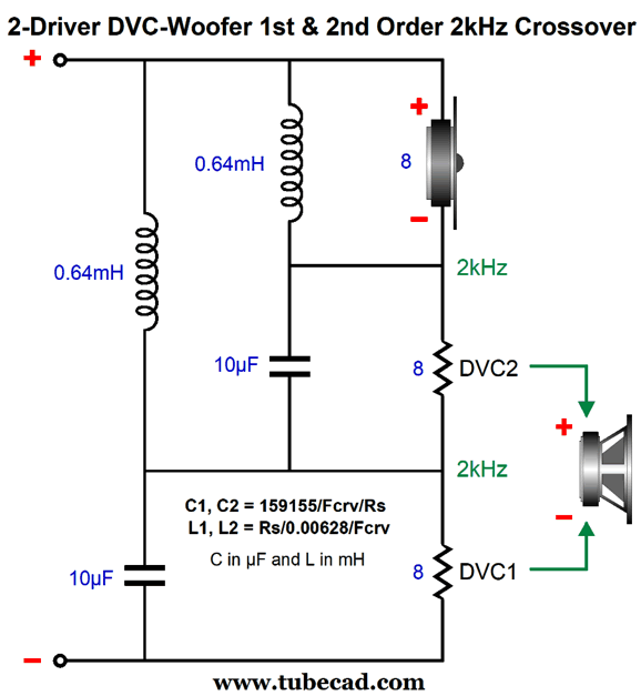
Effectively this crossover holds a three-way crossover with both crossover frequencies being the same, which in this example is 2kHz. The result is that tweeter sees the 2nd-order slope, while the first DVC voicecoil sees a 1st-order slope at the crossover frequency and its brother voicecoil sees a band-pass filter tuned to the crossover frequency. The two voicecoils combine to make a bumpy 1st-order slope for the woofer's cone. The question to ask next is: Well, can we further exploit having dual voicecoils? We can. For example, what if we added a DVC subwoofer to the mix?
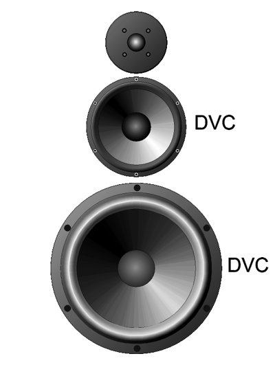
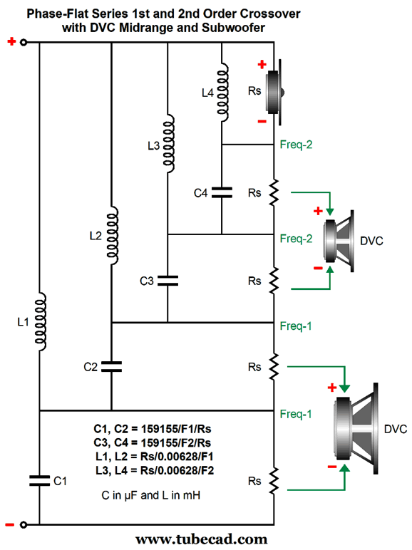
The eye sees three drivers, but the crossover required is effectively a four-way design that would normally be used with five drivers, but as each DVC driver is effectively two-drivers in one, we only need the three.
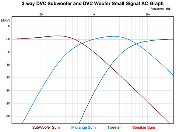
Note that there are only two crossover frequencies, not four. Let's pick for a design example the frequencies of 300Hz and 3kHz. The DVC subwoofer's cone will put out a bumpy 1st-order low-pass output at the first crossover frequency of 300Hz, while the DVC midrange will cut off at a 2nd-order slope at 300Hz, but produce a bumpy 1st-order low-pass slope at 3kHz. The tweeter's output is down -6dB at 3kHz and its slope is 2nd-order.
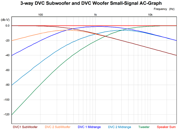
The important plotline is the speaker sum of the three drivers. The actual signal delivered to each voicecoil is shown in this graph.
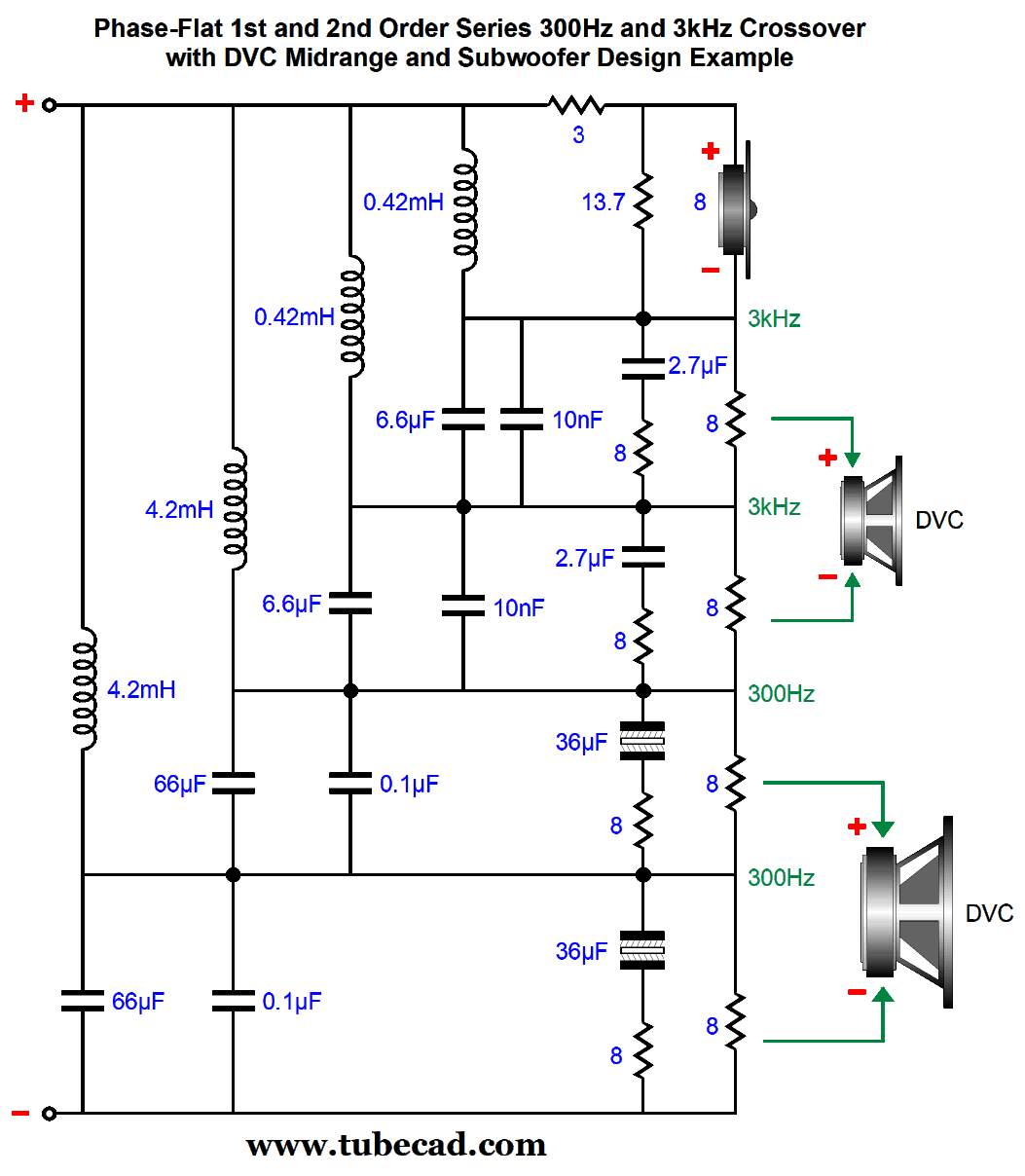
Note that the tweeter is down -120dB at 30Hz, as its cutoff slope goes from 2nd-order to 4th-order below 300Hz. This is a lot of protection for the tweeter. The DVC midrange's output is down -40dB at 30Hz and down -6dB at 300Hz. Once again, this driver gets a lot of protection from thumping bass notes. Just like the two-way version, this three-way version enjoys a frequency, phase, and impedance flat summation that works best with voltage-output amplifiers, but could be used with current-output amplifier due to its flat impedance. One problem that I know that will arise is that many believe that the ideal crossover network schematic is all that is needed to build an actual loudspeaker. It isn't. Why not? Speaker drivers are far from being 1% resistors. Woofers present a non-flat impedance plot, due to their series inductance (Le) and resonant frequency. Tweeters are often too efficient, so their output must be padded down to match the midrange and woofer's SPL. Thus, here is a closer-to-reality crossover.
The midrange I had in mind was the Aurum Cantus AC-180F1D 7-inch DVC driver and the 10-inch Dayton Audio SD270A-88 DVC subwoofer. I assume that the average tweeter would be about 4dB higher in SPL than the midrange and woofer, so I added a -4dB padding network. All the DVC voicecoils required Zobel networks to undo their intrinsic series inductance (Le). Ideally, the 10-inch and 7-inch drivers should share the same in-cabinet-resonant frequency and the same loading—say acoustic suspension or transmission line. If we do the math, we see that with both drivers in their separate acoustic suspension sealed enclosures with a Qtc of 1, places their Fc at around 62 Hz. A Qtc of 1 at 62Hz will sound quite punchy. If we desire a tamer bass and deeper bass response, we could shoot for 43Hz, which would give us a Qtc of 0.7 and a much bigger speaker enclosure.
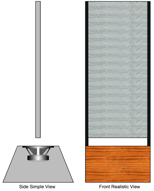
Bi-Amped Version Well, what if we return to something simpler: just a phase-flat active crossover for use with a powered subwoofer and an existing satellite loudspeaker. In post 560, I showed Magnepan loudspeakers getting a top-firing subwoofer with an active 120Hz crossover that delivered a 2nd-order slope for the Maggies and a bumpy 1st-order slope for the subwoofer.
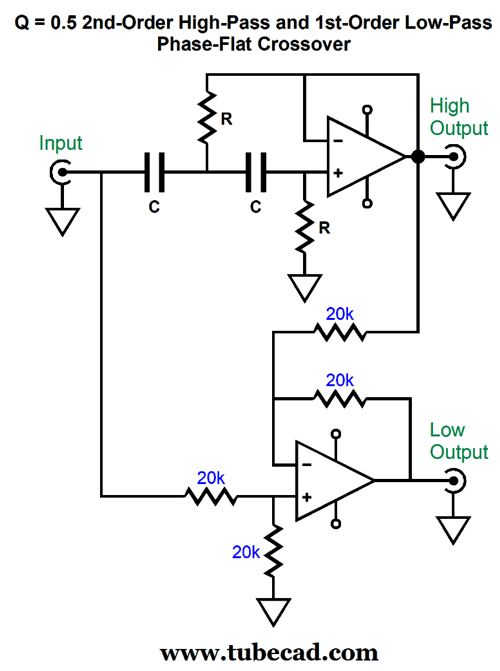
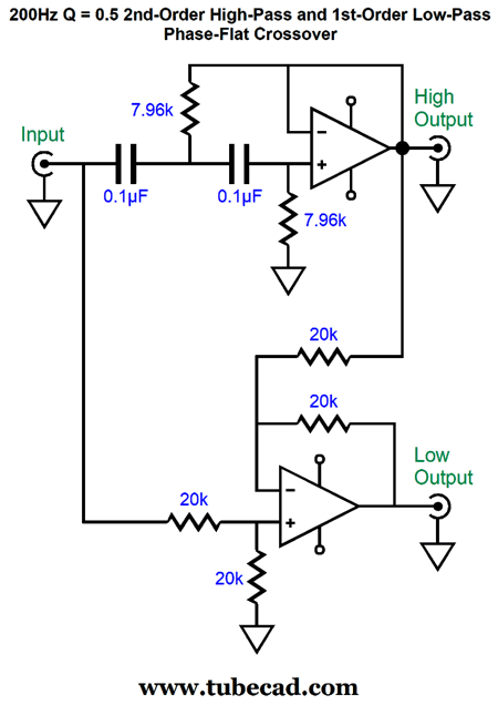
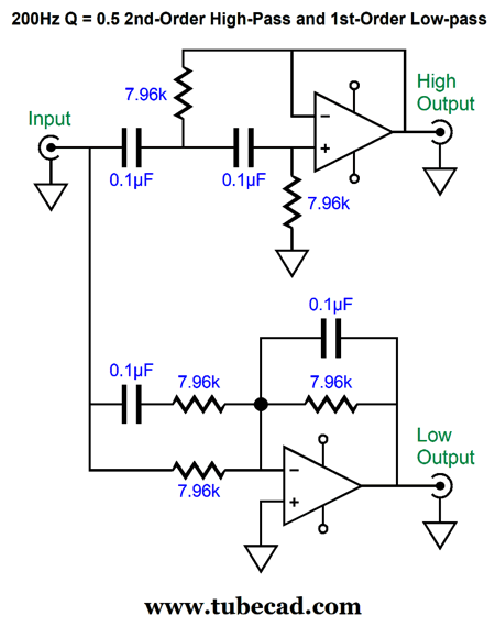
The formula behind the circuit is trivial: R = 159155/Fcrv/C where C is in µFs. Here is a design example with a 200Hz crossover frequency
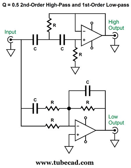
This circuit certainly works, but I wondered if I couldn't replace the differential amplifier that delivers the powered subwoofer its signal. Why? Differential amplifiers do not translate easily into useable tube circuits, as at least four triodes is needed. It took a little head scratching, but I came up with the following circuit for the bass output.
This circuit yields identical output to the previous version. The phase on the subwoofer, however, must be flipped at the driver's terminals, as the bottom OpAmp is configured in the inverting mode. Note that two extra capacitors are required, which is a liability, as tight-tolerance capacitors cost far more than 1% resistors. At the same, it is fabulous that all the resistor values are the same, as are all the capacitor values.
The formula behind the circuit is trivial: R = 159155/Fcrv/C where C is in µFs. Here are the SPICE-generated frequency plots.
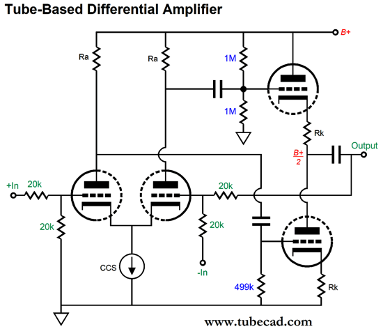
The high-frequency driver sees the damped 2nd-order slope and the subwoofer sees the bumpy 1st-order slope, which is just what we want. Okay, how do we translate this circuit into tubes? I wanted to use the fewest number of tubes possible, while still providing a low output impedance. The high-pass filter could be made from two cathode followers in cascade, each getting its own 1st-order high-pass RC filter. Alternatively, we could build a Salen-Key 2nd-order filter with a Q of 0.5. The subwoofer output signal requires a differential amplifier. Now, a decent differential amplifier can be made with triodes, but it requires at least four triodes.
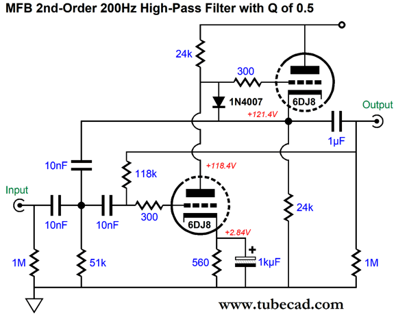
As long as the input stage's two triodes are well matched and both plate resistors share the same value, with the same holding true for the cathode follower's two triodes and cathode resistors, the common-mode-rejection ratio (CMRR) will prove quite good. Nonetheless, I would prefer to use one twin-triode. Here is what I came up with for the high-pass filter:
It's not a Salen-Key topology, but a multiple-feedback filter (MFB) that inverts the input signal at its output. This topology requires an additional capacitor compared to the Salen-Key topology but, in return, we get better performance. The 1µF output coupling capacitor ensures that its own high-pass filter action won't interfere with the much higher crossover frequency, but we could use a larger value if need be. The formulas for the resistor values are as follows: R1 = 159155/C/Fcrv/1.5 R2 = (159155/C/Fcrv)1.5 Where C is in µF. Resistor R2 is the resistor that connects to the output. Next, we look at the subwoofer's circuit.
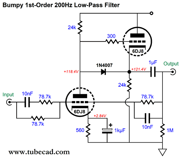
Once again, we see input and output triodes being 6DJ8 types. Not shown, embarrassingly enough, is the 240Vdc B+ voltage. This is not a differential amplifier circuit. The input triode is configured in the grounded-cathode amplifier topology, while the ECC99 functions as a cathode follower. In other words, this is a constant-current-draw amplifier (CCDA). Combined, the two stages create an inverting amplifier stage. The two 10nF (0.01µF) capacitors along with the 78.7k resistors set the 200Hz crossover frequency. The math is easy: R1 = 159155/C/Fcrv (The math tells us that, actually, 79577 ohms is the right value, but reality informs us that 78.7k is the closest 1% resistor value.) The 1N4007 rectifier, in either circuit, is simplify there to prevent tube damage at startup, when the triodes are cold and yet to conduct current. In other words, the diode prevents the cathode follower's triode from seeing the full B+ voltage on its grid while its cathode is at ground potential. Once the tube is hot and conducting, the diode is no longer forward biased, and it drops out of the circuit. The 1µF output coupling capacitor will work well with power amplifiers whose input impedance is at least 30k. If the impedance is much lower, a larger-valued coupling capacitor will be needed. All in all, I love this arrangement. It yields the same flat-frequency and phase-flat output as the solid-state alternative, but with more warmth and charm.
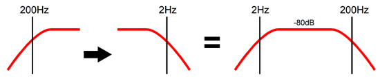
Internally-Powered Subwoofer Imagine a stereo system wherein a small active 200Hz high-pass, 2nd-order filter receives its input signal from a line-stage amplifier or streaming DAC, and the existing power amplifier sees the bass-empty input signal, which it amplifies and, then, drives the speaker drivers. If the subwoofer were external to the loudspeaker, then the same active crossover box would offer a subwoofer output signal. In contrast, if the loudspeaker holds its own internally powered subwoofer, where does the internal power amplifier get its input signal? We could run a long length of interconnect back to the line-stage amplifier, but that would be a pain. The better solution is massage the signal that arrives at the loudspeaker's input terminals so that the missing bass might be reconstituted. How is that possible? We deliver the signal at the input terminals to a 2nd-order 2Hz low-pass filter, which will effectively boost the frequencies below 200Hz down to 2Hz, whereupon the 2nd-order high-pass filtering will still obtain.
The only problem is that we do not want a 2nd-order Linkwitz-Riley low-pass 200Hz filter for the internal subwoofer, as we desire a phase-flat crossover, which requires a bumpy 1st-order 200Hz low-pass filter. The solution is to impose a stop at 200Hz on one of two 200Hz low-pass 1st-order filters.
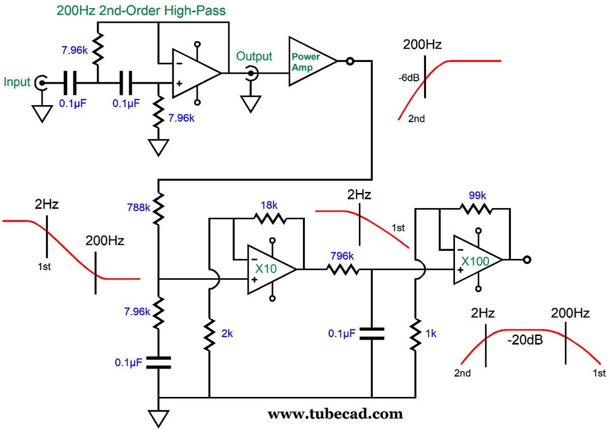
Yes, it is a head scratchier. The top Salen-Key 200Hz high-pass filter with a Q of 0.5 is easy enough to conceptualize. Its output signal drives the external power amplifier, which in turn drives the midrange and tweeter. The filtered and amplified signal is then passed through the 2Hz-to-200Hz shelving network. Next, the OpAmp amplifies the signal by ten before passing it along to the 2Hz low-pass filter, which is then amplified by 100 by the following OpAmp. The result is a band-pass signal that falls off at -12dB per octave below 2Hz and -6dB per octave above 200Hz. The missing bass signal has been restored (re-inflated with bass signal). Wait a minute, John, where's the bump? Adding the missing bump is easy enough.
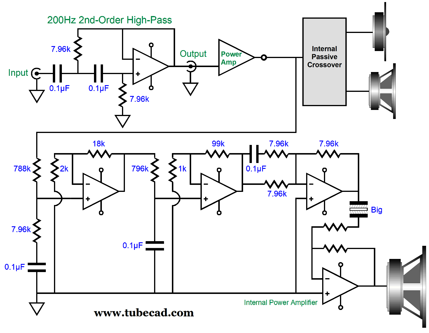
The added inverting OpAmp and its frequency-bumping network at its input impose the missing bump. The final OpAmp's output is capacitor coupled to prevent any DC offsets from being passed on to the internal subwoofer power amplifier. Do not forget that the bass restoration required a DC gain of 1000 (60dB), which would turn a 1mV DC offset into a 1Vdc offset at the input of the internal subwoofer power amplifier. Not good. In fact, it wouldn't hurt to add an input coupling capacitor to the input of the bass restoration circuit. The 788k resistor requires only a 1µF coupling capacitor to provide bandwidth down to 0.2Hz. The output signal leaving the final OpAmp is only one tenth of the level that entered the loudspeaker, so the internal power amplifier must make up the required difference. This amplifier was configured in the inverting style to atone for the phase inversion from the last OpAmp. A non-inverting power amplifier could certainly be used, if the subwoofer's positive and negative terminals were reversed. As much as I love this setup, I must point out that the rest of the stereo system must be noise-free, as any wall-frequency hum or power-supply noise will be aggressively amplified by the bass-restoration circuit. Silence is, indeed, golden. By the way, using a lower crossover frequency, say 80Hz to 100Hz, would at least halve the hum boosting. (The 200Hz crossover is the result of my still thinking about how best to add a subwoofer to the Maggie loudspeakers.)
Music Recommendation: Musica Nuda
And two albums, the 2019 album, My Favorite Tunes, is the one I used to evaluate the headphone amplifier, as this live recording of her singing and him playing an upright bass is thrilling to behold. If you didn't try listening to Musica Nuda after my first recommendation, I don't know what to do with you, as this is the stuff that audiophile dreams are made of.
//JRB
Did you enjoy my post? Do you want to see me make it to post 1,000? If so, think about supporting me at Patreon.
User Guides for GlassWare Software
For those of you who still have old computers running Windows XP (32-bit) or any other Windows 32-bit OS, I have setup the download availability of my old old standards: Tube CAD, SE Amp CAD, and Audio Gadgets. The downloads are at the GlassWare-Yahoo store and the price is only $9.95 for each program. http://glass-ware.stores.yahoo.net/adsoffromgla.html So many have asked that I had to do it. WARNING: THESE THREE PROGRAMS WILL NOT RUN UNDER VISTA 64-Bit or WINDOWS 7, 8, and 10 if the OS is not 32-bit or if it is a 64-bit OS. I do plan on remaking all of these programs into 64-bit versions, but it will be a huge ordeal, as programming requires vast chunks of noise-free time, something very rare with children running about. Ideally, I would love to come out with versions that run on iPads and Android-OS tablets.
|
I know that some readers wish to avoid Patreon, so here is a PayPal button instead. Thanks.
John Broskie
John Gives
Special Thanks to the Special 77 To all my patrons, all 77 of them, thank you all again. I want to especially thank
All of your support makes a big difference. I would love to arrive at the point where creating my posts was my top priority of the day, not something that I have to steal time from other obligations to do. The more support I get, the higher up these posts move up in deserving attention.
If you have been reading my posts, you know that my lifetime goal is reaching post number one thousand. I have 444 more to go. My second goal was to gather 1,000 patrons. Well, that no longer seems possible to me, so I will shoot for a mighty 100 instead. Thus, I have just 23 patrons to go. Help me get there. Thanks.
Support the Tube CAD Journal & get an extremely powerful push-pull tube-amplifier simulator for TCJ Push-Pull Calculator
TCJ PPC Version 2 Improvements Rebuilt simulation engine *User definable
Download or CD ROM For more information, please visit our Web site : To purchase, please visit our Yahoo Store: |
|||


| www.tubecad.com Copyright © 1999-2021 GlassWare All Rights Reserved |