| John Broskie's Guide to Tube Circuit Analysis & Design |
12 August 2022 Post Number 563
Thanks to those who have donated to my efforts. I cannot guarantee that you will thereby be granted entry into Heaven, but I am inclined to bet on it. Thanks again. As for the 99.99% of regular readers who didn't....
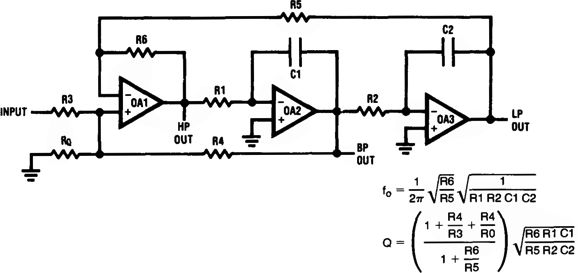
National Semi 2nd-Order Phase-Flat Crossover
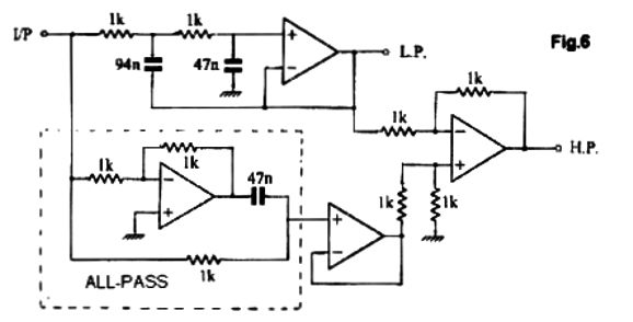
The circuit that generated these plotlines appeared in National Semiconductor's book, Linear Applications Handbook, 1994, on page 826.
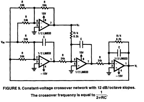
The amazing thing is that I failed to see it back in 1994. (I used to own almost ten linear feet of data books, nine and a half feet of which I left behind when we moved to Colorado.) Perhaps, my version of the handbook was too old or I did see it, but failed to grok its significance, as many filters have been made with four OpAmps —but those filters designs usually offer three outputs: low-pass, band-pass, and high-pass. Here is an example:
In contrast, this circuit delivers two outputs: low-pass and high-pass. More importantly, just like the Kreskovsky transient-perfect 2nd-order crossover topology , it bestows a flat phase response, in spite of its 2nd-order slopes. Let's start by redrawing the schematic.
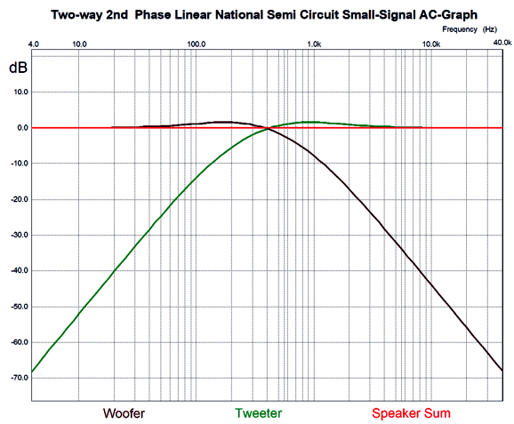
Three identically valued capacitors and only two resistor values are needed. I normalized the formulas to the 30k resistor value. Note that the other resistor value (12k) is one fourth as large as the 30k value. This ratio must hold. Other commonly available resistor values that hold to the 4-to-1 ratio are 3k to 750, 12k to 3k, 56k to 14k, 102k to 25.5k, and 120k to 30k. Some come dang close, such as 100k to 24.9k and 200k to 49.9k. The larger the resistor values, the smaller the capacitor value will be to realize the same crossover frequency. To test the circuit in SPICE, I used 12k and 3k and 33nF, which implied a crossover frequency of 402Hz. Here is what SPICE revealed.
The summed phase was flat within 0.003 degrees from 4Hz to 40kHz. The frequency response was even flatter. I tested the transient response and it passed the test.
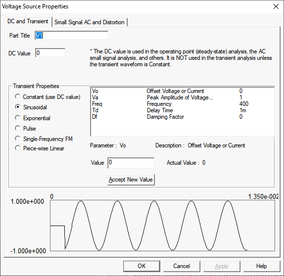
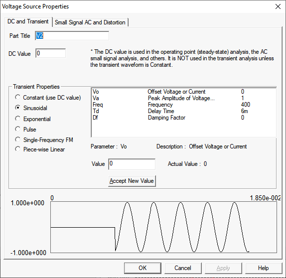
I had entered a tone burst of two-cycles of 400Hz. By the way, the easy way to generate such an input signal in SPICE is to place two voltage signal sources in series, but out of phase with each other and then stagger the turn-on times.
The non-inverting source turns on after a 1-millisecond delay; then after two cycles are complete, the second source turns on, thereby canceling the first source's output, making a two-cycle tone burst. The next and harder test was square-waves.
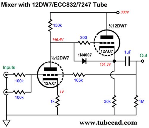
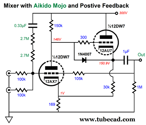
A square-wave goes in and comes out square. Note that the high-frequency driver must endure more than twice the input signal peak magnitude, while the low-frequency driver only sees a bit more magnitude. In addition, note that the high-frequency driver must exhibit an infinite rise time. Is it any wonder that square-wave testing of loudspeakers results in burnt tweeters? Of course, I cannot look at a solid-state circuit and not try to image it translated into tubes. As I looked the circuit over, I saw that an excellent tube-based mixer circuit would be needed, as the high frequencies left its output. In other words, I had a hybrid circuit in mind, with the high frequencies getting tubes; the low frequencies, solid-state OpAmps. A feedback-based mixer requires high open-loop gain and a low output impedance. My preference is for the fewest triodes possible, which immediately brought to my mind the dissimilar twin-triode tube the 12DW7/ECC832, which holds both a 12AX7 and a 12AU7 triode.
The input triode is configured as a grounded-cathode amplifier and the output triode is arranged as a cathode follower. The 105k resistor was needed to bring the output up to unity-gain with the 100k input resistors. The 1N4007 safety diode protects the 12AU7 triode at start-up. Overall, this mixer works fairly well, but it could be improved upon. I decided to add some positive feedback to increase the open-loop gain and to inject some Aikido mojo to improve the weak PSRR.
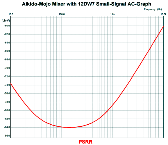
A small sampling of the B+ voltage ripple is delivered to the mixer's input and it forces a power-supply-noise null at the output, which improves the PSRR over the plain version by 50dB.
Without the Aikido-Mojo, the PSRR is only -34dB. Musicians and home recorders take note: this is the mixer you want. The cathode follower's cathode resistor is terminated into the 12AX7's cathode, not ground, so 12AX7 realizes greater amplification. Now that we have a hotrodded mixer, we can add the OpAmps.
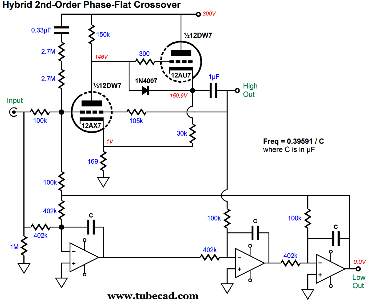
This hybrid circuit is functionally equivalent to the original circuit, but adds the otherwise missing soft glow. I feared that the 1µF output coupling capacitor would throw the circuit off, but in SPICE simulations, it worked almost as well as the entirely-solid-state version, with the summed output being within 0.0015dB from 10Hz to 100kHz.
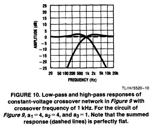
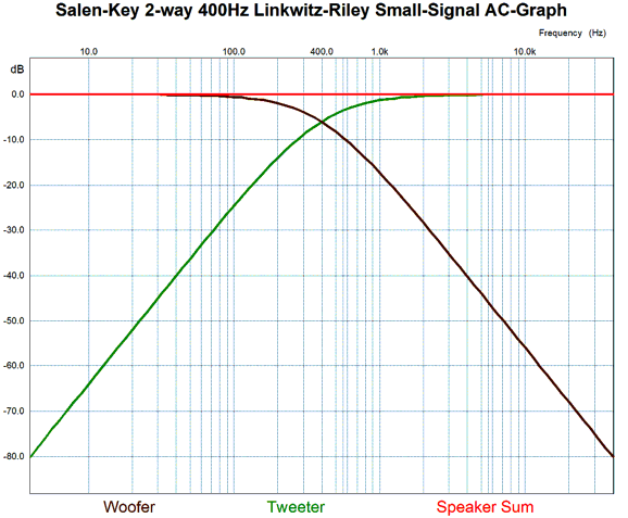
Okay, what are we to make of this circuit and concept? First, it works. It delivers a flat frequency and phase response. It requires relatively few parts and only three tight-tolerance capacitors—all of the same value. The downside to the active crossover is that the same that applied to the Kreskovsky transient-perfect 2nd-order crossover topology—namely, it isn't so much a crossover as an over-lapper. At the crossover frequency, both drivers are down only 0.2dB. At one decade away from the crossover frequency, the drivers are down only -28dB. Before reaching the crossover frequency, both drivers must undergo a +1.7dB bump to create the flat output. In contrast, in the other famous 2nd-order crossover, the Linkwitz-Riley, both drivers are down -6dB at the crossover frequency and, one decade away from the crossover frequency, the drivers are down almost -40dB.
That 12dB difference may not seem like that much, but remember that -12dB equals a quartering of the AC voltage delivered to the driver's voicecoil, which translates into 1/16th as much power dissipated. It's time to get the bird's-eye view. The reason we use crossovers, both the active and passive kinds, is that the high-frequency drivers are fragile and powerful bass notes are dangerous to their health. Thus, I could only see this crossover being used with robust high-frequency drivers, say a loudspeaker with two identical fullrange drivers with a crossover of 500Hz; or, with a truly high crossover frequency, say 5kHz with a 1-inch dome tweeter. Think of it this way: a crossover frequency of 1kHz is effectively a crossover frequency of 500Hz for the high-frequency driver and 2kHz for the low-frequency driver; think half and double.
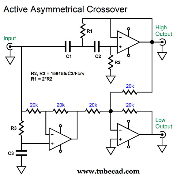
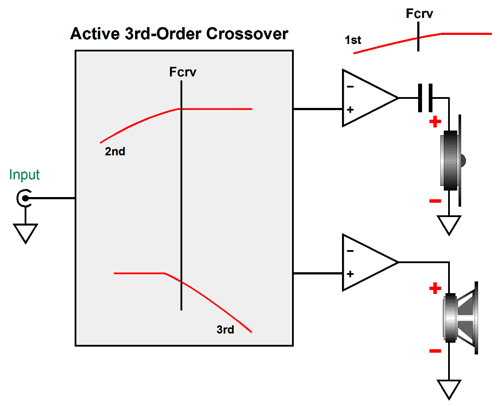
Active Asymmetrical Crossover
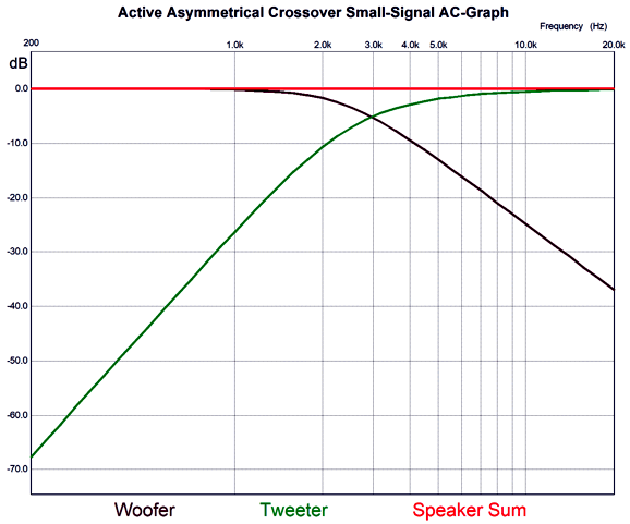
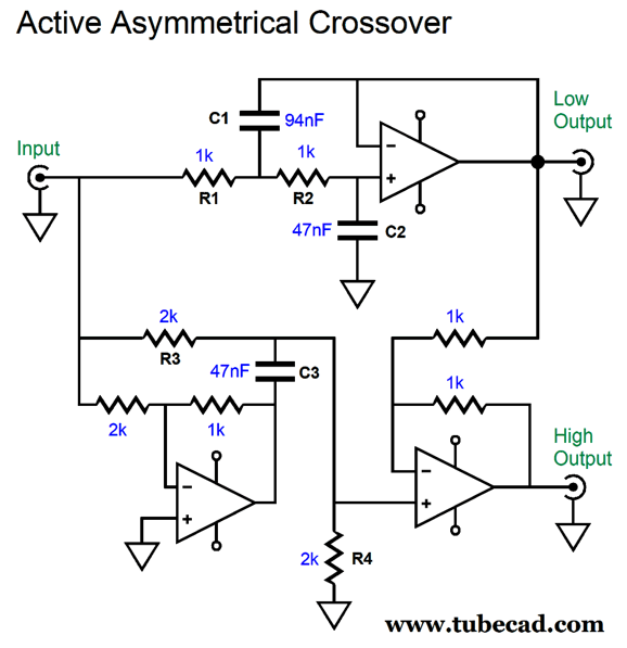
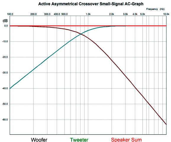
I do not know where it came from, but it looks like it came out a Journal of the AES article, save for the ground symbol used, which looks decidedly British, which in turn makes the esteemed magazine, Wireless World, the most likely source. I tried searching the web for the image with tineye.com, but nothing came up. I do not remember how the schematic ended up on my hard-drive, but I would bet that some reader emailed to me. Okay, moving on to the circuit, this two-way crossover delivers asymmetrical slopes, with the low-pass section realizing a 2nd-order Butterworth and the high-pass portion following a 3rd-order cutoff (with what looks like a Bessel alignment). Here are the SPICE-generated plots.
The crossover appears to be about 3kHz, as that is where the two plots intersect. But based on the summed phase plot line, the actual crossover frequency is closer to 3.4khz. The summed frequency response is ruler flat, but not phase flat. Nonetheless, the 3rd-order high-pass output is highly desirable, as it affords so much more protection for the tweeter. (Think of a two-way speaker with a horn mid-tweeter and 15-inch woofer.) As looked the circuit over, I saw that we could lose one OpAmp.
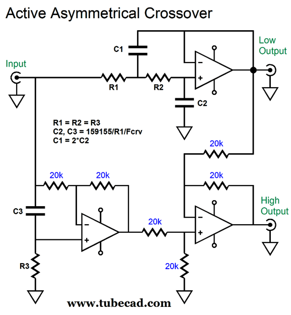
Resistor R3 is doubled in value, while the equal valued resistor R4 takes the place of the fourth OpAmp. As I stared at it a bit longer, I realized that we can rearrange the circuit thus:
Capacitor C3 and resistor R3 perform the required frequency-dependent phase shifting, wherein DC voltage and low frequencies are inverted by the OpAmp, but high frequencies pass through in phase. With ease we can flip the asymmetry, so the low-pass output gets the 3rd-order slope, while the high-pass sees a 2nd-order slope.
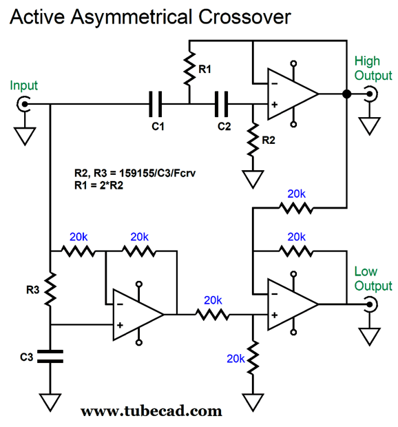
This arrangement might come in very handy with a powered subwoofer and satellite system, where we want the sluggish subwoofer to get out of the way as soon as possible. Well, after a bit more pondering, I saw that we could lose the differential amplifier and use a simple mixing circuit instead.
Note that capacitor C3 and resistor R3 have switched places. Of course, we can flip the asymmetry on this arrangement as well, so the high-pass output is 2nd-order, while the low-pass is 3rd-order.
As you can readily see, once I get started, there's no end to circuit variation. Here is the resulting graph for the circuit.
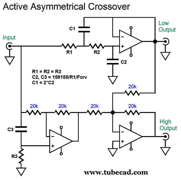
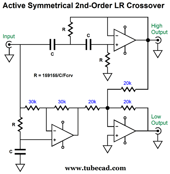
The crossover frequency is 1kHz. We can see that the woofer cuts off far more steeply than the tweeter in this arrangement. I wondered about the Butterworth alignment of the 2nd-order low-pass filter and wondered what would happen if a Linkwitz-Riley alignment with a Q of 0.5 were used instead of the Butterworth's Q of 0.707. Interestingly enough, the asymmetry is banished and the crossover becomes a symmetrical two-way, 2nd-order Linkwitz-Riley.
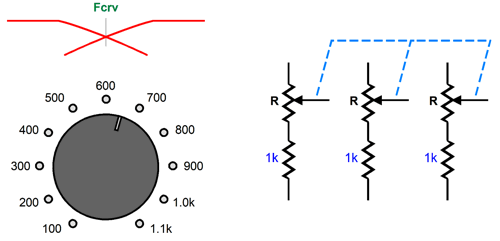
Only three equal valued resistors and three equal valued capacitors are needed to set the crossover frequency. This makes life much easier, as we only need to swap resistor values to set a new crossover frequency. Imagine a piece of test equipment that delivered a two-way, 2nd-order Linkwitz-Riley crossover for testing the best crossover frequency between two drivers. All that would be needed is a three-ganged potentiometer with equal linear-taper resistances.
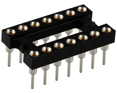
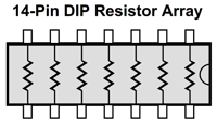
Once the best crossover frequency was found, we could either design a passive or active a two-way, 2nd-order Linkwitz-Riley crossover based on that frequency. Okay, here is another idea: what if an active a two-way, 2nd-order Linkwitz-Riley crossover was sold that held a 14-pin DIP socket on its PCB, which would allow us to plug in 7-resistor array chips.
In other words, these readily available 1% resistor arrays would set the crossover for two channels, with one extra resistor in between.
I can imagine several situations where this might come in handy for an audiophile, but it certainly we be a huge bonus for the maker of active crossovers. I just did a quick search of Mouser.com and saw that they offer 1436 different 0.1% 7-resistor array chips. Here is a table that shows the crossover frequency with a 0.1µF capacitor.
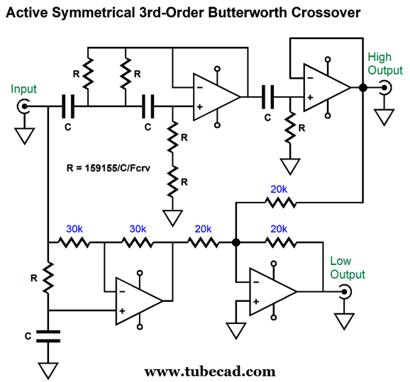
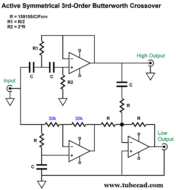
If a 10nF capacitor is used instead, all the resistor values must be increased by tenfold. Moving on, my next thought was: Wouldn't this arrangement also work well with the 3rd-order Butterworth filter? Indeed it does.
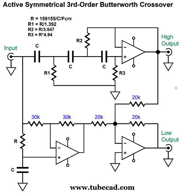
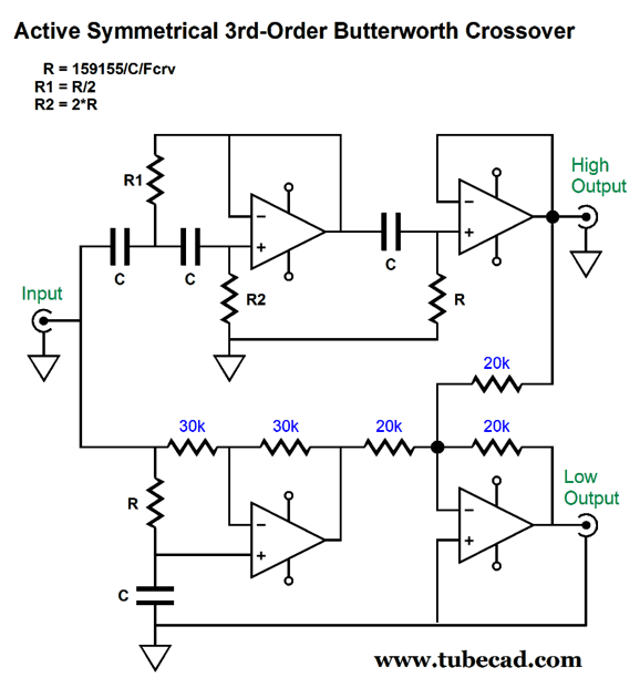
The two-way 3rd-order crossover is not phase flat, but it does sum to frequency flat and it provides great tweeter protection. Sadly, the resistor-array trick cannot be used, as resistors R1, R2, R3 all differ in value. Or can it be used? If we add an extra OpAmp, we might be able to use the same resistor values throughout.
The 2nd-order high-pass filter exhibits a Q of 1, while the following 1st-order filter produces a Q of 0.707. Cascading Qs multiply, so the final Q is 0.707, i.e. a Butterworth 3rd-order. The resistors still differ in value, but differ by a factor of two, which means that we can place some resistor in series and other in parallel.
Thus, we are back to being able to use resistor array chips, but we will need one 7-resistor array per channel. I can see this arrangement working beautifully with a subwoofer and satellite loudspeaker or between a woofer and midrange, but not between a midrange and a tweeter. Why not? The poor tweeter might burn up. Directly coupling a power amplifier to tweeter is dangerous, as a poor connection of an RCA plug can produce a huge 60Hz hum that will rip the tweeter apart. The safe workaround is still to give the tweeter some coupling capacitor protection.
The tweeter gets a 1st-order capacitor tuned to the crossover frequency, while the active crossover delivers the 2nd-order high-pass filter with a Q of 1. As far as the tweeter is concerned, it is being fed a 3rd-order Butterworth high-pass filtered signal. With the capacitor in series with the tweeter, the power amplifier can scream with 60Hz hum and the tweeter will probably survive. Here is what the active crossover looks like:
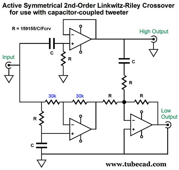
Where's the missing OpAmp? We do not need it, as the mixer can perform the same function. While on the topic of capacitor-coupled tweeters in a bi-amped setup, here is the 2nd-order version.
By the way, I tried using a Bessel alignment in place of the Butterworth. Not good. The high-pass filter still cuts off at a 3rd-order slope, but the low-pass output falls off in an odd staggered slope that begins as 3rd-order but then shifts to 2nd-order and ends in 1st-order. In contrast, the Gaussian alignment worked, but the low-pass output was 1st-order throughout. The summed output was ruler flat, but the phase was not. One advantage, however, to the Gaussian high-pass filter is that the high-pass output was down -7.4dB at the crossover frequency, whereas the Butterworth is down -3dB. In short, stick with the Butterworth alignment. Another by the way, note how one "seed" circuit soon blossoms into a field of circuit variations. And each new variation can spawn another dozen circuit, which in turn can...
Music Recommendation: Pasquale Grasso's Pasquale Plays Duke Amazon Music streaming service offer this album in 24-bit, 96kHz. Well worth hearing.
//JRB
Did you enjoy my post? Do you want to see me make it to post 1,000? If so, think about supporting me at Patreon.
User Guides for GlassWare Software
For those of you who still have old computers running Windows XP (32-bit) or any other Windows 32-bit OS, I have setup the download availability of my old old standards: Tube CAD, SE Amp CAD, and Audio Gadgets. The downloads are at the GlassWare-Yahoo store and the price is only $9.95 for each program. http://glass-ware.stores.yahoo.net/adsoffromgla.html So many have asked that I had to do it. WARNING: THESE THREE PROGRAMS WILL NOT RUN UNDER VISTA 64-Bit or WINDOWS 7, 8, and 10 if the OS is not 32-bit or if it is a 64-bit OS. I do plan on remaking all of these programs into 64-bit versions, but it will be a huge ordeal, as programming requires vast chunks of noise-free time, something very rare with children running about. Ideally, I would love to come out with versions that run on iPads and Android-OS tablets.
|
I know that some readers wish to avoid Patreon, so here is a PayPal button instead. Thanks. John Broskie
John Gives
Special Thanks to the Special 77 To all my patrons, all 77 of them, thank you all again. I want to especially thank
All of your support makes a big difference. I would love to arrive at the point where creating my posts was my top priority of the day, not something that I have to steal time from other obligations to do. The more support I get, the higher up these posts move up in deserving attention.
If you have been reading my posts, you know that my lifetime goal is reaching post number one thousand. I have 440 more to go. My second goal was to gather 1,000 patrons. Well, that no longer seems possible to me, so I will shoot for a mighty 100 instead. Thus, I have just 23 patrons to go. Help me get there. Thanks.
Support the Tube CAD Journal & get an extremely powerful push-pull tube-amplifier simulator for TCJ Push-Pull Calculator
TCJ PPC Version 2 Improvements Rebuilt simulation engine *User definable
Download or CD ROM For more information, please visit our Web site : To purchase, please visit our Yahoo Store: |
|||||||||||||||||||||||||||||||||||||||||||||||||||||||||||||||||||||||||||||||||||||||||||||||||||||||||||||||||||||||||||||||||||||||||||||||||||||||||||||||||||||||||||||||||||||||||||||||||||||||||||


| www.tubecad.com Copyright © 1999-2022 GlassWare All Rights Reserved |