| John Broskie's Guide to Tube Circuit Analysis & Design |
21 August 2022 Post 564
The Last DVC Design (For Now)
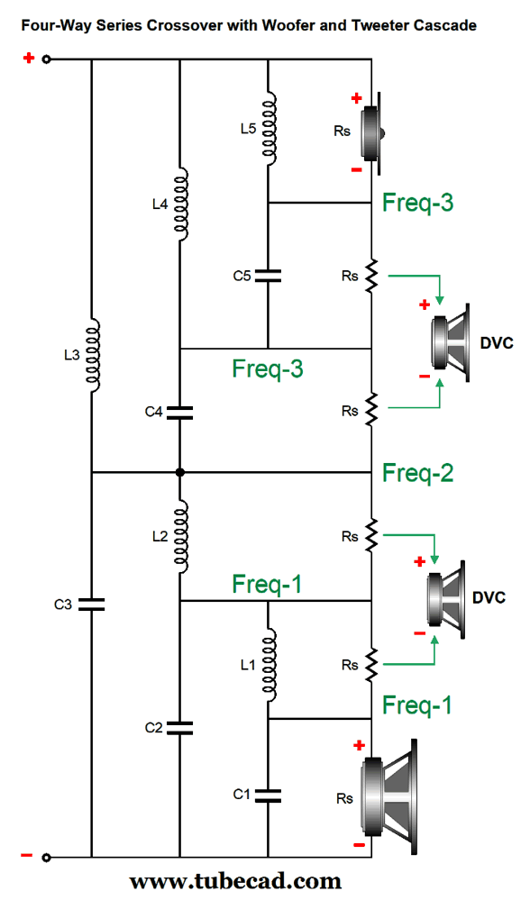
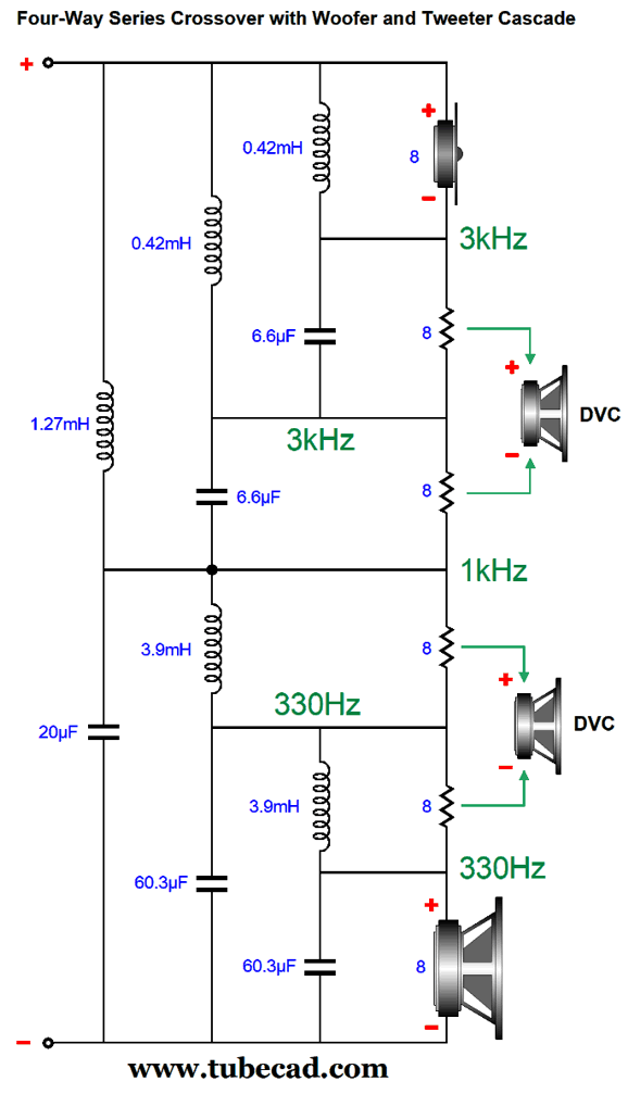
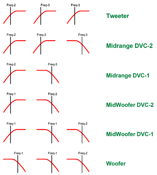
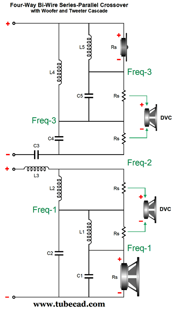
The crossover delivers a flat frequency, phase, and impedance. The crossover frequencies I choose are 330Hz, 1kHz, and 3kHz. Note that 1000/330 equals 3000/1000. The result of doubling up on crossover frequencies at 330Hz and 3kHz is that both the subwoofer and tweeter see initially 2nd-order slopes and, then, 3rd-order slopes as the middle 1kHz crossover frequency is encountered. This means that the slow subwoofer gets out of the way sooner and the delicate tweeter lives to play another song. Here is the crossover.
The math is super simple:
Let's fill in the part values for the three crossover frequencies (330Hz, 1kHz, and 3kHz), assuming 8-ohm drivers throughout.
Breaking down the various crossover slopes requires but a simple graphic presentation.
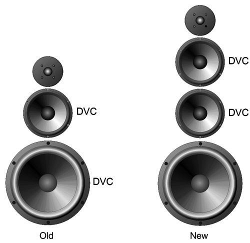
Each DVC voicecoil is effectively a separate driver as far as the crossover is concerned, so when designing the crossover it's better to think about the array of drivers holding six drivers, not four. But when it comes to acoustic output, there are only four drivers, so when evaluating the crossover in SPICE, we must combine the two DCV voicecoil outputs into one.
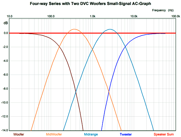
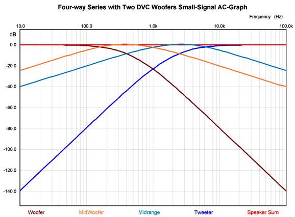
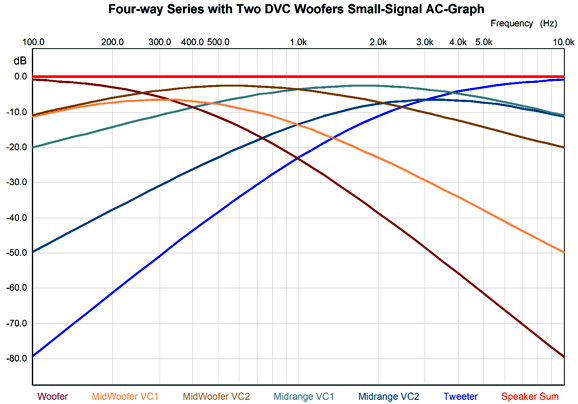
Both the subwoofer and tweeter are down more than -6dB at their first crossover frequency. Although both DVC drivers deliver a bumpy output, the sum of the four driver outputs results in a ruler-flat output (assuming ruler-flat drivers that is). This is a close-up view, so it is difficult to see that the subwoofer and tweeter see 2nd-order slopes, then 3rd-order slopes, while the DVC drivers see 1st-order slopes, which the following graph better reveals. At 100Hz, the tweeter is down by almost -80dB, which translates as 1/10,000 of signal delivered to the loudspeaker terminals. For example, 100W into an 8-ohm load translates into 40Vpk, so 40/10000 equals 4mV. Likewise, the subwoofer's output is down almost -80dB at 10kHz. Here is a graph that shows what each DVC voicecoil sees.
Practically, we can view the loudspeaker of consisting of two sections, a low one and a high one, with a 1st-order crossover at 1kHz separating the two. This brings up the possibility of bi-wiring the loudspeaker by altering the crossover into a parallel-series configuration.
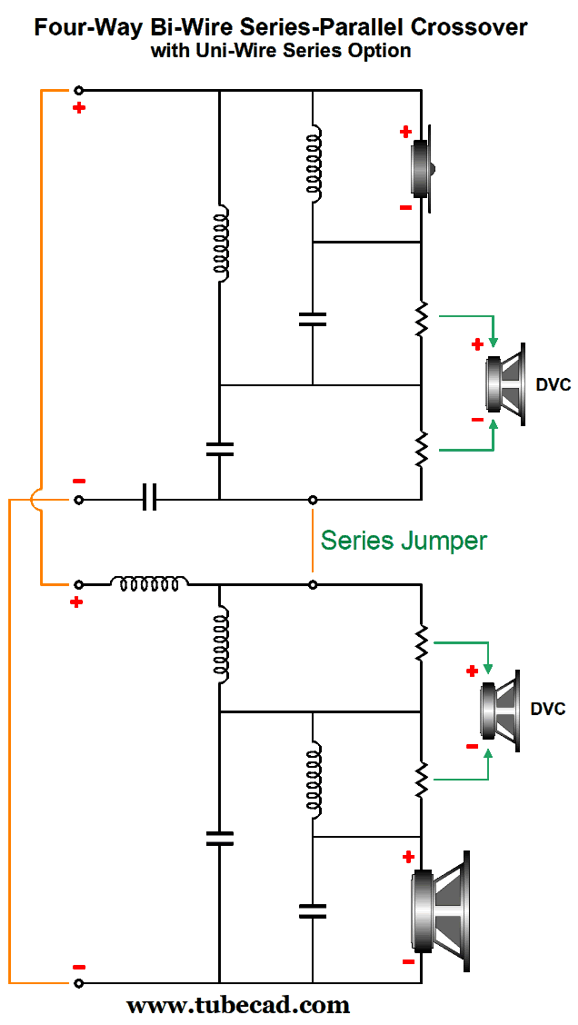
Capacitor C3 and inductor L3 are arranged in parallel, while all the other crossover components are arranged in series. Some will scratch their heads upon seeing capacitor C3 located on the negative side and not the positive side of the upper crossover. It may trouble your eyes and mind, but the speaker is entirely indifferent to this arrangement, as the exact same filtering occurs. So why didn't I place capacitor C3 up at the top, where most would expect it to appear? I wanted to grant the option of a fully series arrangement when mono-wiring the loudspeaker. How's that possible?
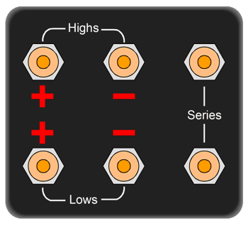
Placing the positives and negatives in parallel and adding a jumper wire creates an entirely series crossover. How do we gain access to the crossover to install the jumper wire? This way:
Six speaker terminals are needed, not the usual four for bi-wire and bi-amp setups. If we wish to bi-amp, we can. If we wish to run a parallel-series arrangement, we can. And if we wish to use a single loudspeaker cable and run a series crossover, we can. A damn elegant solution, don't you think?
As I see it, the two DVC drivers will handle the bulk of the music, with the subwoofer and tweeter filling in the remaining portion of the music spectrum. Since the two DVC drivers are identical, and since the spacing between them is only 7 inches, the 1st-order 1kHz crossover should meld gloriously well.
Minimalist Stage Amplifier
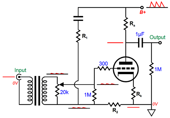
In addition, the input signal transformer would allow using my Aikido-Mojo technique from post 486.
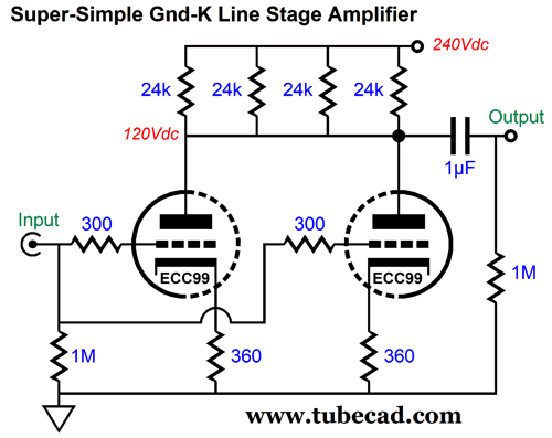
Since the input transformer breaks the ground connection to the signal source, we can float the secondary and volume control potentiometer and inject some power-supply noise into the mix sufficient to create a power-supply-noise null at the output. I was thinking along the lines of a triode-connected EL86 pentode or a Russian 6C19 triode or an American 12A4 triode. But the more I thought about it, the 5687 or ECC99 might prove the better choice.
Each triode gets its own cathode resistor, but both share the same 6k plate resistor. Yes, you do see four plate resistors, but the parallel value is 6k. Why? one answer is dissipation, as 2.4W of heat results from 120V drop across a 6k resistance, so each 24k would only dissipate 0.6W. Moreover, I could use four different types of 24k resistors: carbon-composition, carbon-film, metal-film, and wire-wound. Why? Blending the four types might result in a more neutral sonic flavor. Imagine a linestage with just two tubes.
I would give each ECC99 tube its own 12V regulated and floating power supply. Each channel will draw 20mA and the output impedance is 3k, which is plenty low for most systems.
State Variable Filter
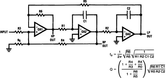
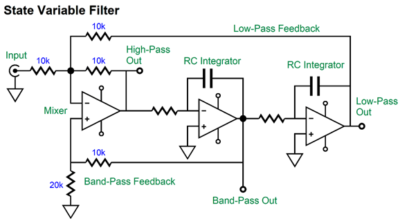
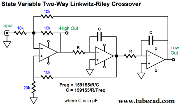
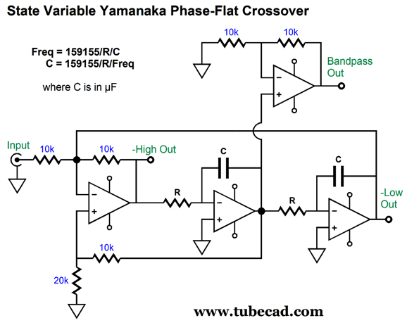
With this circuit we can make an active two-way Linkwitz-Riley active crossover for bi-ampping.
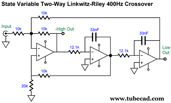
Note the negative sign on the high-pass output, which is there to remind us that we must invert the phase of the tweeter to sum to a flat output; failing to do so results in a deep suck-out at the crossover frequency. Since 33nF (0.033µF) 1% capacitors are readily available, it's a good value to use. The following design example shows how two 12.1k resistors create a 400Hz crossover frequency.
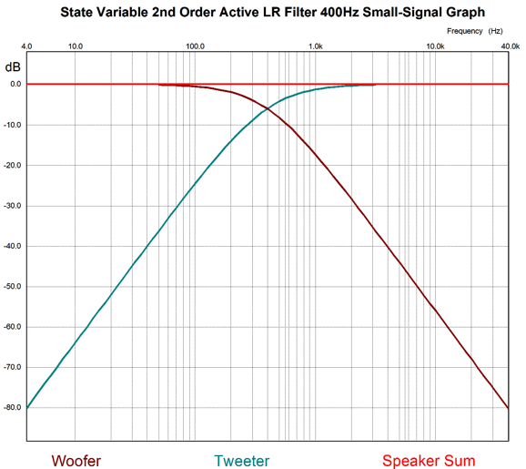
Here is the SPICE-generated graph for this active crossover.
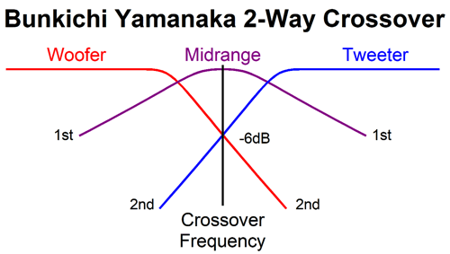
Note that both the woofer and the tweeter are down -6dB at the crossover frequency. The Linkwitz-Riley crossover sums to frequency flat, but it is not phase flat. If we desire phase flat, we must place the tweeter in phase with the woofer and then add a filler driver to fill in the suck-out. In other words, the speaker will be still effectively a two-way design, but three drivers are needed.
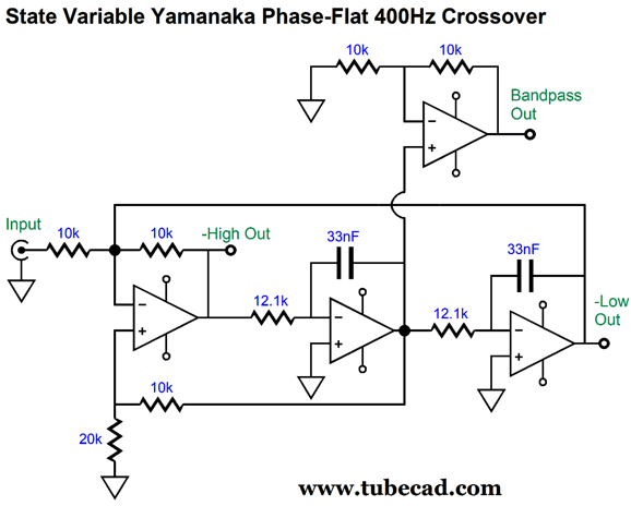
See post 475 and post 544 for more information on the Yamanaka crossover. The state-variable's band-pass output delivers the needed band-pass signal for the filler driver, but it is down by -6dB. This is only a problem if we cannot lower the gain by 6dB for the woofer and tweeter amplifiers or if the filler driver does not offer +6dB more SPL on its own. Since many fine OpAmps come in either dual or quad IC packages, the following circuit uses four OpAmps and adds the required 6dB boost to the band-pass output.
Let's use the same 400Hz crossover frequency for the design example.
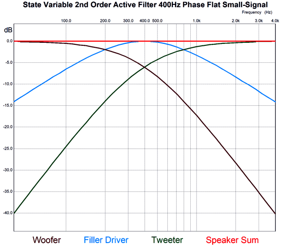
Here is the SPICE-generated graph.
Note that the filler driver must deliver a major chunk of the audio bandwidth. In short, a tiny midrange driver is probably not the best choice. I would look into using a fullrange driver instead. Look at the graph shown above and imagine that it is a three-way crossover with crossover frequencies of 200Hz and 800Hz; then, the need for a fullrange driver becomes more apparent. Of course, 400Hz is an amazingly low crossover frequency. With a higher frequency, say 2kHz, less is demanded of the filler driver, as most the energy is in the bass. But the higher the crossover frequency, the more difficult it will become for all three drivers to meld together due to the smaller wavelength.
Music Recommendation: Joshua Redman's Sun on Sand //JRB
Very few can imagine just how much hard work is required to make one of my posts. If you have any sort of inkling or intuition of what is involved, please think about supporting me at Patreon.
User Guides for GlassWare Software
For those of you who still have old computers running Windows XP (32-bit) or any other Windows 32-bit OS, I have setup the download availability of my old old standards: Tube CAD, SE Amp CAD, and Audio Gadgets. The downloads are at the GlassWare-Yahoo store and the price is only $9.95 for each program. http://glass-ware.stores.yahoo.net/adsoffromgla.html So many have asked that I had to do it. WARNING: THESE THREE PROGRAMS WILL NOT RUN UNDER VISTA 64-Bit or WINDOWS 7 & 8 & 10 or any other 64-bit OS. I do plan on remaking all of these programs into 64-bit versions, but it will be a huge ordeal, as programming requires vast chunks of noise-free time, something very rare with children running about. Ideally, I would love to come out with versions that run on iPads and Android-OS tablets.
//JRB |
|
I know that some readers wish to avoid Patreon, so here is a PayPal button instead. Thanks. John Broskie John Gives
Special Thanks to the Special 77 To all my patrons, all 77 of them, thank you all again. I want to especially thank
I am truly stunned and appreciative of their support. In addition I want to thank the following patrons:
All of your support makes a big difference. I would love to arrive at the point where creating my posts was my top priority of the day, not something that I have to steal time from other obligations to do. The more support I get, the higher up these posts move up in deserving attention.
Only $12.95 TCJ My-Stock DB
Version 2 Improvements *User definable Download for www.glass-ware.com |
||||||||||||||||
| www.tubecad.com Copyright © 1999-2022 GlassWare All Rights Reserved |
