| John Broskie's Guide to Tube Circuit Analysis & Design |
31 August 2022 Post Number 565
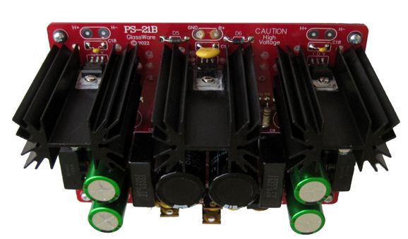
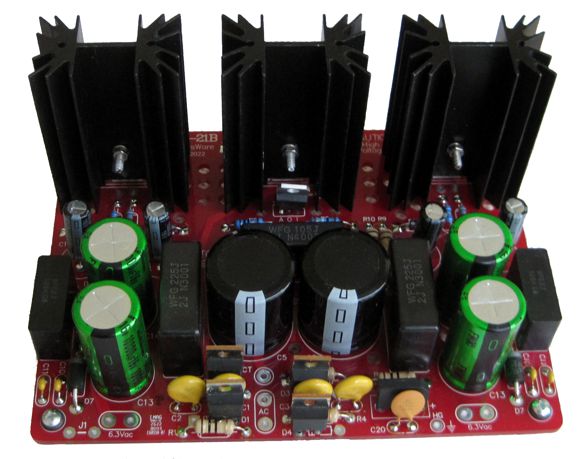
New PS-21B
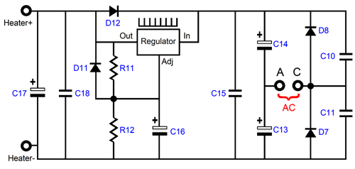
The rectifier circuit is still full-wave, so the ripple frequency will be twice the wall voltage frequency. The formula for potential output current is simple: Irect = Isec/3.6 For example, if the 6.3Vac secondary is rated for 3A of current flow, after the voltage-doubler circuit rectification, the maximum output current flow is 3/3.6 or 0.83A. This may not seem like much, but do not forget that the PS-21B holds two low-voltage regulators, one for each channel, so two 6SN7 or two 6CG7 or five 12AU7 tubes can be powered per regulator. Wait a minute, John, the 6SN7 is a 6.3V tube. Indeed it is, but two 6SN7 heaters can be placed in series and powered by a 12.6Vdc regulated power supply. Decades ago, all the tubes in a radio or TV were placed in series, which is why controlled-warm-up heaters were developed. You cannot imagine what a huge mental obstacle is the idea of using two 6.3V-heater tubes in series is for some. Some audiophiles ponder whether the Casimir Effect's alteration of the vacuum-expectation value of the energy of the second-quantized electromagnetic field might explain why tubes sound so sweet, but cannot understand how two or four 6.3V tubes could be used with a 12.6Vdc regulated power supply.
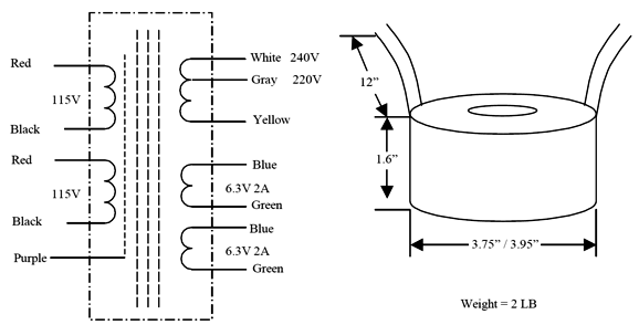
By the way, with the exception of tube-based power amplifiers, most tube-based audio gear does not require all that much B+ current flow. For example, an Aikido line-stage amplifier holding four 12AU7 tubes might only draw 20mA total. Even with a raw B+ voltage of 330Vdc, the dissipation is only 6.6W, excluding the heater dissipation (another 11W or so). For such a 12AU7-based line-stage amplifier, a 50VA power transformer would prove ideal, such as the AnTek AS-05T240 50VA 220Vac/240Vac toroid is a good candidate. The transformer holds three secondaries: a two-tap 220Vac and 240Vac, and two 6.3Vac @ 2A heater secondaries.
According to the formula, Irect = Isec/3.6, each heater winding can deliver only 0.56A of output current from the voltage-doubler circuit and regulator. Is that strictly true? Maybe not. Since we only draw 20mA from the high-voltage secondary (the two in parallel), the peak current draw is 1.8 times greater due to the rectification, so 36mA is demanded from the high-voltage secondary. Where does the extra potential 64mA of current go? Well, it could go to power the heater regulators. In other words, we could easily 3A from each 6.3Vac secondary in this example without exceeding the 50VA rating of transformer; this means that we can probably get an easy 800mA of DC current from each regulator. By the way, all the AnTek power transformers assume a 115Vac or 230Vac wall voltage. Well, where I live, the wall voltage never drops below 120Vac. Thus, I would use the 220Vac tap rather than the 240Vac, as the actual secondary voltages would be 230Vac and 250Vac. On the other hand, if your wall voltage is closer to 110Vac, then the nominally 240Vac tap is the one to use. Okay, having just said that, it's time to backtrack a bit. I never like to get near a power transformer's VA limit, as an overly taxed power transformer will get extra hot, buzz, and radiate hum. In other words, over specifying the power transformer is seldom a bad idea. This brings up a related topic: most solid-state power amplifiers hold power transformers that appear too wimpy. For example, a 100W per channel stereo power amplifier might hold a power transformer with a VA rating of only 300VA and a 70Vac CT secondary rated for only 4.3A—and yet the amplifier works just fine. How is that possible? Think about this: 100W into an 8-ohm load translates into 40Vpk and 5Apk. With both channels putting out 100W, the 200W of output power requires that the power transformer deliver 316W of power, but full-wave rectification of the secondary AC only yields 78% of the VA rating as useable output power, which in this example would be 236W. In other words, the power transformer falls short of the needed VA rating by 80VA, yet the power amplifier works just fine. The paradox is resolved when we realize that the power amplifier is meant to amplify music signals, not steady sinewaves at full output, something that a shaker-table amplifier might be required to do. Music, if it is at all interesting, exhibits a wide dynamic range. Yes, crescendos can thunder, but they are relatively brief. The actual average power output the 100W amplifier must deliver at "full output" is probably closer to 20W with classical music and 40W with grunge or droning synthesizer music. In contrast, a phono preamp or line-stage amplifier or active crossover will draw a steady current, so no dynamic fudging is allowed.
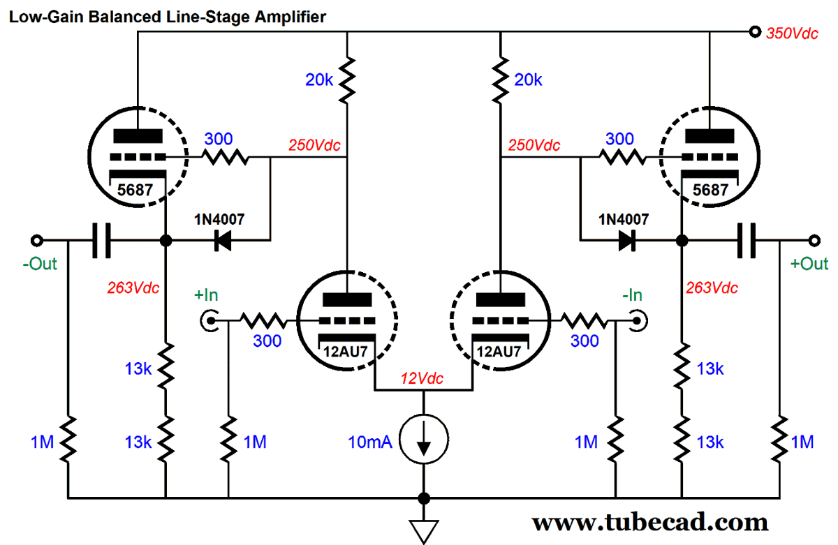
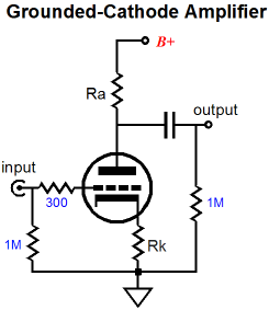
Here is a question: why offer two low-voltage regulators, not one? Over the decades, yes decades, I have been told that giving each channel its own isolated heater power supply produces better sound. Well, I finally got around to giving this proclamation a test about five years ago. It did sound better, not gobs better, but slightly better. What I found was that that if the cathode resistors were bypassed, most of the sonic benefit diminished. In contrast, with unbypassed cathode resistors, the improvement was noticeable. Do not forget that the heater element is separated from the cathode by the thinnest insulation imaginable, which means that heater element and cathode are joined by a relatively high capacitance. With a bypassed cathode resistor in a grounded-cathode amplifier, the cathode is effectively shorted to ground in AC terms; but without the cathode resistor bypass capacitor, the cathode can act as the grounded-cathode amplifier's non-inverting input. Of course, we can do many other things with two separate low-voltage regulated power supplies. For example, one could be used to power all the heaters, while the other is used to power a solid-state headphone amplifier or power buffer or external DAC. Or, in some tube circuits, some cathodes are at much higher voltages than the other cathodes, so one heater power supply cannot bridge the differential. In this case, giving the top tubes their own floating power supply makes the most sense. Here is just such a circuit.
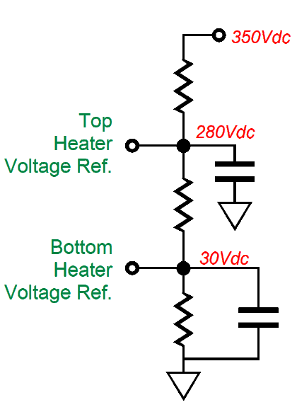
This is a simple balanced line-stage amplifier with a differential amplifier input stage and cathode follower output stages. The problem is that there's a 250Vdc voltage differential between the bottom tube's cathodes and the top tube's cathodes. This is too much to just split the difference at 125Vdc. Instead, the top and bottom tubes get their own regulated heater power supply. Note that that we should voltage reference the power supplies to some voltage slightly high than the cathode voltage for the best results.
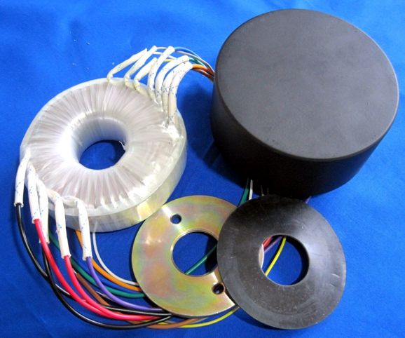
In conclusion, I designed the new PS-21B to exploit the great power transformers from AnTek. I use them all the time. I particularly like that they hold an electrostatic screen that when grounded shields the secondary from the primary, thereby furthering the isolation and noise reduction. In addition, AnTek sells nice-looking steel cans to house the toroids. The steel case for the 100VA transformers cost only $38.50 and looks great.
The new PS-21B power supply is available now at the GlassWare web-store.
A Folded Dipole
No doubt, some readers were irked by the shotgun wedding of a dipole and an acoustic-suspension-load subwoofer. They would prefer a dipole subwoofer. Dipole subwoofers are made, but they are very rare, as most subwoofers either employ sealed or ported boxes. The huge problem a dipole subwoofer faces is that deep bass frequencies are huge, which require equally huge baffles to prevent low-frequency cancelation. The wavelength of a 40Hz sinewave is 28 feet (8.3 meters). Well, what if we folded a dipole, so the dipole would visually appear smaller but would still provide a sufficiently acoustically long path to allow for some bass reproduction? Sadly, there have been a few modifications to the standard flat dipole baffle. My idea is that we could easily halve the dipole's width by applying folds at the left and right sides.
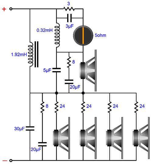
Four woofers are arranged in series-parallel to maintain the single-driver impedance for the four. In other words, if we use 4-ohm drivers, we get a 4-ohm load; 8-ohm drivers, 8-ohms. We also gain +6dB in SPL, as we enjoy a fourfold increase in radiating surface area, which yields a 12dB boost in SPL, but we also incur a -6dB decrease in SPL due to each woofer only seeing halve the signal, which makes for the +6dB increase in SPL. Well, my step will confuse many, as I am willing to throw away the 6dB increase. Why? Very few woofers were designed for use in a dipole, as most woofers are expected to be used in a sealed or ported box, which require lower Qs. A woofer's Qts is a measure of its internal dampening, both mechanical and electrical, with a Q of 0.5 called "critically damped." In a dipole, a Q of 0.5 or less will sound thin, as a Q of 0.5 results in the output being down by -6dB at resonance. Typical woofers exhibit a Qts of 0.25 to 0.4, which will sound threadbare in the deep bass. Thus, most planar dipoles use weakly damped woofers (or diaphragms) with Qs above 1 to undo the bass loss due to the narrow panel width. The usual workaround is to use a musical-instrument woofer, which usually present much higher Qs than hi-fi woofers. The problem with this workaround is that musical-instrument woofers usually offer too high a resonate frequency and too limited linear cone excursions. My workaround is to place a large-valued resistor in series with each HiFi woofer to purposely undo the electrical damping (Qes), so the woofer's Qts rises. In this example, each 8-ohm woofer would get its own 24-ohm power resistor. From post 396, see the same idea:
Let's do the math. Since each woofer only sees one quarter of the signal, its output is down -12dB. But as we gain 12dB due to four woofers being used, thus we end with a wash, i.e. no change in SPL. We do, however, get a much fuller bass response. How much? It depends on the woofer's specifications. We can use the formulas from post 396: Qes (new) = Qes*(R+RDC) / RDC Where Qes electrical part of woofers Q-Factor, and R is the added resistance in series with the woofer. To arrive at the new Qts (total Q) we must place the existing Qms (mechanical Q) in parallel with the new Qes. Here is an example with the Peerless 830990 6.5-inch glass-fiber composite woofer:
After placing a 24-ohm power resistor in series, we get:
Note that the resonant frequency and Qms remains unaltered. The resulting Q of 1.27 will create a peaking of 2.1dB at the resonant frequency, which is what we want. Perhaps it is more than we want. In that case, we could use three woofers, each with 16-ohm power resistor in series, as that would result in only 0.4dB of peaking.
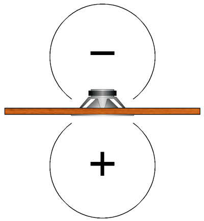
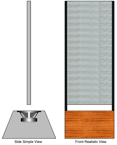
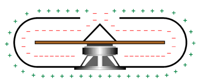
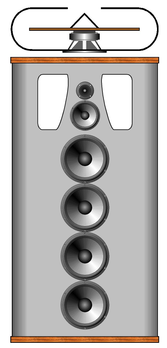
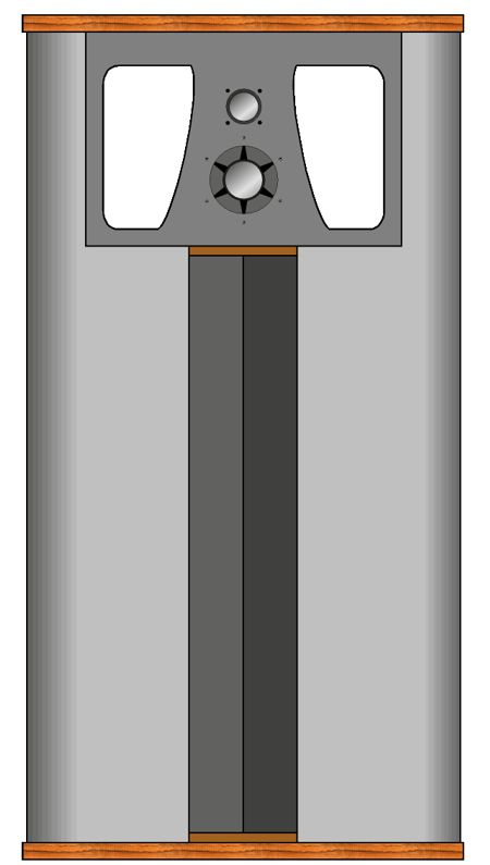
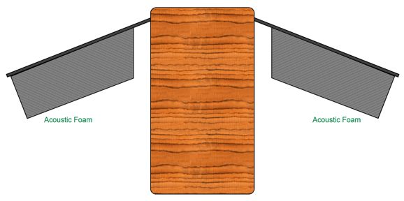
This view from above shows the output from the woofer's front traveling around the folded dipole and meeting the out-of-phase output from the woofer's rear. Note the path taken by the output from the woofer's front is longer than that taken by the output from the woofer's rear. This is why oval race tracks have staggered starting positions, as the inner track is far shorter than the outer track. The workaround is to add stuffing material to the inside of the folded dipole, as this will slow down the speed of sound inside the folded dipole. By how much? A good guess is not as much as we would like. I have seen high reports of a 50% reduction in speed to lows of only a few percent. A lot depends on how much stuffing is used and what type is used. In a folded dipole, I would expect to use light stuffing. What is the dipole made of? I would love to use aluminum sheet metal, which could easily be formed, sheared, drilled, and punched. Internally, plain old MDF wood panels could be used. Here is a rough idea of what I would love build.
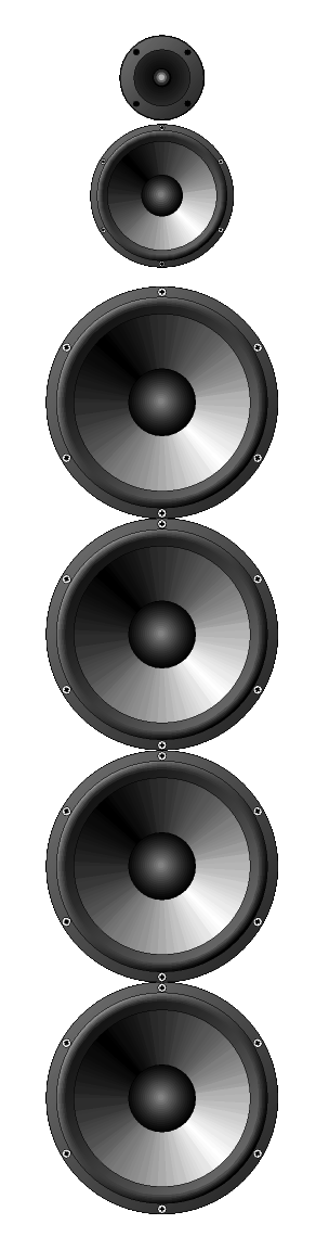
The midrange and tweeter get a far narrower dipole, while the four woofers get the folded-dipole treatment. In fact, we could bend the sheet metal in between the midrange and tweeter, so as to bring the tweeter into time alignment with the midrange. The back view shows the sound exit.
Screws could be used to hold the enclosure together, but perhaps only glue is needed; especially if many internal bracing horizontal pieces are employed, as the increased gluing surface could only help.
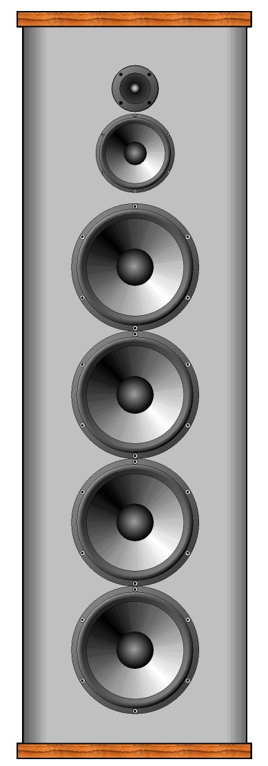
Another idea that has welded itself in my mind for decades is that of a folding-dipole loudspeaker, which could be listened to in either its folded or unfolded position.
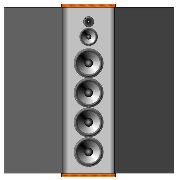
When folded, the loudspeaker looks like many other conventional speakers and functions more like a short transmission-line loudspeaker. When unfurled, however, the baffle width increases dramatically.
Having the deep enclosure structure will make the dipole much more imprevious to rocking, which is a much bigger problem than most imagine.
Topic for Next Post Well, this will be one of the topics in my next post. In the mean time, here is a sample circuit.
Note that the triode on the left is configured as a grounded-grid amplifier, so its input is its cathode, not its grid. The grounded-grid amplifier, unlike the grounded-cathode amplifier, does no invert the input signal phase at its output. The solid-state amplifier below it does invert the signal phase. The entire circuit realizes a gain of 1:100 (+40dB). It is intended to be the input stage of a two-gain-stage phono preamp for low-output moving-coil cartridges. The will be more to come.
Music Recommendation: Samara Joy
//JRB
Did you enjoy my post? Do you want to see me make it to post 1,000? If so, think about supporting me at Patreon.
User Guides for GlassWare Software
For those of you who still have old computers running Windows XP (32-bit) or any other Windows 32-bit OS, I have setup the download availability of my old old standards: Tube CAD, SE Amp CAD, and Audio Gadgets. The downloads are at the GlassWare-Yahoo store and the price is only $9.95 for each program. http://glass-ware.stores.yahoo.net/adsoffromgla.html So many have asked that I had to do it. WARNING: THESE THREE PROGRAMS WILL NOT RUN UNDER VISTA 64-Bit or WINDOWS 7, 8, and 10 if the OS is not 32-bit or if it is a 64-bit OS. I do plan on remaking all of these programs into 64-bit versions, but it will be a huge ordeal, as programming requires vast chunks of noise-free time, something very rare with children running about. Ideally, I would love to come out with versions that run on iPads and Android-OS tablets.
|
I know that some readers wish to avoid Patreon, so here is a PayPal button instead. Thanks.
John Broskie
John Gives
Special Thanks to the Special 77 To all my patrons, all 77 of them, thank you all again. I want to especially thank
All of your support makes a big difference. I would love to arrive at the point where creating my posts was my top priority of the day, not something that I have to steal time from other obligations to do. The more support I get, the higher up these posts move up in deserving attention.
If you have been reading my posts, you know that my lifetime goal is reaching post number one thousand. I have 444 more to go. My second goal was to gather 1,000 patrons. Well, that no longer seems possible to me, so I will shoot for a mighty 100 instead. Thus, I have just 23 patrons to go. Help me get there. Thanks.
Support the Tube CAD Journal & get an extremely powerful push-pull tube-amplifier simulator for TCJ Push-Pull Calculator
TCJ PPC Version 2 Improvements Rebuilt simulation engine *User definable
Download or CD ROM For more information, please visit our Web site : To purchase, please visit our Yahoo Store: |
|||


| www.tubecad.com Copyright © 1999-2021 GlassWare All Rights Reserved |