| John Broskie's Guide to Tube Circuit Analysis & Design |
28 February 2023 Post Number 577
Here I Go Again
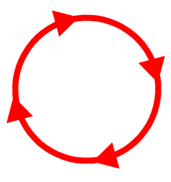
A circle of current flow is precisely why we call it, a circuit, i.e. a complete route that an electric current can flow around, a never-ending looped pathway for charge carriers, a closed path in which electrons move to produce electric currents, a complete circular path that electricity flows through, a closed path that consists of circuit components in which electrons from a voltage or current source can flow, a closed loop network which provides a return path for the flow of current…all these definitions were taken from dictionaries. My counter response was to ask if it was possible to adjust the idle current in a circlotron output-stage up or down. I was told that it—obviously—could be altered. Next, I asked: since if the current can be reduced with no departure from class-A operation, why not reduce it to near zero current flow, say 1mA, thereby creating the world's first room-temperature class-A amplifier? I was told that it could be done, as it was circle of current after all. Next, I asked if under that crazy light idle current flow would any of the output tubes ever completely cease conducting, resulting in an affirmative answer. I went on to point out that wasn’t odd the key defining feature of class-A operation is that the output devices never stop conducting, but the output tubes in this circlotron certainly would? The conversation usually ended at this point, but a few steadfast readers wanted to hold on to the "class-A amplifier" status. Strange behavior, but really not all that strange; royal and honorific titles once bestowed are hard to renounce. The following is a quote from my 1999 Tube CAD Journal section titled Angry E-mail: Class-A Advertising.
Indeed, some wish to fool you, but a few of us end up fooling ourselves. Many tube-loving musicians will happily inform you that all tube-based power amplifiers that employ a cathode-bias resistor on the output stage are by that very fact class-A amplifiers. But then, musicians are known to smoke stronger weed than the average calmer, more timid, and less fanciful audiophile.
One audiophile false belief, however, keeps coming up—namely, that two single-ended amplifiers can be arranged in anti-phase and not transform into a push-pull amplifier. They can't. Yet, I see this error being stated all the time, especially in audio magazines. Speaking of audio magazines, over dinner an editor of an audio magazine once told me that he was flooded with offers by want-to-be audio reviewers. He went on to say that most were, oddly enough, lawyers. Interesting. I am reminded of Ambrose Bierce's definition of a lawyer: "One skilled in circumvention of the law." One problem is that "single-ended" and "push-pull" are poorly named. How I wish that single-ended amplifiers had instead been called single-phase amplifiers; push-pull amplifiers, in contrast, bi-phase or di-phase or anti-phase or dual-phase or, just, two-phase amplifiers. Damn it, John, what does phase have to do with single-ended and push-pull amplifiers? Basically, everything. Let's start at the beginning with a super simple single-ended output stage.
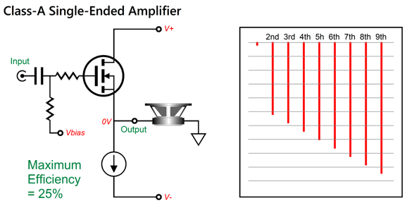
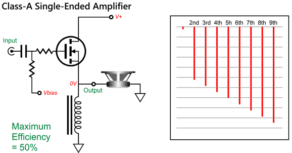
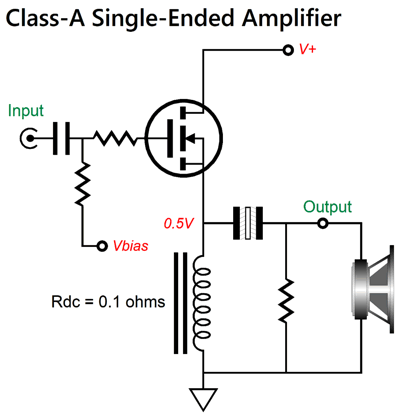
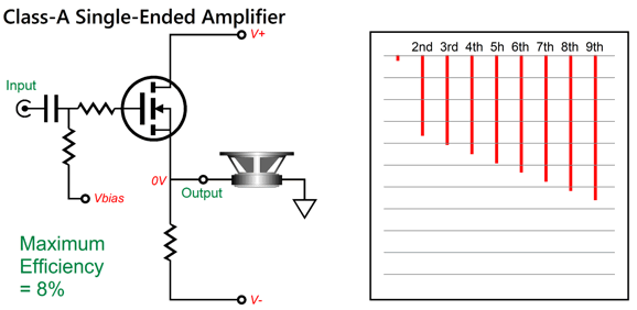
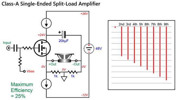
I used an N-MOSFET loaded by a constant-current source, but I could have used either a bipolar-transistor or triode. The principle remains the same: the output voltage follows the input voltage; as the output device draws less current, the output voltage swings negatively, having been tugged down in voltage by the constant-current source; and as the device draws more current, the output voltage climbs positively. When the output device swings positive it must continue to deliver current into the constant-current source and into the external load resistance. The math is simple: the output stage must idle at the desired peak output current swing. For example, if 100W is desired into an 8-ohm load, then the peak current swing into the load will be 5A, and thus so, too, must be the idle current. The 5A against the 8 ohms of resistance equals a peak voltage drop of 40V, so the bipolar power-supply rail voltages must be at least +/-40Vdc. (An actual single-ended amplifier would require closer to +/-45Vdc.) The maximum theoretical efficiency, which assumes perfect output devices and constant-current sources, is 25%. For example, to get 25W of output power requires an idle dissipation of 100W, which includes only the output stage, not the tube's heater elements or input stage and power-indicator light and any power-supply losses. Actual single-ended output stages with constant-current source loading always deliver less than 25%, as perfect output devices and constant-current sources do not exist. This is an energy-expensive arrangement, true enough, but the resulting array of frequency harmonics follows a lovely bottom-ward decline, which the ear find pleasing as it mimics nature. We can, however, double the maximum theoretical efficiency, bringing it up to 50%, by replacing the constant-current source with an inductor.
The dissipation is halved and the same sweet cascade of harmonics results. The schematic assumes a perfect inductor that neither displaces voltage nor dissipates any heat. Sadly, real inductors are made from wire and, often, iron cores. For example, if the inductor's Rdc (DC resistance) equals a tiny 0.1 ohms, and if the MOSFET draws 5A at idle, the inductor will see a voltage drop of 0.5V (or 500mV), way too much DC offset for normal loudspeakers. The workaround is to use a large-valued but low-voltage output coupling capacitor.
By itself, the inductor offers the loudspeaker great protection in the case of a circuit fault, but the output capacitor offers additional protection.
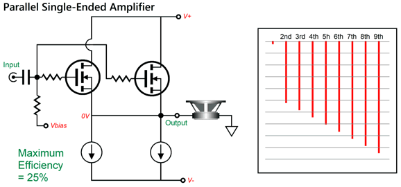
If you do not mind the high electric bill (and plaintively accusative letters from the electric company), you can replace the constant-current source with a resistor: a power resistor, massively big, usually shrouded in ribbed-aluminum casing. The distortion rises and the maximum theoretical efficiency plummets to below 9%. In the search for greater power output, a commonly taken approach is to add parallel output devices.
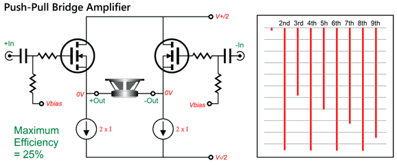
The same glorious single-ended cascade of harmonics results, while we get more power output. So far, so good. What if we split the parallel single-ended output stage and create a bridge output stage? Surely, we would construct a single-ended bridge amplifier. Still single-ended. Still class-A. Right? WRONG!
What we have produced is a class-A push-pull amplifier, not a single-ended one, which is revealed by the analysis of the Fourier graph showing the resulting harmonics. The single-ended cascade is gone, having been replaced by the push-pull's jagged saw-tooth cascade, wherein the euphonic even order harmonics are nulled, leaving prominent the harsh odd order harmonics. Why? What went wrong?
The both output devices no longer operate in current phase. A pair of anti-phase input signals drive the two MOSFETs, so as one conducts more, the other conducts less. It doesn't matter whether the output devices are tubes or transistors or MOSFETs or FETs; the more closely matched the devices, the deeper the even-order null will be at full output. Perhaps, you have read that the circlotron is basically two single-ended amplifiers in parallel. It is not. Deconstructed, the circlotron is a push-pull arrangement of two split-load phase splitters run in tandem and in anti-current phase. Single-ended means single current phase. We can, however, create a single-ended circlotron.
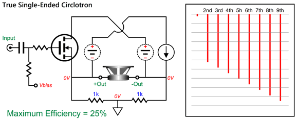
This is a circlotron, as it contains all the defining features: the split-load referencing of the signal ground still applies, the circuit yields a gain of 2, and two floating power supplies are used. Thus, this output stage qualifies as a circlotron. In addition, the output impedance is not as low as it would be with source a follower arrangement, as we must pay for the gain with an increased output impedance. Most importantly, the single-ended cascade of harmonics obtains, but at the cost of only 25% efficiency.
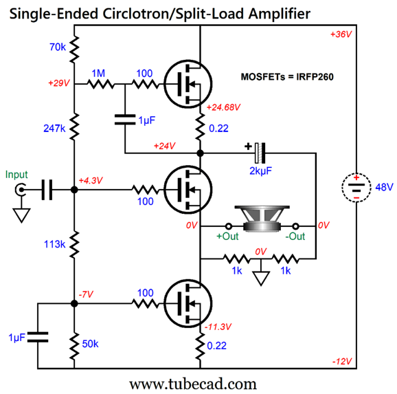
Here is another circlotron that reveals it split-load-phase-splitter DNA.
The huge problem is that placing two constant-current sources in the same current path can cause huge hassles, unlike using two inductors in place of the constant-current sources. The workaround is to use at least one compliant constant-current sources.
I ran SPICE simulations on this circuit, and the results were reassuring.
In spite of the balanced output, we still see the beloved single-ended cascade. (By the way, if I were to actually build this amplifier, I would double up o the center MOSFET, as it must dissipate twice the heat as the botto or top MOSFET does.) Okay, let's now compare these circuits to the conventional circlotron.
The assumption here is that the idle current runs hot enough to guarantee class-A amplification at full output. In other words, none of the output devices ever completely ceases conducting. Sadly, no single-ended cascade of harmonics results. The audio-magazine review and the audio-company brochure might state that it is a single-ended amplifier, possibly a single-ended amplifier run in parallel, but the Fourier graph says otherwise. You might tell your daughter that she is a princess, but with no kingdom for her to rule, no sovereign progenitor, the title is largely devoid of semantic content. Let's look into a conventional totem-pole output stage that uses identical output devices.
The output MOSFETs run in current anti-phase, which allows the output to swing up and down in voltage. If they ran in current phase, the output would stick at 0V, as perfect tie would result, much in the same way that two perfectly equally strong men cannot win or lose an arm-wrestling match. By the way, we can convert this circuit into a circlotron circuit, albeit a non-conventional circlotron, by placing the signal reference mid the output load.
I showed this variation twenty years ago in my article, Cars, Planes, and Circlotron. It functions identically to the conventional circlotron, delivering the same distortion, output impedance, and gain of 2. (We could, if we wished to prevent confusion, call the conventional circlotron the "horizontal circlotron" and this variation the "vertical circlotron.") The big difference between this circlotron and the totem-pole output stage, other than where the signal reference falls (i.e. ground), is the difference in input signal amplitudes.
The conventional totem-pole output stage requires dissimilar amplitudes of anti-phase input signals, as the top MOSFET's source follows the output voltage swings, while the bottom MOSFET's source is effectively grounded. In contrast, vertical circlotron's two MOSFETs see the same amplitudes of anti-phase input signals, which are roughly half of what the output voltage swing realizes across the loudspeaker. Do not forget the circlotron's gain of 2. Can we transform this vertical circlotron into a single-ended amplifier? We could, but we must reduce it to a single current phase.
The bottom MOSFET is gone, replaced by the constant-current source. (The constant-current source could be made from a MOSFET and NPN transistor.) Therefore, strict class-A idle current is needed, as class-AB or class-B light idle current is no longer possible. But we do get the desirable single-ended cascade of harmonics, but at the cost of halving the efficiency. Before leaving the topic of circlotrons, let's look at another variation.
Looks crazy doesn't it, as it looks as if it would never work. It does. Let me redraw it for you.
It's the inverted and functionally identical version of the conventional circlotron. I made use of this variation in post 137 when I created the following circuit.
The two triodes form a bastode (cascode-like) circuits with the P-MOSFETs below them. I recommend that you read the post, as you will then encounter this super interesting variation.
This hybrid circlotron employs both AC and DC negative feedback. Sadly, we still get the push-pull's signature jagged saw-tooth cascade, with its nulled even-order harmonics.
Now, we move onto tube-based single-ended amplifiers. We begin with the super-simple single-triode single-ended amplifier.
Only one current phase appears in this amplifier and the resulting single-ended cascade bears this out. The big problem is that is difficult to get big watts with one output tube, so some double up on the output tubes.
As both triodes see the same input signal, they run in current phase. What if we took two complete single-ended amplifiers and paralleled the output transformer's secondaries?
Once again, both triodes see the same input signal, so they run in current phase and we get the single-ended cascade. As far as each amplifier is concerned, the loudspeaker's impedance has been doubled. In other words, if an 8-ohm speaker is driven, each amplifier thinks it is driving a 16-ohm speaker. What if we flip the phase on one of the secondaries and drive the triodes in anti-phase?
We would still double the power delivery, but we would also greatly improve the PSRR, assuming the same B+ voltage power supply was used for both amplifiers, as the ripple leakage would be in anti-phase between the secondaries, thereby creating a ripple null across the loudspeaker. While the improved PSRR is welcome, the elimination of the desirable single-ended cascade of harmonics isn't. The even-order harmonics, like the ripple, becomes nulled. By the way, we can place the two secondaries in series rather than in parallel.
As far as each amplifier is concerned, the loudspeaker's impedance has been halved. In other words, if an 8-ohm speaker is driven, each amplifier thinks it is driving a 4-ohm speaker. We can also run two single-ended amplifiers with their secondaries connected in series.
Since both amplifiers run in current phase, we get the single-ended cascade of harmonics. (See posts 141 and 524 for more details on multiple-secondary arrangements.)
What makes a king a true king and not just the owner of a royal title is his possessing a kingdom and loyal subjects. What makes an output stage single-ended (and not just some advertising-copy adjective) is single-phase current conduction and the lovely single-ended cascade of harmonics. By the way, "steered" constant-current sources introduce an anti-phase operation and create push-pull operation as a result. See post 466 for more details.
Robert Koda Takumi K-160 Amplifier
(Koch changed his last name to Koda.) It wasn't the mention of "pure class-A," but the inclusion of "a double single-ended power architecture" and "all the sublime qualities of a single-ended amplifier" that caught my attention, which was soon followed by noting the £80,000 price tag, which translates into, last time I looked, $96,348. Mercy, imagine if you wished to run a quadraphonic or a tri-amp system. Since this amplifier is so new, I could find little additional information online. I did, however, find some material on the amplifier's predecessor, the Koda Takumi K70, a three-chassis stereo amplifier. You have to admire the aesthetics; very Japanese. The center chassis holds the power supply for the two bracketing mono-bloc power amplifiers. The amplifiers are hybrid affairs with a pair of input tubes, Raytheon 5842 (AKA WE417), and 34 Toshiba 2SC5200 output transistors.
(While on the topic of the WE417, here is a quick aside. I once owned an egg-crate grid of either 10 by 10 or 12 by 12 slots, each filled with an NOS WE417 tube, which would be worth either $17,500 or $25,200 today. What happened to them? A sad story, alas. Thirty years ago, I was at a Silicon-Valley tube-club meeting and a fellow I never met before told me that he had built a phono stage based on the WE417 as the input tube and that it was painfully microphonic. Since the WE417 offers a screaming transconductance of 27mA/V, this isn't surprising. I told him that I owned a bunch of those tubes and offered him the chance to pick out the two quietest WE417s for free. He arrived at my home and I gave him the whole lot of WE417s to take home and test at his leisure. I never heard from him again. Mind you, I didn't search him out, as I pretty much forgot about the tubes until a friend, a decade later, mentioned how expensive they had become. I hope that he used the tubes wisely, say as a down payment on a BMW or house.) Okay, back to the Koda Takumi K70 amplifiers, we read in audio-magazine reviews that the amplifiers are balanced (or bridged) single-ended, negative-feedback-free affairs with a huge DC offset of 16.5Vdc at the two output terminals, so a danger of toasting a woofer exists when only one loudspeaker lead is attached and the other touches the chassis. Workarounds would have been to cover that section below the output terminals with a thin plastic overly or, what is a far better idea, to add a negative power-supply rail to the amplifier. Actually, a third and safe option would be to float the power supply and add a two-resistor voltage divider to set the signal reference mid-output, ala the circlotron. In fact, when I saw the two large electrolytic capacitors at the center of the amplifier chassis, I assumed the amplifiers were circlotrons. They aren't, which was revealed in photo showing the two capacitors wired in parallel. I could not find a schematic for the amplifier, but this is my guess of what the topology looks like:
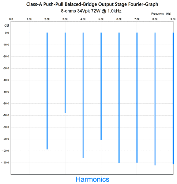
Only two stages are used, input and output, both balanced. In the reviews, I read that Mr. Koda relies entirely in NPN transistors, completely eschewing PNP types, so neither a diamond structure nor a compound arrangement could have been used. (Perhaps, he used a triple-Darlington NPN emitter follower to unload further the tube-based input stage. No negative feedback loop is employed, so the low distortion and low output impedance result from the heavy class-A idle current flow and the emitter follower's inherently low distortion. Here is the SPICE-generated graph for just the output stage at full output.
Sorry, but in spite of the CCS-loading, I do not see the single-ended cascade of harmonics on display; rather, I see the typical push-pull cascade. Assuming that my guess is right, what would I do differently? To start with, I would use a bipolar power supply (+/-18Vdc), so the potentially dangerous DC offset could be eliminated. Next, I would add two DC servos (something I understand Mr. Koda disdains) to ensure the smallest DC offset possible. In addition, adding the DC servos would allow for easy adjustments of the idle current. Let's say you just want some pleasant background music, not thundering audiophile demo levels, so a multi-stage idle switch would come in handy. The DC servos would ease the decline in idle current, while maintaining a low DC offset. I would certainly look into replacing the 5842 tubes with 6DJ8s in a differential cascode configuration, where the top devices might be NPN transistors. Dear God, why? Balance, my friend, balance.
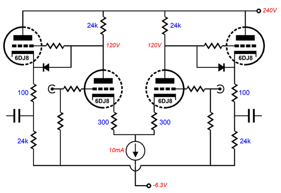
The odds of buying two WE417 or 5842 single-triode tubes that match each other are laughably slim. The tube industry standard was to match the twin-triode tubes (internally) that were deemed suitable for audio or test measurement work, such as the 6SN7, 6DJ8, 12AU7... to 5%. (A standout matched twin-triode tube is the 6SU7, which was a tightly matched 6SL7 intended for use in the frontend of an oscilloscope.) Twin-triode tubes designed and destined for other applications, such as the 6BX7, were allowed far worse internal matching, say only a 20% match. With single-triode tubes, it is up to you to do the matching. In addition, it's been at least half a century since the last 5842 and WE417 tubes were made. Just how many do you think remain? In addition, surely all the good ones were culled long ago. In contrast, fine 6DJ8s are being made today. What if the 6DJ8 cannot develop sufficient gain to drive the bridged output stage? My guess is that it cannot do so due to the relatively low-impedance load presented by the output stage, but placing three 6DJ8s in parallel certainly could—as their combined transconductance would exceed that of the WE417. The real problem isn't creating gain, but driving a low-impedance load. If we add two cathode followers, that problem disappears.
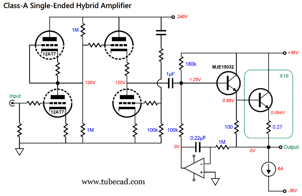
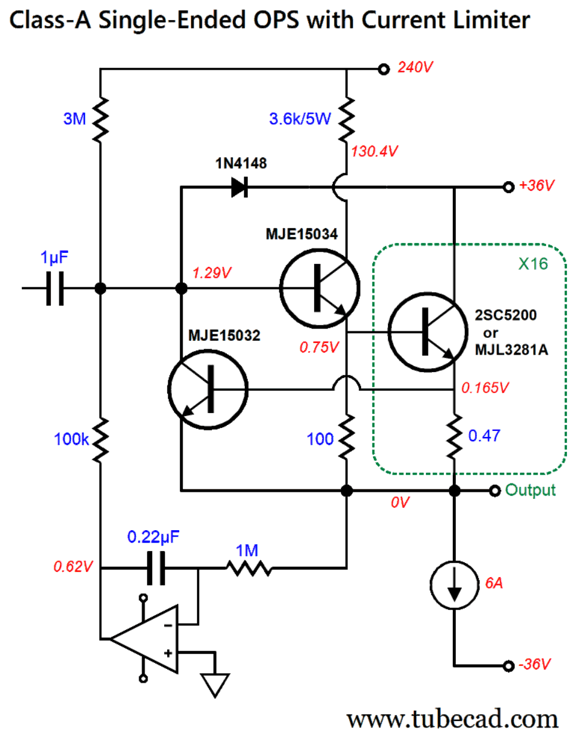
The long-tailed differential input stage now has a close-to-nonexistent load to drive. In fact, now that it is freed from driving the output stage directly, the 6DJ8 develops a bit too much gain, so the 300-ohm cathode resistors were added, which both reduce gain and distortion. The cathode follower tube should get its own floating power supply referenced to +140Vdc, while the input tube's heater can be powered by the -6.3 power-supply rail. But I would truly love to do is lose the balanced-bridge push-pull output stage, replacing it with a true single-ended one. (If that last sentence made no sense, read the section above.) To get 70W of single-ended output into an 8-ohm load requires peak voltage swings of 33.5Vpk, so a bipolar power supply of at least +/-36Vdc would be needed. We would place 16 output transistors in parallel and load them with a single 6A constant-current source. Why 6A? If we hope to deliver 70W into a 4-ohm loudspeaker, then we must be able to deliver 23.7Vpk and 5.92Apk into the load. Note that the idle dissipation is a wash between this proposed single-ended output stage and the balanced-bridge output stage, as both dissipate the same 432W at idle. Each transistor will dissipate 13.5W at idle. In other words, the same parts are used, but are differently arranged. Since I want to eliminate the push-pull balanced output, there is no need to stick to the differential input stage. (If a balanced signal source were used, then an input signal transformer could be added.) What input stage could we use instead? I would start with an Aikido gain stage that held a 12AT7/ECC81 input tube and either a 6DJ8 or ECC99 or 5687 output tube.
The 12AT7 input tube requires a little over 1Vpk of input signal to develop 34V of peak output signal. (Another possible input tube would be the 5751 twin-triode tube that offers an amplification factor of 70. Some were made in a low-microphonic style, with stacked mica wafers and a tension clip.) If a 6DJ8 were used in the Aikido cathode-follower position, then an idle current of 5mA would be appropriate; with a 6H30 or ECC99 or 5687, 10mA. Of course, I can think of many more input stage topologies, but it is the output stage that is more important. The output stage runs off a +/-36Vdc bipolar power supply. The DC servo eliminates any DC offset. Sixteen output transistors and their emitter resistors are placed in parallel. Although this sounds extravagant, bear in mind that a single KT88 tube would cost more. The real source of the high cost is the power transformer and heatsinks required. Moreover, with sixteen output transistors, we need not fear beta droop. Furthermore, sixteen output transistors allow us to spread the heat more evenly across the long heatsink. We could get extra fancy. For example, we could add some current-limiting circuitry to protect the output transistor in the event of a shorted output.
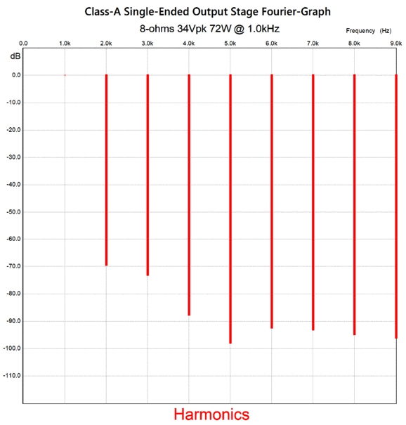
The MJE15032 imposes about a 1.5A current limit per output transistor, which is still a huge amount of current flow, but still far lower than it would be without the protection circuitry. The driver emitter follower uses an MJE15034 high-voltage transistor and it runs off the 240V B+ voltage. Why? The assumption here is that the high-voltage rail would be regulated. The 3.6k collector resistor simply limits the transistor's collector voltage and its dissipation. The 1N4148 diode protects the output transistor from excessive base voltages. We want the DC servo's output voltage at idle to be as close to 0V as possible, as that would ensure the greatest potential output adjustment swings. This explains the 3M resistor and its attaching to the 240Vdc B+ voltage, not the 36Vdc power-supply rail. Here is the SPICE-generated graph of the SE output stage at full output.
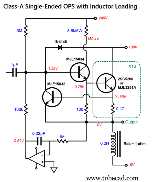
I love the strong 2nd and 4th and the greatly suppressed 5th harmonics. Bear in mind that all the same parts were used, but differently arranged, which allowed us to go from two-phase AC operation to single-phase. (SPICE showed an output impedance of 0.075 ohms—not bad for a negative-feedback-free output stage.) By the way, the single-ended output stage's efficiency could be greatly enhanced by replacing the constant-current source with a power inductor. We could then use a monopolar power supply with an output coupling capacitor or add a low-voltage negative power-supply rail. For example, if the inductor's Rdc were 1 ohm, then a negative power-supply rail would ensure 6A of idle current flow. Actually, we might not need much inductance, as the sixteen output transistors present such a low output impedance and sustain low-frequency notes are rare in most music, so we might get away with 100mH—or even less, say only 10mH. Jantzen Audio makes a 10mH 15-AWG air-core inductor with an Rdc of 1.2 ohms, which against 6A of current flow results in a voltage drop of 7.2V and a heat dissipation of 43.2W, a small fraction of what the constant-current source would dissipate. What about low-frequency extension? With the 1µF coupling capacitor and the 10mH inductor, the -3dB frequency was 2.6Hz in SPICE simulations. The low-inductance trick only works with typical music playback, however, not lab testing with sustained 20Hz sine-waves at peak output. The formula for minimum inductor size is the following: H = 1000 ·R/(2 ¶F) Where H is in millihenries; R, load resistance; and F, the low frequency cutoff. Plugging in 8 ohms and 20Hz, we get 63.7mH as the needed inductance, which means no air-core option, leaving us with only inductors with an air-gapped iron core.
Alas, power-supply chokes do not cut it, as the core alloy must be audio-grade; in other words, the same quality of iron as used in output transformers. On the other hand, if you are making amplifiers that cost more than the average car, you can go to the trouble of sourcing a high-qulatity inductor core, as the inductor would save you the cost (and weight) of constant-current source. Roughly, you would halve the heatsink and power supply heft—and, possibly, halve the price tag.
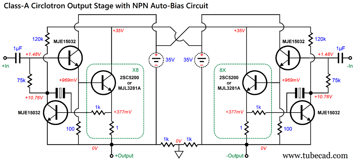
Circlotron to the Rescue We do not actually need the constant-current sources. While they save us from the hassle of setting and maintaining the idle current, they do nothing to improve the sonic performance of the amplifier. A bold statement, no? We could simply build a circlotron output stage that actually ran in strict class-A, with two banks of eight output transistors and standing idle current 3A per bank, a total of 6A. Why? Instantly we would halve not only the heat dissipation, but the heatsink size, the array of transistors used in making the constant-current sources, and the cost. But what about all the single-ended-sweet-sweet sonic goodness? It wasn't there in the first place, we just imagined that it was. By running half the output transistors in anti-current phase in the balanced-bridge output stage, we created a push-pull output stage. It may not look like one, but it is one nonetheless. The equivalent circlotron output stage offers the same distortion and harmonic structure, but at half the cost.
My "Broskie" influence is found in how the driver transistors (MJE15032) do not share the collector termination as the output transistors they drive. Why? We get bigger potential output swings this way, but at the cost of a small—and of zero consequence—DC offset. Are you sure, John, as 92mV seems like a big DC offset voltage? It would be, if this were not a balanced output stage. As long as both loudspeaker terminals see the same DC voltage, no functional difference exists between them, even if the shared voltage is 1kV. Of course, you might die if you touched it, but the loudspeaker drivers cannot see the 1kV voltage. Why does the DC offset occur at all? The driver transistors draw current through their bases, unlike vacuum tubes or MOSFETs. This small current flow against the two 1k resistors establish a small DC offset. The workaround is to contain all the current flows within the circlotron circuit.
Now, all the DC current flows are trapped between the two input coupling capacitors; thus, no DC offset. In other words, the driver transistor base current was not delivered from a power supply external to the circlotron output stage. We have seen the Blumlein garter-bias circuit here before, for example, in post 163. If one output drifts positively, that drift will cause the other output to follow, and vice versa. It is a simple form of self-balancing. The problem is that transistors, unlike tubes, are super sensitive to heat. The hotter they become, the more current they conduct. As you can readily see this creates a deadly positive-feedback loop. This why every transistor-based power amplifier must ensure that its bias-spreader circuit accurately tracks changes in heatsink temperature. The constant-current source loading sidestepped this problem by imposing a strict limit to current flow. In short, the Blumlein garter-bias circuit only works well in SPICE simulations, not reality. It would work well, however, with lateral MOSFETs. One workaround is to use DC servos to establish a fixed idle current flow, in spite of changes in heat.
This arrangement only works due to the class-A idle current. In other words, since none of the output transistors ever cutoff completely, the average voltage drop across the emitter resistor is held constant. This is never the case in a class-AB amplifier, as the output devices do cutoff completely. We can use this OpAmp-based circuit to both set the idle current and to eliminate a DC offset, but Mr. Koda can't, as the audio reviews point out that he eschews DC servos. I do not know if he dislikes servos in general or if he disdains OpAmps because they contain PNP transistors. One workaround that would also forswear PNP transistors is to use two NPN transistors in place of the OpAmps.
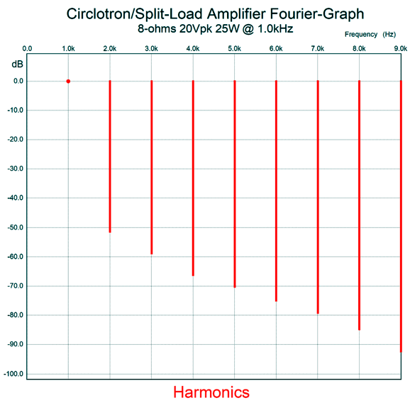
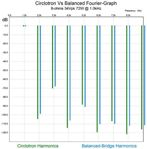
The NPN transistor's emitter-to-base voltage is used as a voltage reference to compare to the voltage drop across the emitter resistor. The non-polarized electrolytic capacitors are not marked in value, but anything over 47µF would work. (I would use 470µF/6.3V capacitors.) It is critical that the added NPN transistors not attach to the same heatsink that the output transistors attach. Indeed, these two transistors should be thermally tied together by mounting both on the same separate heatsink, one located away for the heat sources. Okay, let's return to the contest between dueling output stages. Years ago, and I mean many years ago, after I had discovered James W. Bongiorno's patent that used an auto-bias circuit on his version of the circlotron, I performed SPICE simulations on both these topologies: a balanced-bridge output stage with two constant-current sources and a circlotron with no constant-current source and half the idle current. Both were run in strict class-A operation. I used, however, power MOSFETs instead of NPN transistors. The SPICE-generated results were that the circlotron had a slightly lower THD and output impedance. Why the small difference? Possibly, the balanced-bridge output stage was further burdened by the constant-current sources or the MOSFET was pushed out of its sweet spot by the doubled current flow. In other words, output MOSFETs had to fight against not only the loudspeaker impedance but also the constant-current sources. In contrast, the circlotron only had to fight the loudspeaker impedance. Well, I decided to perform the shootout again, but with transistors in place of the MOSFETs. The results from SPICE simulations of full-output deliver into an 8-ohm load were interesting.
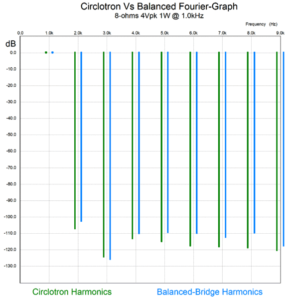
The circlotron wins at the 2nd, 3rd, 6th, 8th, and 9th harmonic, but loses at the 5th and 7th. Bear in mind that the differences are small. Here is an example of the rare distinction of there being so little difference. I doubt that even the most exalted and worthy audio reviewer could hear any difference between these two output stages. Also, keep in mind the circlotron idles at half the current of the balanced-bridge, which means half the heat and half the cost of power transformers, heatsinks, and electric bill. Well, that was at full output, but what about at 1W of output?
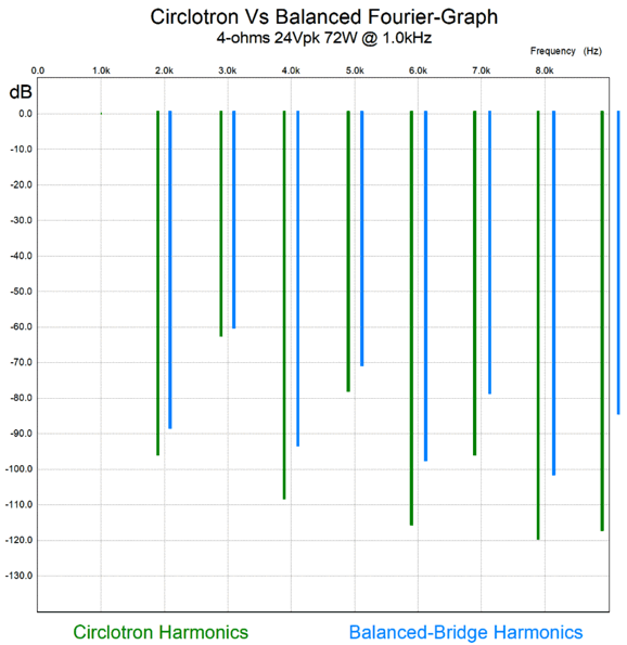
This time the circlotron version wins at all the harmonics but the 3rd, but only slightly. Still, there is no real difference. What about with a 4-ohm load? Well, things do get interesting now.
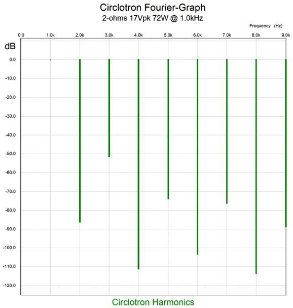
Now, the circlotron kicks butt big time, winning at all the harmonics—and killing it at the 6th, 7th, 8th, and 9th. What happened? The two constant-current-sources auto-bias feature in the balanced-bridge output stage imposes a strict current limit to both positive and negative output swings. (Yes, both positive and negative—and symmetrically. Think about it; it makes sense. In contrast, a typical tube-based single-ended amplifier can asymmetrically swing more positively than it can negatively.) With the 4-ohm load, however, we brush up to that current limit imposed by the two constant-current sources. In contrast, the circlotron sees no limit to its current flow other than its output devices melting down or blowing a fuse. How so? Once the circlotron exceeds its maximum class-A window of current swing, it enters class-AB mode. Remember, class-A operation is all about current flow. All class-AB amplifiers are also class-A amplifiers over a tiny output window of current flow. And all class-A amplifiers revert to class-AB amplifiers when driving too low a load impedance. Basically, once the output current swings exceed twice the idle current, the push-pull class-A amplifier ceases to be a class-A amplifier. Here are the results from the circlotron driving a 2-ohm load.
Not bad. Amazing, when we take in account the negative-feedback-free operation. I will not show you the equivalent graph for the balanced-bridge output stage; it wasn't pretty. Here are the current-flow relations in the output stage while driving the 2-ohm load.
In spite of the healthy 3A idle current, the output stage has broken out of the class-A window of current flow, thereby entering class-AB mode.
The Wrong Conclusion What then was the purpose behind this post? Increased clarity. Adding constant-current sources does not necessarily make a single-ended amplifier. Sometimes, seeing push-pull operation is difficult; for example, the circlotron, SRPP, White cathode follower, and SRCFPP. Post 366 is worth reading on this topic and on the topic of single-ended versus push-pull. Nonetheless, the distinction between single-ended and push-pull is sharp and well-defined. Let's keep it that way.
Patreon
Music Recommendation: Once again, Qobuz beats Amazon Music, as they offer the recording in glorious 24-bit, 88.2kHz high-res format.
//JRB
User Guides for GlassWare Software
For those of you who still have old computers running Windows XP (32-bit) or any other Windows 32-bit OS, I have setup the download availability of my old old standards: Tube CAD, SE Amp CAD, and Audio Gadgets. The downloads are at the GlassWare-Yahoo store and the price is only $9.95 for each program. http://glass-ware.stores.yahoo.net/adsoffromgla.html So many have asked that I had to do it. WARNING: THESE THREE PROGRAMS WILL NOT RUN UNDER VISTA 64-Bit or WINDOWS 7, 8, and 10 if the OS is not 32-bit or if the OS is 64-bit. I do plan on remaking all of these programs into 64-bit versions, but it will be a huge ordeal, as programming requires vast chunks of noise-free time, something very rare with children running about. Ideally, I would love to come out with versions that run on iPads and Android-OS tablets.
|
I know that some readers wish to avoid Patreon, so here is a PayPal donate button instead. Thanks. John Broskie
John Gives
Special Thanks to the Special 80 To all my patrons, all 80 of them, thank you all again. I want to especially thank
All of your support makes a big difference. I would love to arrive at the point where creating my posts was my top priority of the day, not something that I have to steal time from other obligations to do. The more support I get, the higher up these posts move up in deserving attention.
If you have been reading my posts, you know that my lifetime goal is reaching post number one thousand. I have 423 more to go. My second goal is to gather 100 patrons. I have 20 patrons to go. Help me get there.
Only $9.95
The Tube CAD Journal's first companion program, TCJ Filter Design lets you design a filter or crossover (passive, OpAmp or tube) without having to check out thick textbooks from the library and without having to breakout the scientific calculator. This program's goal is to provide a quick and easy display not only of the frequency response, but also of the resistor and capacitor values for a passive and active filters and crossovers. TCJ Filter Design is easy to use, but not lightweight, holding over 60 different filter topologies and up to four filter alignments: While the program's main concern is active filters, solid-state and tube, it also does passive filters. In fact, it can be used to calculate passive crossovers for use with speakers by entering 8 ohms as the terminating resistance. Click on the image below to see the full screen capture.
Tube crossovers are a major part of this program; both buffered and un-buffered tube based filters along with mono-polar and bipolar power supply topologies are covered. Available on a CD-ROM and a downloadable version (4 Megabytes). Download or CD ROM
|
|||


.png)
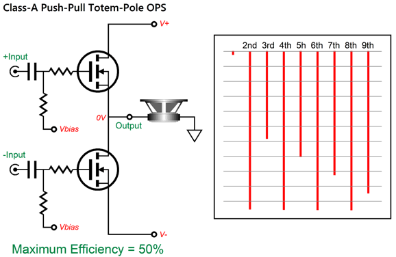
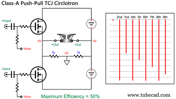
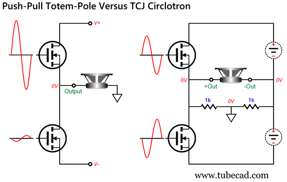
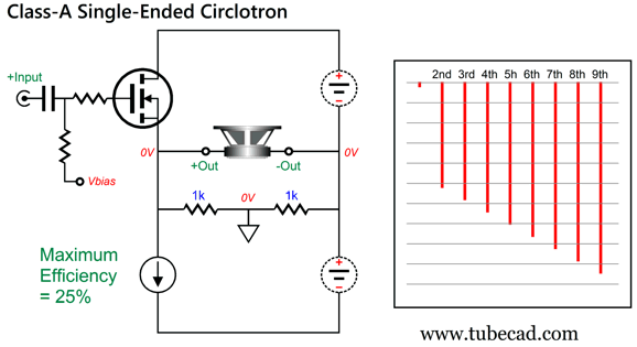
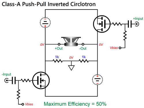
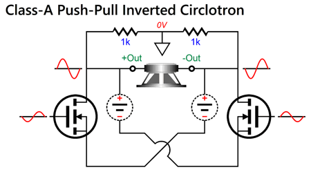
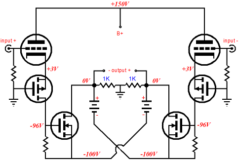

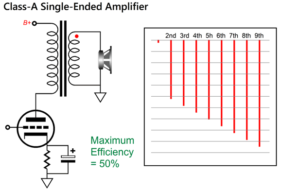
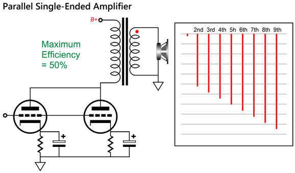
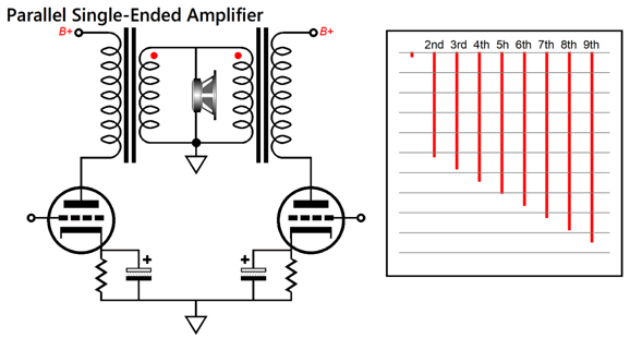
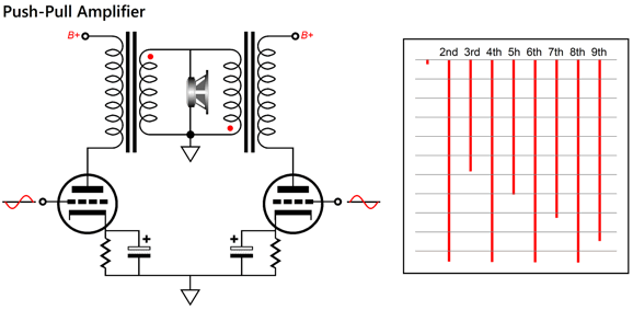
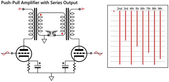


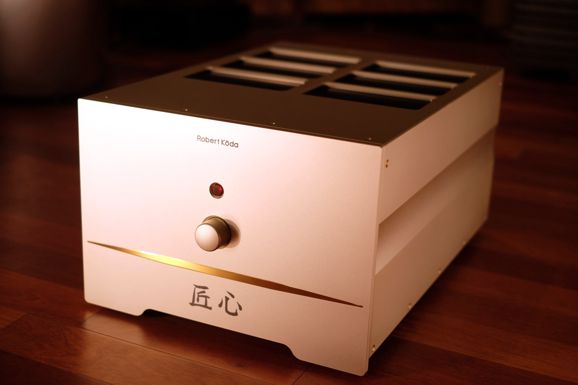
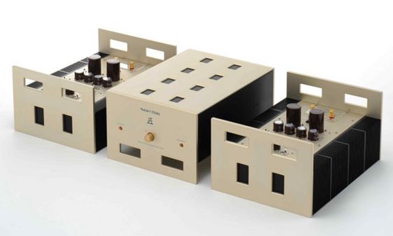 Image from
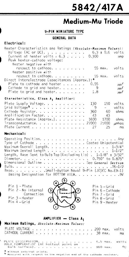


| www.tubecad.com Copyright © 1999-2023 GlassWare All Rights Reserved |