| John Broskie's Guide to Tube Circuit Analysis & Design |
29 March 2023 Post Number 579
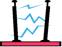
Single-Ended Electrostatic Amplifiers Long ago, single-ended electrostatic speakers were made, which held a diaphragm and one stator. Alas, they didn't work well, producing more distortion than was tolerable. In addition, if they were not designed correctly, they would cause frequency doubling, wherein 1kHz would go as electrical signal, but 2kHz would come out as sound. The electrostatic loudspeaker that we use today uses two stators, and it must be driven by a balanced signal, a very high-voltage balanced signal, as in up to a few thousand volts.
This explains instantly why direct-drive electrostatic power amplifiers are so very rare. Beyond the issue of finding output devices capable of surviving truly high voltages (as in a few thousand volts), staggeringly high-voltage power supplies are pain to build, due to the cost and scarcity of high-voltage rectifiers, power transformers, and capacitors of sufficiently high voltage and high capacity. Thus, almost all electrostatic loudspeakers contain a step-up audio transformer that accepts the output of say +/-40Vpk from a power amplifier—be it solid-state or tube-based, single-ended or push-pull—and increases the voltage output to something like +/-2kV.
Since electrostatic headphones do not require the same huge voltage swings that an electrostatic loudspeaker does, building a high-voltage direct-coupled amplifier is both possible and desirable. Why desirable? Making a high-quality audio transformer is not easy or cheap. In contrast, building a high-voltage amplifier is relatively straightforward and less expensive. In addition, an electrostatic headphone amplifier just begs to include some tubes in its circuitry, as the needed+/-400Vpk output voltage swings are well within a vacuum tube's sweet spot. Every direct-coupled electrostatic headphone amplifier I have seen, however, which includes the five or six that I have built, are push-pull designs.
Typically, we see one 6CG7 or 6SN7 or ECC99 twin-triode tube per channel, configured as a long-tail differential amplifier.
A few audiophiles have told me that they do not like electrostatic headphones. I then ask which all-tube electrostatic headphone amplifier they used. None, is the universal answer, as the electrostatic headphones heard either attached to a step-up transformer or to pure solid-state or to hybrid tube-solid-state headphone amplifiers. Whereupon, I make the observation that he really haven't heard electrostatic headphones at their best. Well, the same can be said to me, as I have never heard my Stax electrostatic headphones driven by a high-voltage single-ended electrostatic headphone amplifier. I, however, so want to hear what a single-ended amplifier can impart to the experience, as electrostatic headphones deliver a higher resolution than any dynamic headphones that I have heard, no matter how expensive. Whoa, slow down, John, if there are two stators, then you must use a push-pull output stage to drive them directly, period. No exceptions. Everyone knows this. The underlining confusion here lies in conflating balanced and push-pull into a single concept. Balanced and push-pull are, nonetheless, different schemes, structures. They are not synonymous. A balanced signal requires two wires, with each presenting the same impedance relative to ground (the receiving circuit's signal reference). How that signal was created is not essential, but what is essential is that the circuit receiving the balanced signal sees an identical impedance from either wire relative to its signal reference (i.e. ground). Push-pull operation requires at least two output devices and, equally important, two phases of signal current conduction. Single-ended output stages can hold two or four output devices, but they only contain one signal-current phase of conduction, as all the output devices work in parallel. Weirdly, I am reminded of what Goethe said of love and marriage,
Imagine if someone told you that all motor vehicles had to have at least four wheels. You point out that motorcycles have only two wheels and are nonetheless motor vehicles, as are three-wheel motorcycles and cars. Undaunted, your exasperated friend explains that he has defined motor vehicles to mean at least four wheels and a motor. Great, let him write his own dictionary, but do not let him enter a biker bar. Here is an example of a single-ended signal source delivering a balanced output signal: we take a simple transistor-based, battery-powered radio and house it in a wooden box, which is otherwise sealed, save for a small hole that allows two twisted wires to exit. Every stage in the radio is single-ended in topology, yet the two wires present a balanced output signal. Balanced signals do not depend on or necessarily require push-pull output stages. Of course, the radio could have held a push-pull output stage, but the output signal would remain balanced. If the radio, however, were not powered by batteries, instead plugging into the wall socket, things would get complicated, as the thorny issue of house ground arises. In other words, the two wires might or might not present a balanced signal, depending on how the radio was grounded relative to the house ground. We would have to measure the impedance of each wire relative to ground to find out.
Okay, let's return to the topic of driving an electrostatic loudspeaker or headphone directly with a single-ended output stage. The question you should be asking yourself is, Since everyone uses a push-pull output stage, why should we bother with a single-ended output stage? Here is the answer:
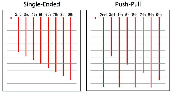
Our ears find the single-ended smooth cascade of harmonics more pleasing than the typical push-pull jagged tumble of harmonics—even though the graph on the right represents a lower THD (total harmonic distortion); sometimes less is not more; indeed, sometimes it is less. (Perhaps you have tasted perfectly purified distilled water, did it taste good? Not to me, as I found it tasting too much like dihydrogen oxide or oxidane.)
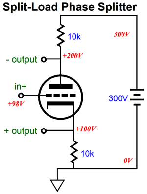
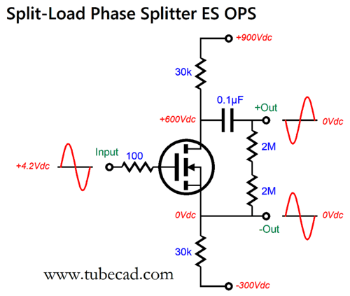
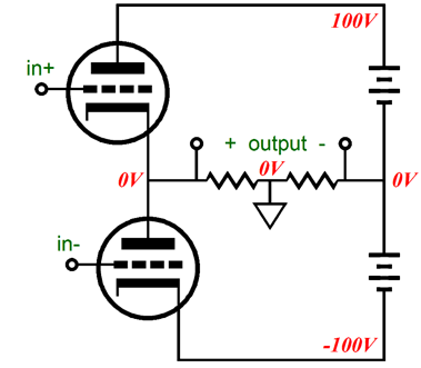
Split-Load Phase Splitter Electrostatic Output Stage
We see a single triode and, more importantly, a single current path from ground to the B+ voltage. As the triode's current conduction varies, so will the two output voltage swings, but in anti-phase. Relative to ground, the top output's output impedance is far, far higher than the bottom output's. Relative to each other, i.e. one output to the other, there is only one output impedance and it's far lower than most imagine. If the differential output voltage swing is high enough, we can drive an electrostatic headphone element, which essentially is just a capacitor. Here is a high-voltage split-load phase splitter suitable for this task.
The 12B4 is a single-triode tube that is quite robust; in fact, it was used as the output tube in a Futterman OTL power amplifier. Here is what the tube manual tells us about the 12B4.
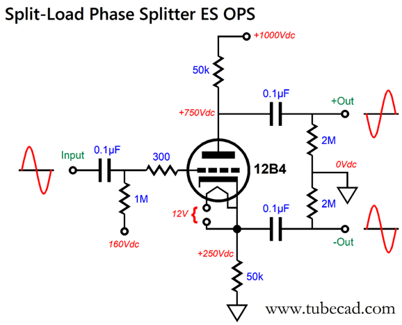
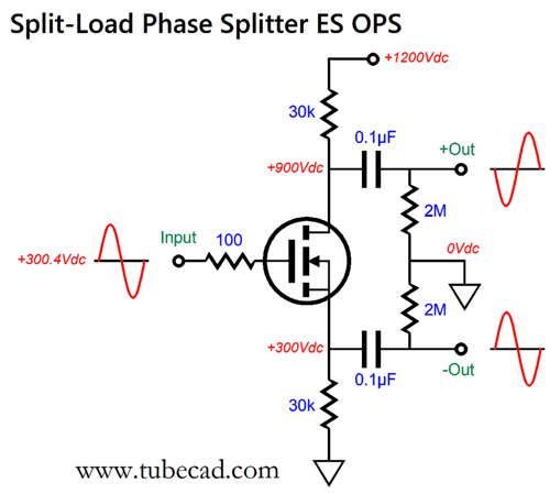
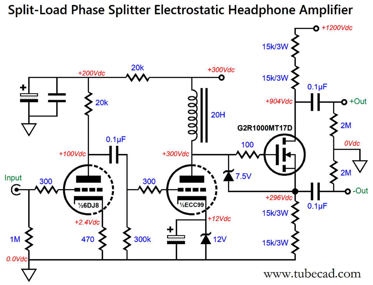
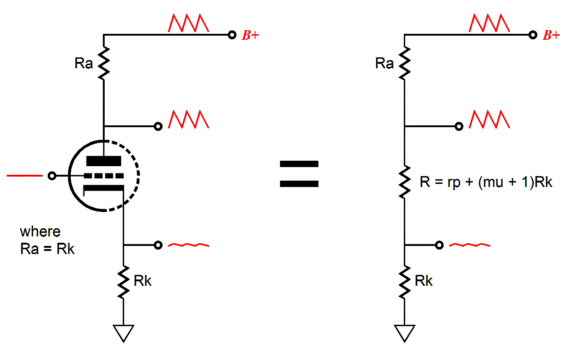
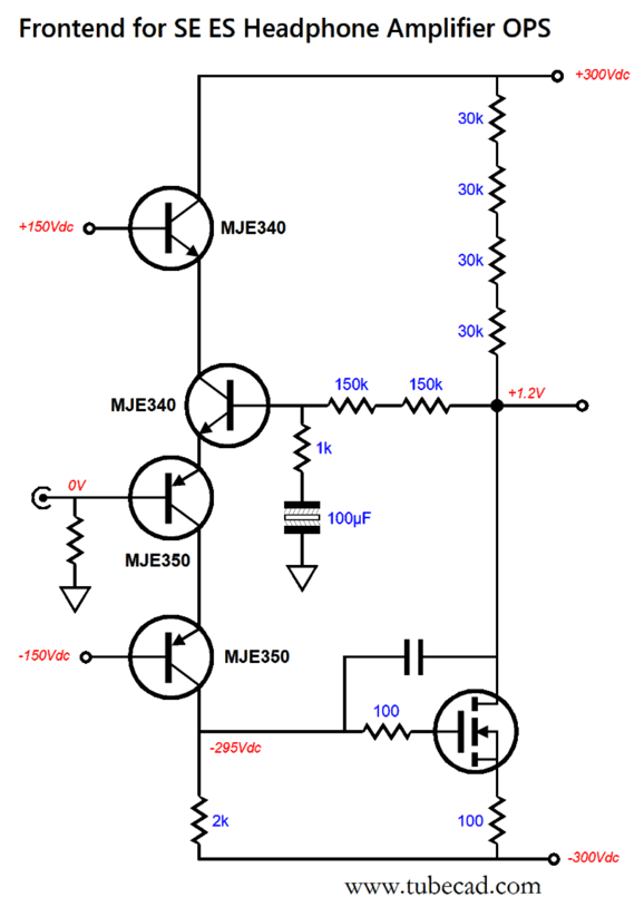
NOS 12B4 tubes are cheap, but still quite impressive, as the little noval triode can withstand an idle plate voltage up to 550V, with peak plate voltages up to 1000V, and with a maximum plate dissipation of 5.5 Watts and a peak cathode current flow of 105mA. In addition, the triode's input capacitance is a wee 5pF. Tubes are amazing. Thomas Mayer has devoted a webpage to the triode. Returning to the schematic, we see a whopping 1000Vdc B+ voltage and plate and cathode resistors that equal 50k of resistance. Each resistor will dissipate 1.25W and experience 5mA of idle current flow. The 12B4, undergoes the same 5mA of current conduction, but sees a voltage drop of 500V at idle, making for 2.5W of dissipation. Effectively, the split-load phase splitter develops a gain close to two—that is if we sum the two outputs differentially. The two output coupling capacitors are terminated by 2M resistors to ground. The key safety feature in the schematic is the floating heater power supply that must be referenced to the 12B4 triode's cathode, not ground. In other words, the heater power supply must swing up and down with the cathode, which means that each channel must get its own floating 12V heater power supply. (Since the 12B4's heater element is center-tapped, we can forgo using a 12Vdc power supply and use a 6.3Vac secondary by attaching pin 3 to pin 1, the cathode pin.) With only a gain of two, what is needed to drive the split-load phase splitter to 450Vpk differential output is a high-gain, high-voltage frontend. Since the 12B4's transconductance is relatively weak, especially compared to any solid-state device, we must add the -90V bias voltage to the needed input voltage swing, resulting in a 540Vpk differential input signal; in other words, +/-270Kpk. Yes, this is a hairy project, but then so are all electrostatic headphone amplifier projects. One workaround is to forgo the plate and cathode resistors, relying on a center-tap inductor instead.
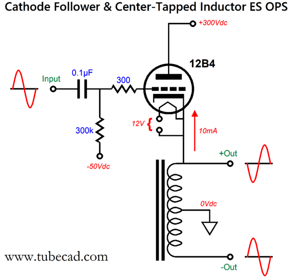
The 12B4 only sees a B+ voltage of 300Vdc, but it idles at twice the current, 10mA, which will improve the sound by moving the triode's operation out of the gooey bottom of the plate curves. (The plate dissipation rises to 3W, but it's worth it.) The required drive signal amplitude can be increased to +/-300Vpk, which would yield a larger differential output voltage swing of 500Vpk. The huge problem is finding an audio-grade center-tap inductor with sufficient inductance. Not an easy task. Alternatively, we could try one of the new SiC MOSFETs (SiC stands for silicon carbide), which offer far lower input capacitance and reduced power loss. They used to be quite expensive, but their price keeps dropping. An interesting SiC MOSFET is the G2R1000MT17D, which is a 44W, 1.7kV SiC MOSFET in the TO-247 package. Its input capacitance is a mere 111pF, a small fraction of the typical silicon MOSFET.
We can replace the 12B4 (and its floating heater power supply) with this $6 solid-state device.
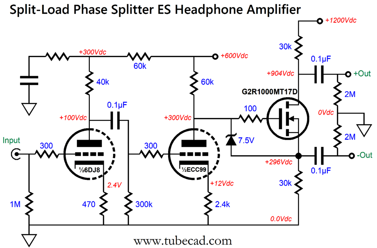
The B+ voltage has been raised to 1200Vdc and the SiC MOSFET draws 10mA, making for a dissipation of 6W, with a potential differential peak output voltage swing of nearly 600V, or +/-300Vpk per output. It still requires a huge input signal, but not as much as the 12B4 triode. Here is one possible frontend for the G2R1000MT17D.
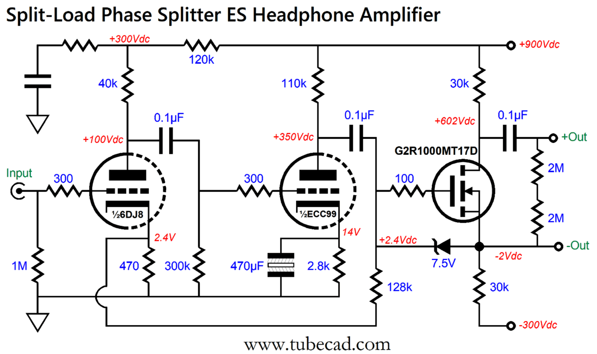
The 6DJ8 and ECC99 will require a little over 1Vpk of input signal to drive the single-ended output stage to full output. We could run a lower B+ voltage for the tube-based frontend by using inductor loading of the ECC99 triode's plate.
Note the 300Vdc power-supply rail. Also, note the bypass capacitor on the ECC99's cathode resistor, which will lower the ECC99's output impedance. Once again, however we run into the problem of sourcing a high-quality, audio-grade inductor (choke), as power-supply chokes won't cut it. What about including a negative feedback loop, so the input triode controls the MOSFET's output? It could work, but keeping the three stages stable might prove difficult. Moreover, the PSRR might worsen, as the negative feedback would result in a great PSRR figure at the cathode, but a much worse PSRR at the plate. On the other hand, we could employ the negative feedback loop only over the tube portion of the circuit. I would, however, make one big change first; namely, I would add a -300V power-supply rail and lower the B+ voltage by 300V.
As far as the G2R1000MT17D is concerned, nothing important has changed, as it still sees the same voltage drop and idle current flow and the same drain and source resistors. Now, we can add the frontend that extends its negative feedback loop only over the tubes.
The cynosure Aikido mojo resistor is there tweak the amount of ripple leaking into the ECC99's grid for the optimal PSRR, as the split-load phase splitter offers poor PSRR at its plate output.
The workaround is to strive to achieve equal amounts of power-supply noise (in phase) at each output, so the intrinsically differential electrostatic driver is blind to the noise. In the push-pull long-tail differential amplifier output stage, the amount of power-supply noise is equal at each output, resulting in a naturally great PSRR. With a split-load phase-splitter output stage, we must earn a great PSRR, as it's not given to us for free.
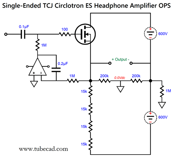
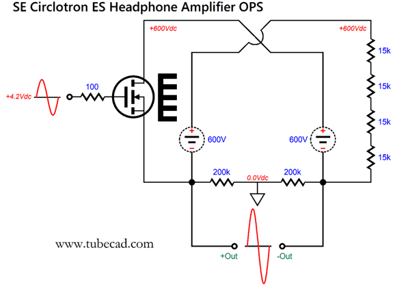
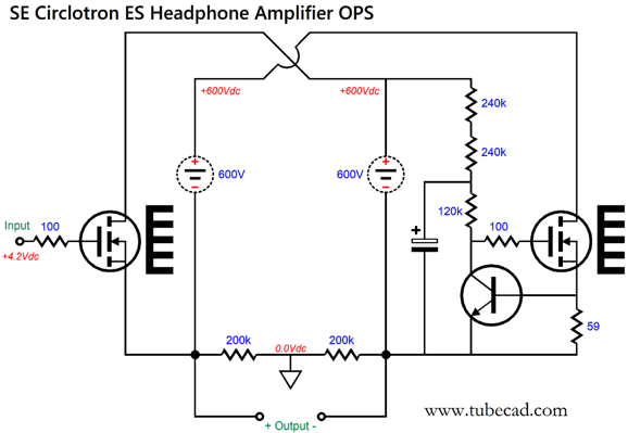
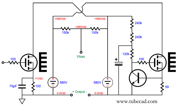
Single-Ended TCJ Circlotron OPS
Ground falls mid load and the output stage delivers a gain of roughly 1:2 (+6dB). To convert this output stage to a single-ended one, requires losing the bottom output device, replacing it with a load resistance.
The four 15k resistors combine to create 60k load for the MOSFET. Since the 60k load sees a 600V voltage drop, the current flow through the MOSFET and bipolar power supply must be 10mA. Just like the split-load phase splitter version, this single-ended output stage requires a huge input signal to be driven to full output, which can approach 600V peak-to-peak. In other words, the MOSFET's gate can see an input signal up to about +/-290Vpk. The OpAmp works as a DC servo to prevent a DC offset developing across the two outputs. We can get extra fancy by replacing the load resistors with a constant-current source.
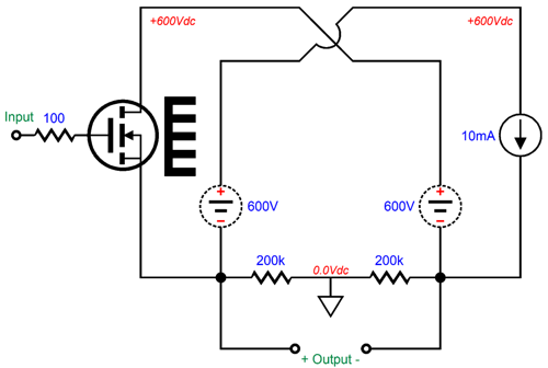
The constant-current source lowers the distortion and extends the high-frequency bandwidth. Making a high-voltage constant-current source is not that hard, as we can just use another high-voltage MOSFET.
Note how the constant-current source is auto-biased by the NPN transistor and how the loop of current flow through the transistor and its collector resistors is contained to the bottom floating power supply. In other words, this current flow does not unbalance the output stage or lead to a DC offset. How do we drive this single-ended output stage? We could use tube-based frontend from the section or we could build a high-voltage solid-state frontend. A cascoded bastode input stage driving a common-source amplifier might prove fun.
The MOSFET could be replaced by a high-voltage NPN transistor, such as the FJPF5027OTU, which is a 800V transistor in the TO-220 package. The 1.2V DC offset does not matter, as the single-ended circlotron output stage is capacitor coupled. The negative feedback loop resistors impose a gain of 1:301, which is plenty.
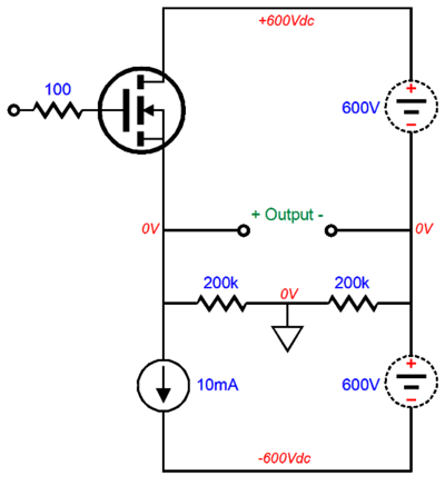
Single-Ended Conventional Circlotron
Note how all the parts are the same as in the previous TCJ circlotron, but differently arranged, save for the two 200k resistors that from a two-resistor voltage divider in both circuits that center-taps the balanced output and references it to ground mid-load. The same gain of roughly 1:2 obtains, as does the same output impedance. The 60k worth of load resistance sees the same voltage drop as the MOSFET, which thereby sets the idle current flow through the MOSFET to 10mA, thereby creating 6W of heat dissipation by the MOSFET. We can replace the load resistors with a high-voltage constant-current source.
Once again, the easy way to build a high-voltage constant-current source is to use another high-voltage MOSFET.
Everything functions as it did in the previous TCJ circlotron. A circlotron is a circlotron is a circlotron. Okay, let's now do something interesting.
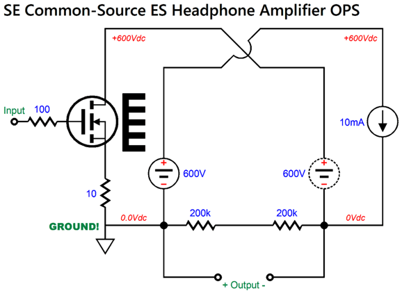
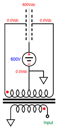
Common-Source ES Amplifier
This small change makes a huge difference, as the MOSFET no longer functions as a source follower of sorts, but as an amplifier that delivers a big gain—possibly far too much gain, due to the constant-current source loading. Therefore, let's go back to using load resistors and increase the source resistor value.
A small input signal goes in and a huge output signal emerges. Based on the resistor values, we can expect a gain close to 1:600. The 75pF capacitor improves the high-frequency bandwidth. The two 200k resistors no longer ground the output mid load, but do give the amplifier something to bite on other than the load capacitance presented by the ES headphone. The big HOWEVER is that the output is no longer balanced. Yes, we get a huge gain, but only at the inverting output. How can we drive an electrostatic headphone driver with this very single-ended, single output? The answer is that we must think like Copernicus or Einstein. (It doesn't hurt to be sneaky in general. "Sneaky is my euphemism for "clever," which troubles some, coming off as arrogant or supercilious. Indeed, using the word "supercilious" is also deemed supercilious.) Let's examine a conventional electrostatic setup.
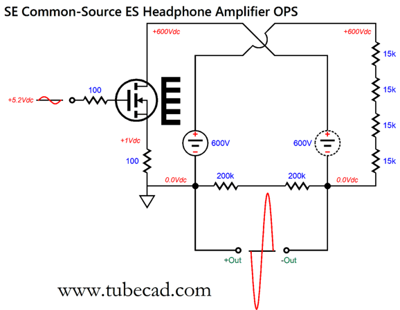
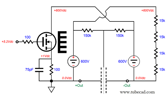
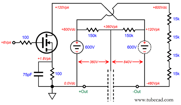
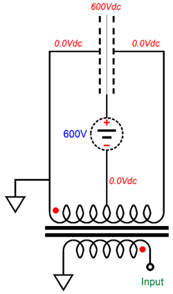
The step-up audio transformer provides the needed voltage gain, while the 600V power supply delivers the needed bias voltage for the diaphragm. We can deliver the same 600V bias voltage by losing the two 200k resistors and using two 150k resistors at the top of the power supplies, both the floating power supply and the grounded power supply.
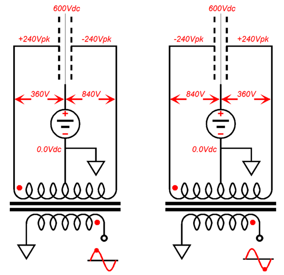
Note that the 600V power supply on the left is ground referenced, while the one on the right is floating; thus, my change in the symbols used. It may be hard to believe, but we have produced a workable alternative to the conventional electrostatic setup. Let's apply a 0.8V positive input voltage and observe the resulting voltage relationships.
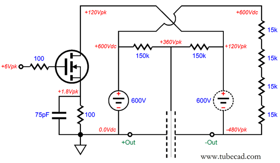
The inverting output swings 480V negatively, while the bias voltage falls to 360V. Now, we apply a -0.8V input signal and see the results.
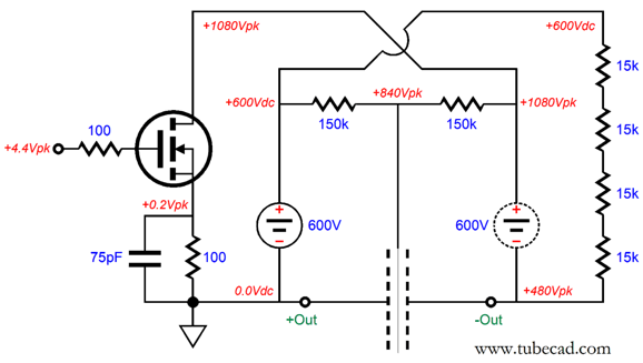
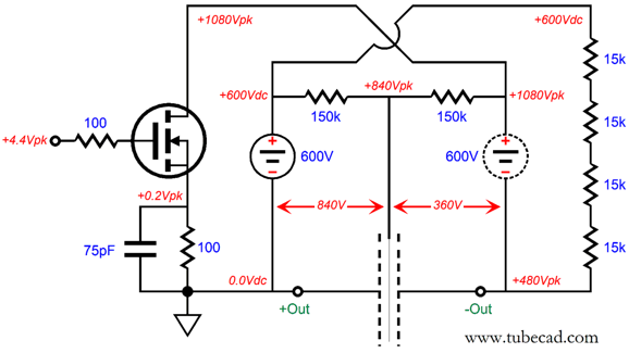
The inverting output swings 480V positively, while the bias voltage rises to 840V. Well, what good has this done us? Plenty. Let's compare these results with those from a conventional electrostatic setup.
The two stators see the same 480V differential voltage that existed in the single-ended circuit, while the bias voltage remained constant at 600Vdc. The big question is, What voltage relationships exist in single-ended version between the diaphragm and its stators?
The diaphragm experiences a 360V differential between it and the stator at its left; an 840V differential with the stator on its right. Compare these voltage relationships to the conventional electrostatic. Amazing isn't it? The exact same 360V and 840V voltages and the same 480V differential between stators. How about when the single-ended version swings positively?
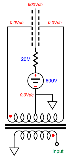
The exact same 840V and 360V voltages and the same 480V differential between stators. As far as the diaphragm and its stators are concerned, nothing has changed between the single-ended version and the push-pull transformer-coupled version. The diaphragm experiences the exact same attraction and repulsion as in the transformer-coupled version; therefore, the diaphragm undergoes the exact same excursions, producing the same SPL at our ears. The diaphragm does not care where we ground the circuit, as long as the same voltage relations obtain. Now, the knowledgeable electrostatic fan points out that we do not have an apple-to-apple comparison going on here, as most electrostatic loudspeakers use a constant-charge arrangement wherein the diaphragm gets its bias voltage through a high-ohmage resistor, a staggeringly high ohmage resistor.
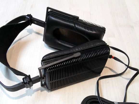
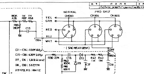
In contrast, my novel arrangement uses relatively low-valued resistors to establish the moving bias voltage. True, ever so true. But electrostatic headphones, such as those made by Stax do not use a high-ohmage bias resistor, which is revealed by examining the schematics from Stax, for example, the Stax SRM T1.
Here we see two bias voltages created, one for the lower-voltage standard (normal) headphones and a higher voltage for the pro models. In both cases, the bias voltage just attaches to the electrostatic headphone jacks, which no intervening high-ohmage resistor. (Perhaps Stax incorporates a high-ohmage resistor in each headphone cup, but I have never taken one apart to find out.) Examine the Stax connecting cable and see the six wires within. In other words, to make my novel ES headphone amplifier work with the Stax ES headphones will require using a new 6-prong plug and 6-pin jack, which really isn't that big of a deal. But isn't the intervening high-ohmage resistor essential? Apparently not in the Stax headphones. Think about the situation: electrostatic loudspeaker present a capacitance vastly greater than electrostatic headphones; therefore, the typical 20M series resistor would have to be equally vastly greater in resistance to achieve the same constant-charge effect. As far as I know, no one makes a gig-ohm resistor. Moreover, I have heard electrostatic loudspeakers that drive the diaphragm, not the stators. In these inverted electrostatic speakers, the diaphragm is low-ohmage and the no high-resistance series resistor is used. Okay, we have established that this novel single-ended electrostatic amplifier yields the results as a more conventional push-pull design, but what does it buys us other than novelty for the sake of novelty?
Think about what a hard sell the first electrostatic headphones must have been. The buyer must be willing to place next to his ears high-voltage sound-producing devices. Ears get hot when covered with headphones and they sweat. Do you really want any part of your body near high voltages? The workaround was to place a good bit of voltage-insulating material between your ears and the closest stator. With my novel arrangement, we would place the grounded stator next to the ear, without the need for voltage-insulating, sound-muffling material. Even with electrostatic loudspeakers, great care is taken to hide the stators behind non-removable grills or to coat the stators with thick insulating paint or a fused powdered plastic coating. With the novel arrangement, the exposed stator could be made of anodized perforated aluminum or stainless steel. Of course, we could just ground the ear-facing stator.
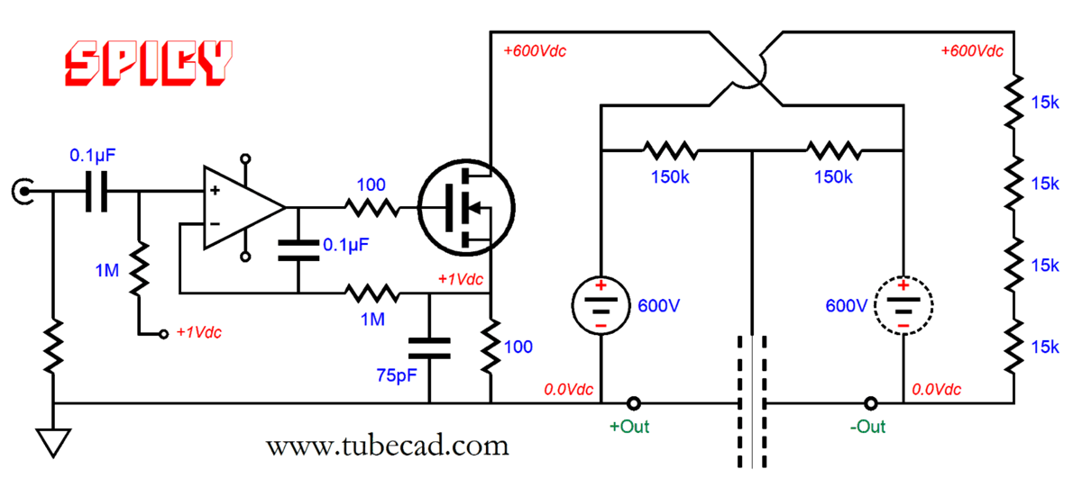
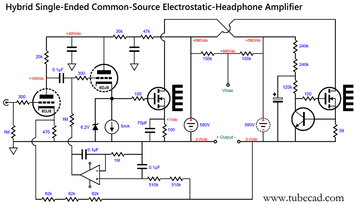
The bias-voltage power supply is now floating, but as far as the diaphragm is concerned, nothing has changed. The HV bias-voltage power supply must be truly floating. This means we must be wary of the capacitive coupling between its transformer's primary and secondary and of any connections to house ground. In addition, this common-source amplifier arranged horizontally setup allows us to forgo the otherwise required high-gain frontend, as the high-voltage SiC MOSFET delivers enough gain to be driven by only 1Vpk of input signal, not the 90Vpk that a 12B4 would need. In other words, we can create not only a single-ended electrostatic headphone amplifier, but also a negative feedback-free single-ended electrostatic headphone amplifier. Mercy. How I would love to hear it. Here is an input OpAmp could be used as a unity-gain buffer and auto-bias circuit.
This is an example of a truly SPICEy circuit: one that works fabulously well in SPICE simulations, but falls on its face in reality. Why? In SPICE, the voltage sources are unvarying, as are the resistor values. In reality, the power-supply voltage, unless tightly regulated, varies with the wall-voltage shifts; high-wattage resistors usually come in 5% tolerances. For example, a mere 5% shift in wall voltage will yield a B+ voltage between 570Vdc to 630Vdc. The workaround is to use an OpAmp-based DC servo (and unity-gain buffer) to monitor the DC offset at the inverting output.
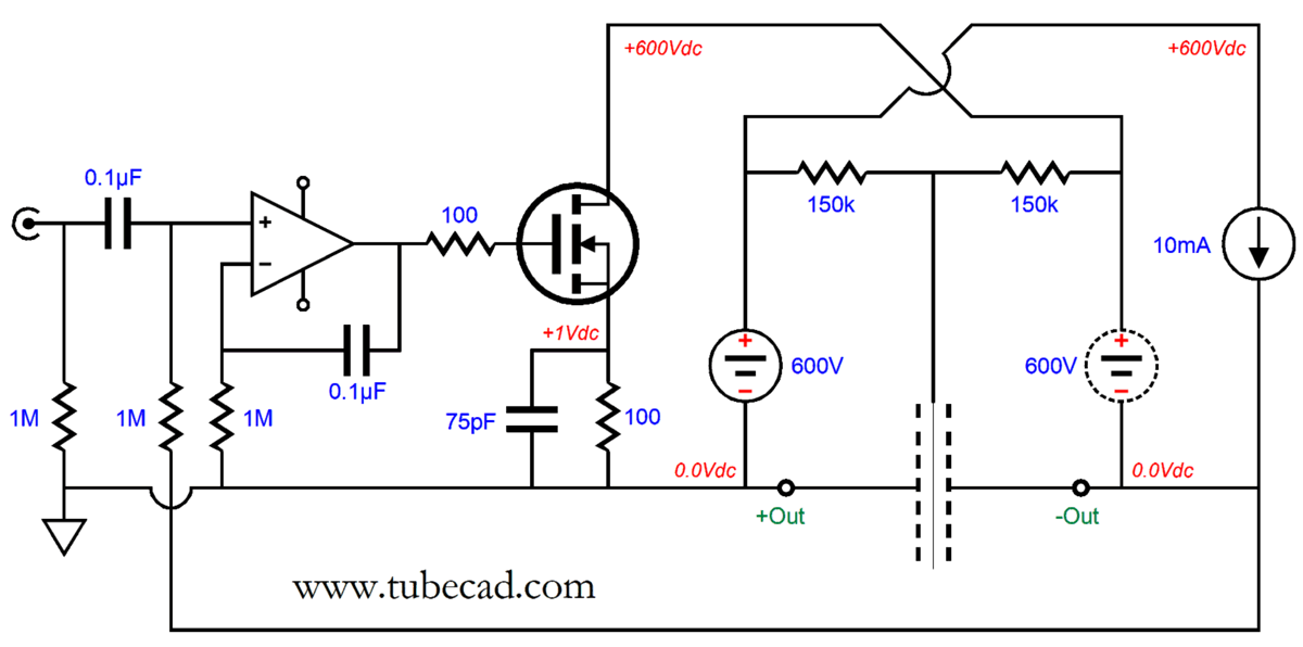
In terms of AC signals, the OpAmp is a no-gain buffer; in terms of DC voltages, a DC servo. While I am at it, I should show how the constant-current source is put together.
Both MOSFETs will each dissipate 6W at idle, so the heatsinks are required.
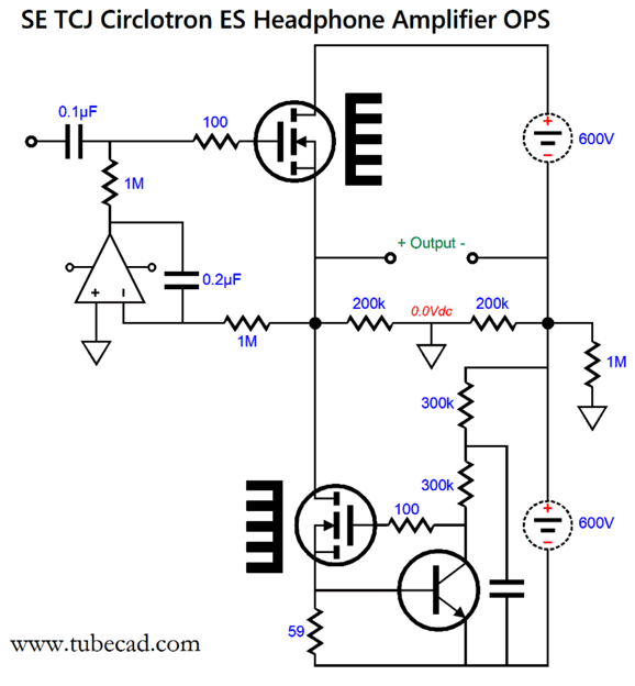
Of course, many, myself included, might prefer the addition of some tube magic.
This electrostatic headphone amplifier uses a 6DJ8-based frontend to drive the MOSFET on the left and an OpAmp to prevent a DC offset. The input 6DJ8 triode provides the gain and the other triode functions as a cathode follower to drive the MOSFET with a low impedance. The OpAmp should be one with a FET input stage. The input triode inverts, as does the MOSFET common-source amplifier, so the net result is non-inverting amplification.
Note the two series of resistors, one for the 6DJ8's negative feedback loop and one for the DC servo. Why? High voltages. If you look at a resistor's data sheet, you find its maximum voltage differential, which is not based on its power dissipation, but on its tendency to internally arc. We often see voltages between 200V to 400V. In addition, resistors can exhibit a voltage-induced distortion, which placing many resistors in series sidesteps. In fact, as you look over the schematics in this post, think of several resistors in series. Let's use one of the early schematics to make an example.
The two 60k resistors should be made up of three 20k/1W resistors; the two 30k resistors, three 10k/2W resistors; the 40k plate resistor, two 20k/1W; and the two 2M resistors, two 1M resistors.
UPDATE
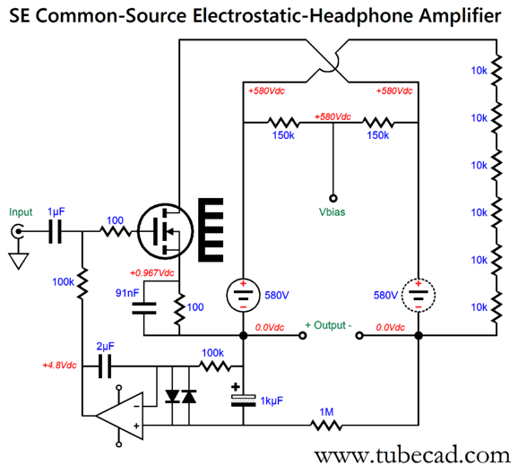
Instant Update
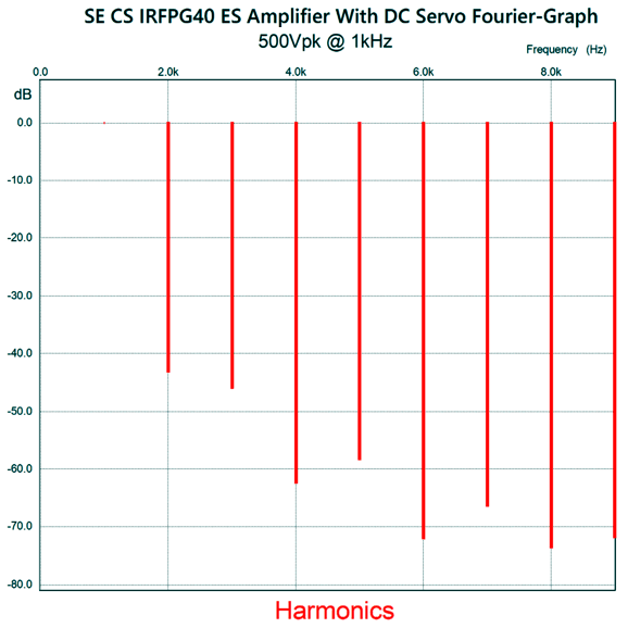
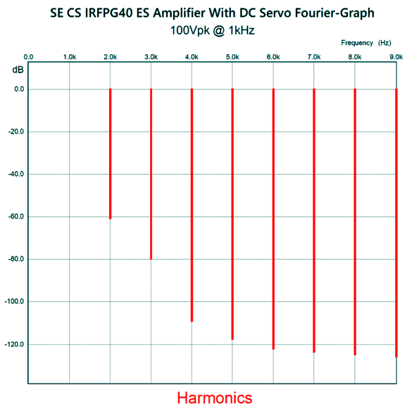
Note the 580Vdc power-supplies; Stax uses 580V for the bias voltage on their Pro models. Also note the rather large 91nF (0.091µF) bypass capacitor across the 100-ohm source resistor. I found that I had to tweak the DC servo capacitor values to get a flat bass response. (I added the two 1N4148 diodes to protect the OpAmp at startup and prevent latch up of its output.) I discovered that a CCS load created so much gain that the amplifier was unuseable with a negative-feedback loop, so I opted for drain resistors instead. With an input signal of 1Vpk and an output voltage swing of 500Vpk (1kVpk-to-pk), the THD was below 1%.
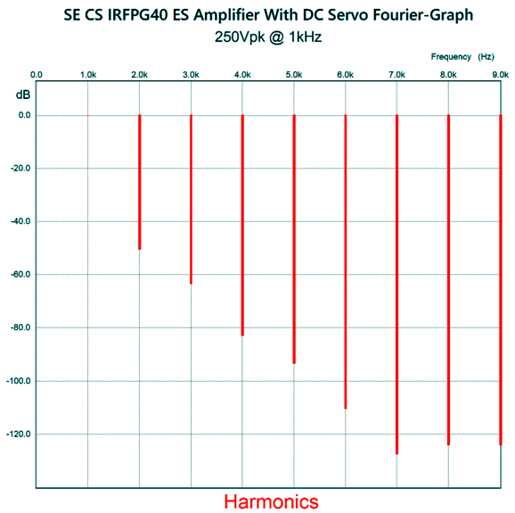
At half voltage (250Vpk), the lovely single-ended cascade is more pronounced.
When the output voltage swing is reduced to 100Vpk, the THD falls to 0.1%, which makes me wonder what a SiC MOSFET could produce, as its low capacitance would reduce phase shift at 1kHz.
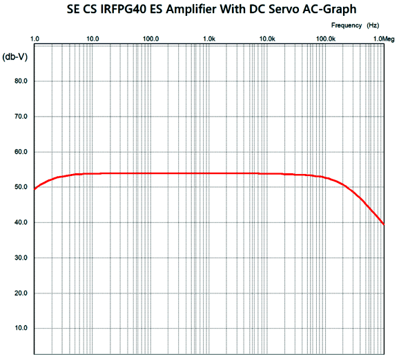
The frequency response plot is quite impressive.
Without the source-resistor bypass capacitor, the high-frequency -3dB frequency was 16kHz; with the capacitor, 190kHz. At the other end, the low-frequency -3dB frequency was 1.4Hz.
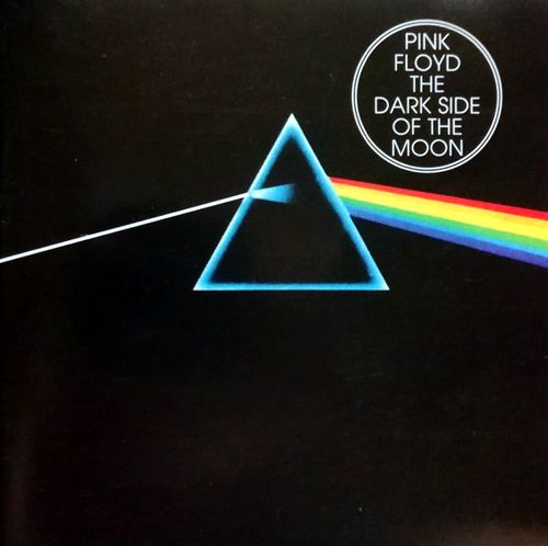
Music Recommendation: The Dark Side of the Moon Well, this made me wonder what other old hit albums have been released in high-res. The search was on and I discovered that both Amazon Music and Qobuz offer Pink Floyd's 1973 album, The Dark Side of the Moon, in 24-bit, 192kHz resolution. The album's genre is hard to specify, as it has been categorized as Art Rock, Experimental Rock, Hard Rock, Progressive Rock, Psychedelic Rock, Space Rock... It was the perfect album for teenagers filled with existential crisis, i.e. the conviction that life lacks meaning, along with a big heap of despair, dread, and depression. Ah, the 1970s. For me, it was the album that compelled me to build better-sounding loudspeakers—but I have always been a cheerful pessimist. Listening to the album today, I found the high-res version sounding quite analog, far, far better than the CD version.
//JRB
Did you enjoy my post? Do you want to see me make it to post 1,000? If so, think about supporting me at Patreon.
User Guides for GlassWare Software
For those of you who still have old computers running Windows XP (32-bit) or any other Windows 32-bit OS, I have setup the download availability of my old old standards: Tube CAD, SE Amp CAD, and Audio Gadgets. The downloads are at the GlassWare-Yahoo store and the price is only $9.95 for each program. http://glass-ware.stores.yahoo.net/adsoffromgla.html So many have asked that I had to do it. WARNING: THESE THREE PROGRAMS WILL NOT RUN UNDER VISTA 64-Bit or WINDOWS 7, 8, and 10 if the OS is not 32-bit or if it is a 64-bit OS. I do plan on remaking all of these programs into 64-bit versions, but it will be a huge ordeal, as programming requires vast chunks of noise-free time, something very rare with children running about. Ideally, I would love to come out with versions that run on iPads and Android-OS tablets.
|
I know that some readers wish to avoid Patreon, so here is a PayPal button instead. Thanks.
John Broskie
John Gives
Special Thanks to the Special 79 To all my patrons, all 79 of them, thank you all again. I want to especially thank
All of your support makes a big difference. I would love to arrive at the point where creating my posts was my top priority of the day, not something that I have to steal time from other obligations to do. The more support I get, the higher up these posts move up in deserving attention.
If you have been reading my posts, you know that my lifetime goal is reaching post number one thousand. I have 430 more to go. My second goal was to gather 1,000 patrons. Well, that no longer seems possible to me, so I will shoot for a mighty 100 instead. Thus, I have just 21 patrons to go. Help me get there. Thanks.
Only $12.95 TCJ My-Stock DB
Version 2 Improvements *User definable Download for www.glass-ware.com
|
|||


| www.tubecad.com Copyright © 1999-2023 GlassWare All Rights Reserved |