| John Broskie's Guide to Tube Circuit Analysis & Design |
15 April 2023 Post Number 580
Some Good News The stepped attenuators based on the Grayhill gold-contact rotary switches, such as Attn-1, Attn-2, Attn-Ladder, and Attn-12 are back in stock—until I run out of switches again.
Lost Message A week ago, I received a message from a Patreon patron, asking for more information on how to bi-amp with the new low-power stereo amplifier from Schiit Audio, the Gjallarhorn. I cannot find it at Patreon or my email, sadly. When I first saw it, I was about to answer it directly, but then I thought it would make a good topic for my next post. Here it is.
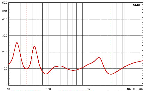
Active Crossovers for Two-Way Loudspeakers Put simply, passive speaker crossovers are a huge pain. How so? High-quality crossovers parts are expensive, such as air-core inductors and film & PIO capacitors; indeed, even high-quality power resistors cost a lot. Moreover, high-quality crossover parts, because they are so much larger than the cheap alternatives, subtract air volume from the speaker enclosure. In addition, the textbook crossover designs and formulas seldom work perfectly, as the speaker drivers rarely present flat impedances.
(Recently, I reviewed the data sheet for a purportedly 8-ohm woofer whose impedance plotline never intersected the horizontal 8-ohm line at any frequency.) Additionally, the speaker drivers impart unwanted intrinsic rolloffs and impedance peaks due to their own resonant frequencies and high-frequency limits. Lastly, care must be exercised in the physical arrangement of the inductors, as inductors placed side by side can inductively couple. Altogether—a first-rate nuisance. In contrast, active crossovers are small and cheap and do conform to the textbook formulas. Well, why then are they so rare? As long as power amplifiers were the most expensive component in an audio system, passive crossovers made a lot of sense. Today, high-wattage class-D amplifiers and class-AB amplifier chip amplifiers cost far less than one high-end crossover capacitor or inductor. Today, passive crossovers make less sense; soon, they will make far less sense.
My bet is that in a decade from now most loudspeakers sold will be both self-powered and wireless. Indeed, I expect to see new houses built without AC wall sockets, as inductive charging is taken to its logical and aesthetic end. Other than the makers of high-end audio cables, who doesn't hate wires? What could replaces wires?
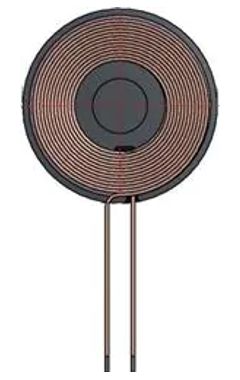
Inductive charging requires two coils of wire to be brought close enough to each other to couple inductively; then, an AC current flow through one coil will transfer to the other coil, creating an AC voltage that can be rectified into DC voltage. In the near future when building a new house, many charging coils will be arrayed across the bottom of the walls, each parked at the bottom where the wall meets the floor, hidden behind the drywall, sandwiched in between the vertical two-by-four framing. When an inductive-charging coil is needed, say to power a flat-screen TV, a special tool (a felt-covered ring magnet and electronic device) will be used to magnetically couple with the coil behind the wall; and, then, drag the coil up to the desired height, where it will remain due to the counterweight and pulley assembly or merely due to it clinging to a two-sided metal rail that will provide the needed AC voltage. Hell, who needs a special tool, as a long worm gear assembly could power the coil up and down to the desired placement, controlled by an app on your phone. A horizontal version would be arrayed across the floor. No visible wires anywhere; no visual blight. The hidden coils will only complete an AC circuit with the house AC voltage when needed—switched on by either actuating small magnet in the powered device or by a digital command sent through the AC voltage or by radio signal, such as Bluetooth or WiFi.
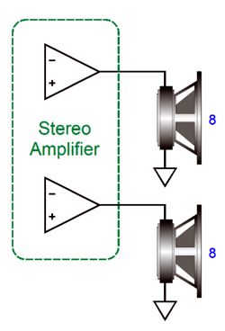
Returning to the wireful present, active crossovers and bi-amping allows us to overcome many loudspeaker problems that are otherwise impossible to fix with a passive crossover, such as using differing impedance woofers and tweeters or making asymmetrical, phase-flat crossovers. But let's start with the simplest crossover, the two-way first-order crossover.
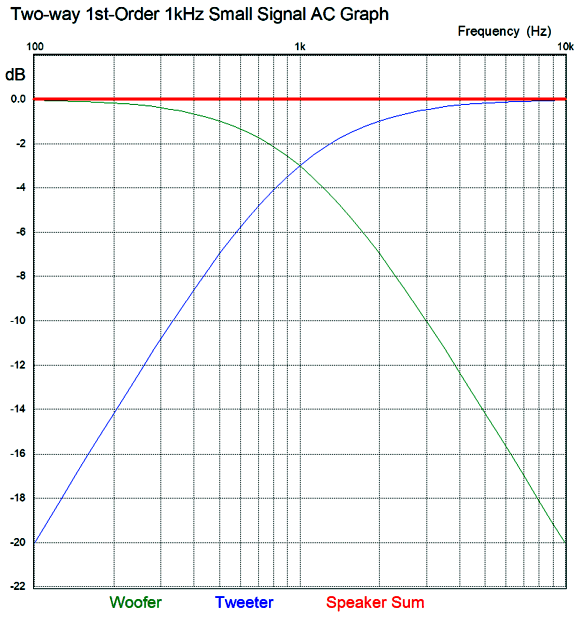
Active 1st-Order Two-Way Crossovers The 1st-order two-way crossover delivers a phase-flat output from acoustic sum of the speaker drivers. In other words, the loudspeaker can produce (or rather it can pass on) square waves, as the summed outputs produce zero phase shift. In contrast, 2nd-order and 3rd-order and 4th-order crossovers (which include the Bessel, Butterworth, Linkwitz-Riley alignments) do shift the phase, resulting in garbled square waves. Alas, the 1st-order crossover provides little protection to the tweeter, as its -6dB cutoff slope is so gradual that a lot of low-frequency energy appears at the tweeter's terminals.
The usual workaround is to add more drivers and use a three-way or four-way crossover. On the other hand, if two fullrange drivers were used in a two-way loudspeaker, the 1st-order crossover would prove ideal, as long as a low enough crossover frequency was chosen, say between 400Hz to 1kHz. Ideally, the distance between speaker cone centers should be far smaller than the size of the wavelength of sound at the crossover frequency. For example, with a crossover frequency of 500Hz, the wavelength is 27 inches (69cm). With two 6-in fullranges placed side by side, the 6-inch distance between centers translates into the wavelength of 2256Hz. Unlike any woofer-tweeter combination in existence, the two identical fullrange drivers will blend together seamlessly, as they share the same frequency and phase response.
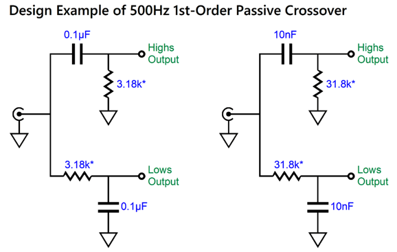
Assuming two fullrange drivers and a crossover frequency of 500Hz, a simple passive, i.e. no electronic devices, such as FETs or OpAmps or transistors or tubes, crossover can be made from just two capacitors and two resistors. Bear in mind, that simple does not necessarily mean easy.
Perversely, what seemed so simple has begat added complexity. Both versions are tuned to 500Hz, but the one on the left assumes a low output-impedance from the signal source, such as a robust line-stage amplifier or DAC. The one on the right assumes a high output-impedance from the signal source, such as a line-stage amplifier based on either a grounded-cathode amplifier or SRPP circuit or, even, just a volume potentiometer in a passive line stage. A 20k volume potentiometer presents an output impedance of 5k at -6dB position, which will entirely throw off the simple filters' crossover frequency. Even if a tube-based line-stage amplifier does offer a low output impedance, if its output coupling capacitor is only 1µF in capacitance, the filter circuit on the right is preferred. Why? The output coupling capacitor and the 0.1µF high-pass capacitor are series and create a combined capacitance of only 0.0909µF, which will shift the crossover frequency up to 550Hz. In contrast, the 1µF coupling capacitor in series with the 10nF filter capacitor results in a capacitance of 9.9nF. The resistor values get their asterisk of shame due their value only being accurate if the power amplifiers input impedance is infinite. It won't be, although a tube-based power amplifier with a 1M input resistor comes close. In other words, we must include the input impedance presented by the two power amplifiers in our calculations.
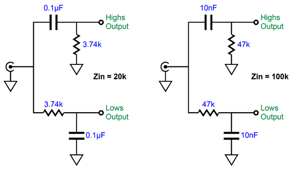
For example, the Schiit Gjallarhorn stereo power amplifier that I drooled over in post 578 presents an input impedance of 20k. If we include this 20k input impedance in our calculations, we arrive at this:
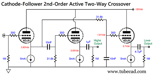
Once again, two versions of the circuit are provided. Taking one-step up from simple requires adding some electronics. For example, three cathode followers can be used to buffer the 10 filters from both the signal source and the power amplifiers.
The relatively high B+ voltage of 150Vdc (for a 6DJ8) is needed to ensure a high enough cathode voltage to use solid-state constant-current source loading. For example, the LM334 requires an overhead DC voltage of about 1V to work, to which we must add the expected AC voltage swing of about 1Vpk. (An Rset resistor value of about 13.7 ohms is needed for 5mA of current flow from the LM334.) The output for the high-frequency amplifier gets a 1µF coupling capacitor, whereas the low-frequency output gets a 4.7µF capacitor, which can be of a lessor quality and lower price. Of course, we could use these two output-coupling capacitors to set an additional high-pass filter, say at 100Hz, to limit the low-frequency load on the fullrange drivers. Assuming a 20k input impedance from the power amplifiers, an 82nF coupling capacitor is needed for both outputs. By the way, if the 31.6k filter resistors seem to be off the mark, as 31.8k is what the formula demands, it is due to two reasons: they do not make a 31.8k resistor and the cathode follower's output impedance (about 120 ohms) must be added to the resistor's resistance, making a total of 31.7k. The formula is simple enough. R = 159155/Freq/C where the capacitor value is in microfarads. A low-voltage version could be made with FETs, which would replace both the triodes and the constant-current sources; for most, however, OpAmps are the easier solution.
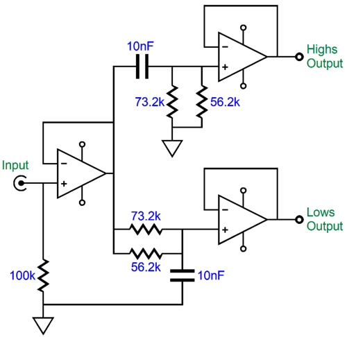
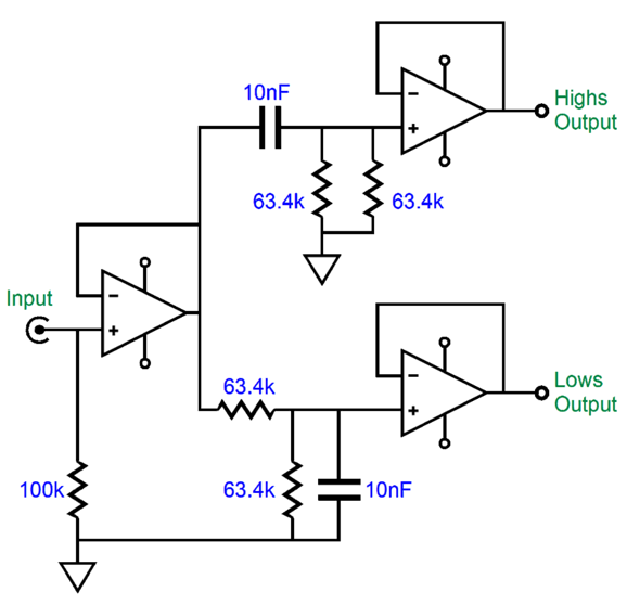
The three cathode followers have been replaced with three OpAmps. (In a stereo setup, three dual-OpAmps could be used.) Because the OpAmp's output impedance is so low, and because the OpAmp's input impedance is so high, we can use the formula's values for the capacitors and resistors. The problem of not being able to buy a 31.6k resistor was overcome by placing 56.2k and 73.2k resistors in parallel, thereby creating a 31.792k resistance. Dang close, in other words. Importantly, the OpAmps must be unity-gain stable. Some obvious choices are the AD712, LM4562, LT1028, LT1364, NJM2043, OPA134, OPA604, OPA1612, OPA1632, OPA1642, OPA1656, OPA2134, OPA2604, and OPA4134. I happen to like the smooth sound from the OPA2107, which sadly has grown expensive. Be sure to check the data sheet for the OpAmp to make sure that it is actually unity-gain stable, as I recalled this list from memory. Since we have gone active, we can add additional features. For example, small loudspeaker drivers and narrow speaker enclosures make for low-frequency diffraction loss, wherein the bass sounds thin due to the loudspeaker radiation having been only forward firing at high frequencies, but omnidirectional at low frequencies.
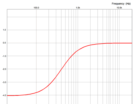
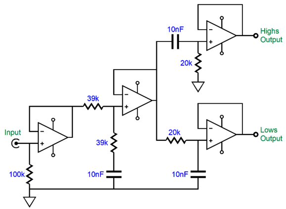
We can compensate for the low-frequency diffraction loss with a shelving network, which we can place ahead of the crossover filters.
An additional OpAmp was needed, but the circuit is not too difficult to understand. The two 39k resistors form a two-resistor voltage divider at high frequencies, but not at low frequencies, which creates a 6dB bass boost. No more thin bass. Of course, we can alter the low-frequency transition frequency or the amount of boost. I have found that the farther away from the wall the loudspeakers are and/or the more narrow the speaker enclosure is, the closer to the 6dB boost is needed. But with a fat speaker placed close to the wall or a corner, the smaller the amount of boosting is needed, if at all.
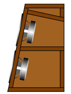
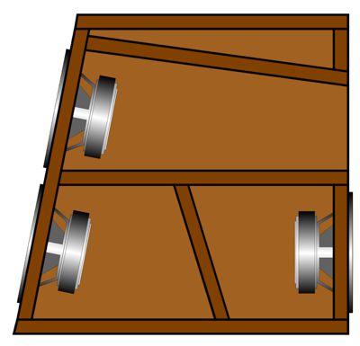
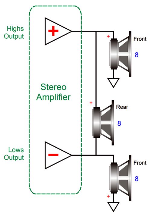
So far, everything that I have said could have been written by someone else. It's now time for one of my signature thinking-outside-the-box ideas, but inside the speaker-enclosure box this time. Imagine three identical fullrange drivers, two facing forward, one facing rearward.
The two front fullrange drivers crossover at 500Hz, while the single rear fullrange runs full out, i.e. fullrange. The top fullrange is loaded by a short transmission-line, which is stuffed with either wool or polyester fluff or fiberglass. The two bottom fullrange drivers are loaded by sealed, acoustic-suspension cavities. The front drivers are bi-amped, while the rear driver is configured in a bridge-amplifier arrangement of sorts.
The top amplifier is non-inverting, while the bottom amplifier inverts its input signal at its output. This explains why the bottommost driver has its positive terminal grounded. The mind-bending aspect of this arrangement is that although the top amplifier delivers the high frequencies and the bottom amplifier delivers the low frequencies, the rear-firing driver sees a flat frequency input signal at the same gain as the front drivers. In other words, at low frequencies, the top amplifier acts like a virtual ground for the bottom amplifier; at high frequencies, the amplifier roles reverse, so the bottom amplifier acts like a virtual ground for the top amplifier. At the crossover frequency, however, both amplifier's put out 70.7% of the signal amplitude that they would at their portion of the audio spectrum, along with +45 and -45 degrees of phase shift, which results in unity output for the rear driver. As far as both amplifiers are concerned, they are working into a 4-ohm load at all frequencies.
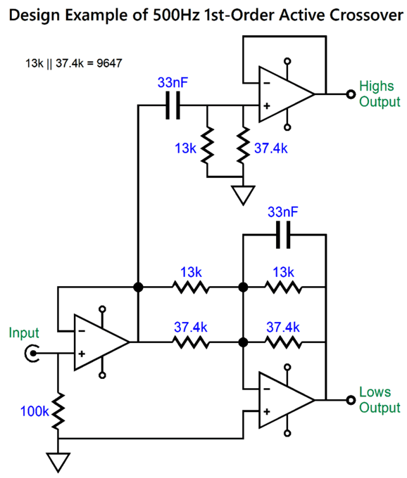
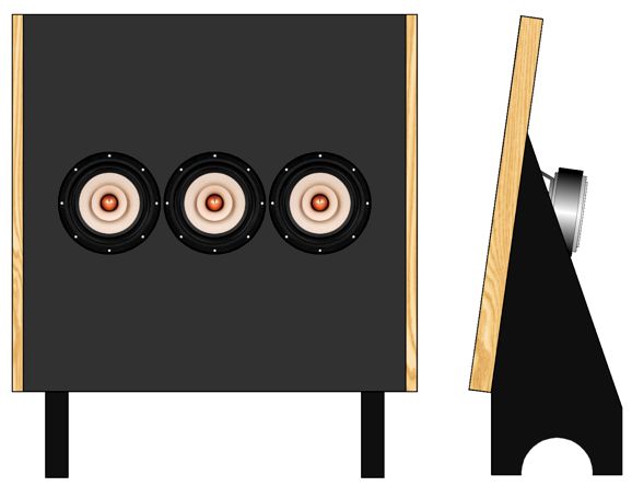
This is the required active crossover for this design. Note the inverting low-pas filter at the bottom. Thankfully, we no longer have to worry about low-frequency diffraction loss, as the loudspeaker radiates in a bipole fashion at high frequencies and omnidirectionally at low frequencies. For the best imaging and clarity, the loudspeakers should be at least two feet away from the rear wall. Okay, what if we take the three identical fullrange drivers and mount them on a dipole board, with the center driver handling the frequencies above 500Hz and the flanking two drivers handle the frequencies below 500Hz.
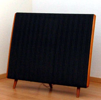
I have wanted to build this loudspeaker for decades now, as it was inspired by the famous Quad Model 57, which also held a center tweeter section and a low 500hz, 1st-order crossover. As everyone knows, it sounded fabulous.
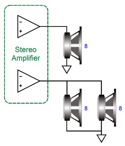
Making this loudspeaker design with passive crossovers, however, we run into problems: the two flanking drivers will halve the driver impedance and will deliver 6dB more SPL than the center driver, assuming the same fullrange driver is used throughout. With a bi-amplifier setup, in contrast, this is not a big deal, as we need only attenuate the signal sent to the low-frequency amplifier by -6dB, without incurring any wasted power or heat dissipation.
In fact, the bass amplifier will deliver more output power into the 4-ohm load (usually twice as much power).
Note how the two 63.4k resistors used in the low-pass filter also form a two-resistor voltage divider that halves the signal amplitude, giving us our desired -6dB attenuation. If you do not like the idea of solid-state OpAmps, the following circuit will prove a welcome relief.
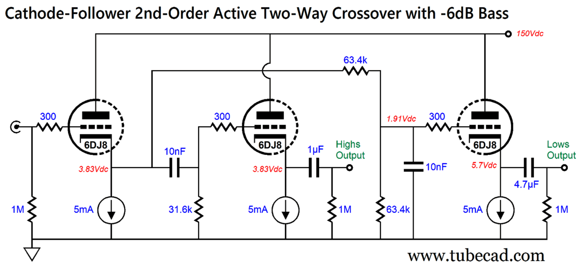
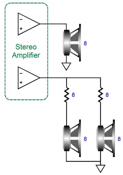
Once again, we see three 6DJ8 triodes used as cathode followers with the filter networks in between. And once again, the low-pas output for the bass power amplifier is attenuated by 6dB. Another potential workaround is to place 8-ohm power resistors in series with the woofers.
The bottom power amplifier now sees an 8-ohm load and no signal attenuation is needed. Won't this kill the amplifier's high damping factor? Yes, it will—thank God. Dipole loudspeakers run into the problem of overly damped drivers, drivers which were designed to work in either acoustic-suspension or bass-reflex enclosures; thus, their low Qts. For example, the Dayton fullrange driver, the PS180-8, presents a Qts of 0.23, which results in very thin bass in a dipole. (Dipole loudspeakers, both electrostatic and electrodynamic types, run a far higher Qts, as in well over 1.) The 8-ohm series resistors raise the Qts. By how much? Qts stands for a driver's total Q, which is a measure of its damping factor. Qts is found by placing its Qes (the electrical Q) in parallel with is Qms (the mechanical-system Q). Qes increases with the addition of a series resistance. Qes (new) = Qes*(R+RDC) / RDC Where R is the added series resistance. Using 8-ohm series resistors with the Dayton PS180-8 fullrange drivers increases their Qts to 0.48, which will result in about a 6dB improvement at its free-air resonance of 48Hz. In other words, instead of being down by over 12dB at 48Hz, it will be down only 6dB. (See post 396 for more information.) Okay, I believe we have sufficiently covered the topic of bi-amped two-way loudspeakers with identical fullrange drivers. But let me recount one happy listening experience I enjoyed 20 years ago. I was an audio show and entered a room that highlighted small loudspeakers that held a single 5-inch fullrange driver. The enclosures were larger than I expected (1.5-inch wall construction) and the driver's cone was hand-treated with hard glue, moreover, the maker took care to ensure matching drivers. In spite of no thundering bass or screaming highs, the sound was altogether beguiling, as a seamless midrange emerged, resulting in an excellent stereo image and a natural tonality. I have heard close to a thousand different loudspeaker systems, but only few made a lasting impression; this was one of them.
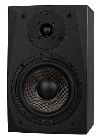
Conventional Two-Way Bi-Amplifier Loudspeakers Most two-way loudspeakers hold a woofer and a tweeter. The woofer can range for 3 inches to 15 inches in diameter, while the tweeter can be a horn or ribbon or planar design; but most often, the tweeter is a 1-inch dome type. Sadly we run into several big problems. First, the phase relationships are off, as the tweeter's voicecoil does not align with the woofer's. At 3200Hz, the wavelength is only 4.25 inches long, so a two-inch misalignment will cause the two drivers out to be out of phase at that frequency. Second, unlike the woofer, the tweeter is delicate—delicate enough to burn up easily in the presence of low-frequency signal. Where would that low-frequency signal come from? Here are some examples, the tweeter power amplifier loses it solid connection to the interconnect's ground, resulting in a full-power hum at 50Hz or 60Hz reaching the tweeter; the tweeter power amplifier undergoes turn-on or turn-off thumps; and, lastly, the power amplifier blows one fuse, causing a big DC offset. Actually, I can think of a few other minor and major catastrophes, but you get the idea. Without a protecting capacitor in series with the tweeter's voicecoil, the risk of damage is high.
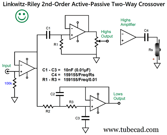
One workaround is to use an active-passive arrangement with 2nd-order crossover slopes.
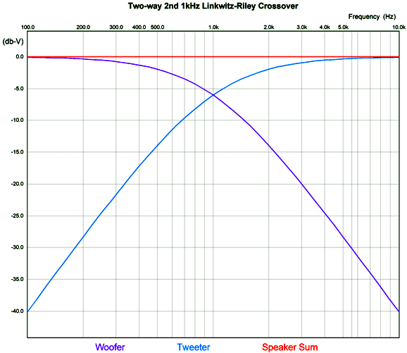
The Linkwitz-Riley 2nd-order (and 4th-order) crossover alignments require that the two outputs be down -6dB at the crossover frequency. The tweeter sees two cascading 1st-order high-pass filters, the first comes the C1 and R1 filter and second from capacitor C4. Both high-pass filters are down 3dB (707.7%) at the crossover frequency, which combines to -6dB (50%) at the tweeter. Important: the tweeter must be wired in anti-phase to the woofer.
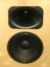
Horn midranges and tweeters present an additional problem: below the horn's natural low-frequency cutoff, the diaphragm is largely unloaded. Thus, at the very least, a 3rd-order high-pass filter is needed, with a 4th-order filter being preferred. With the horn-loaded tweeter, we might be in luck, as the two voicecoils might be physically close to alignment, assuming a smallish woofer, say a 6-inch driver with a shallow cone. In addition, the horn-loaded tweeter will offer screaming more SPL than the woofer. In a normal, un-bi-amped two-way loudspeaker, the solution would be to throw away the excess high-frequency signal with a two-resistor voltage attenuator connected to the tweeter's terminals. In a bi-amped system, in contrast, the added tweeter efficiency is a free bonus, as we can place the attenuation before the tweeter power amplifier, not the tweeter. With this arrangement, with -12dB attenuation, the tweeter amplifier is effectively 16 times more powerful. Mercy! With a horn-loaded midrange-tweeter, the two voicecoils are not likely to coincide, and the lower crossover frequency pretty much demands a 3rd-order crossover.
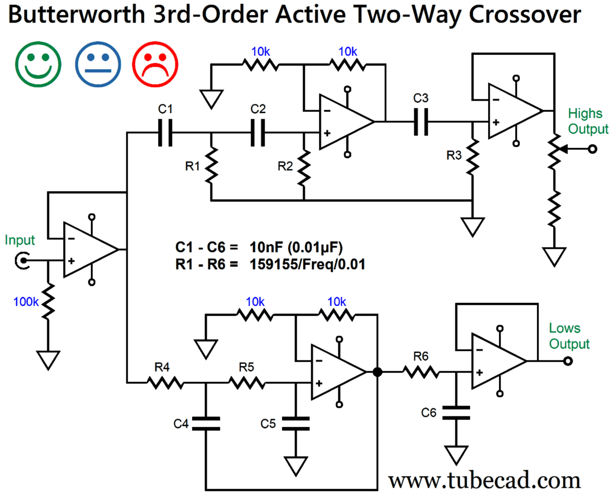
The following active crossover uses the same capacitor throughout, which avoids the hassle of trying to find odd capacitor values. Certain capacitor values are more readily available in 1% tolerances, such as 0.1µF, 33nF, 10nF. Let's use 10nF (0.01µF) as the capacitor value.
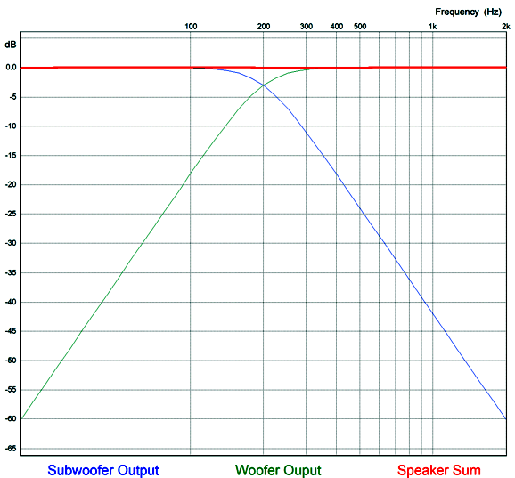
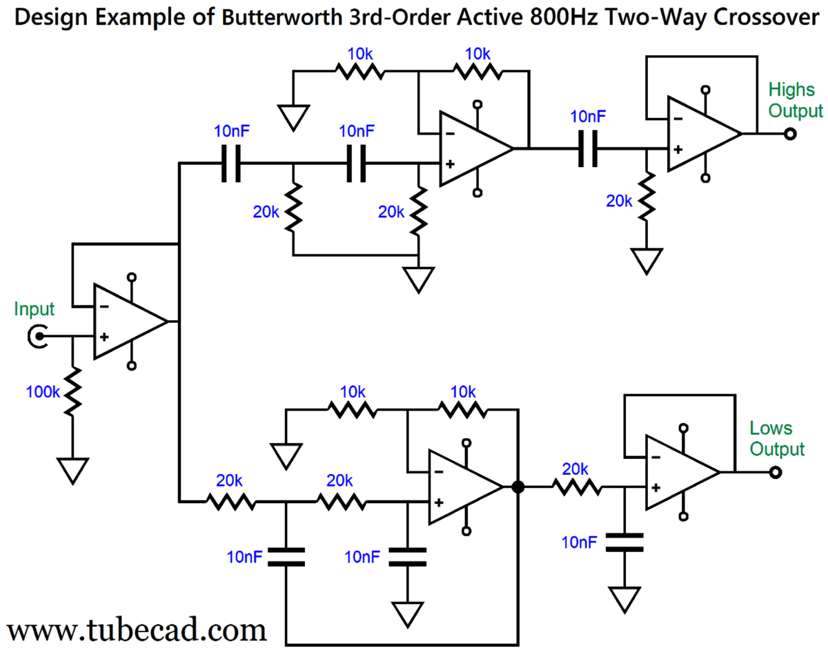
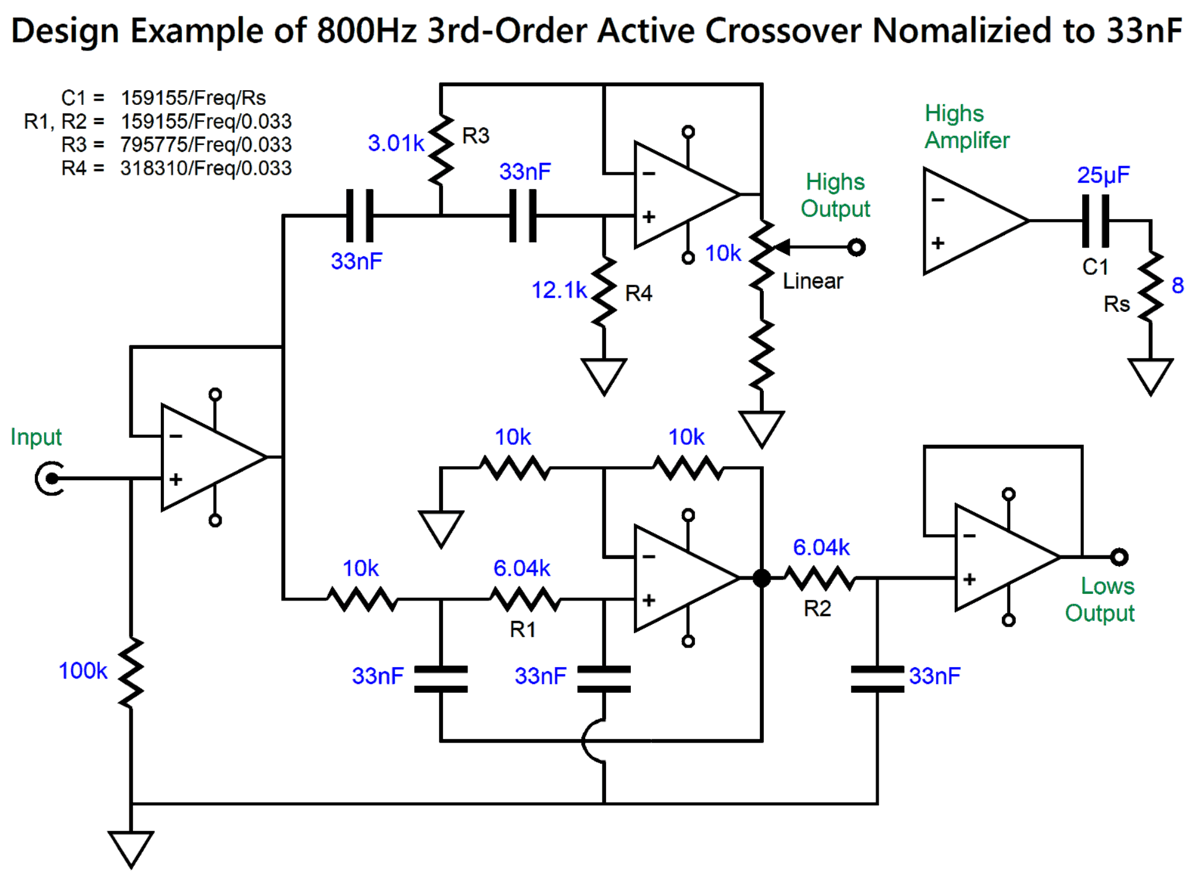
This modification to the classic Salen-Key filter topology allows us to use one capacitor value and one resistor value throughout the circuit. The circuit does, however, introduce a gain of 1:2 (6dB), which might prove a feature in some systems. For example, this active crossover might form the basis of a line-stage amplifier that offers crossover outputs. Only that would be needed are an input-signal selector switch and volume control potentiometer in front of the circuit. The crossover could be as low as 80Hz in system using subwoofers. The three differing faces denote that the crossover might work out perfectly, or might work until something goes wrong, or might never work out due to turn-on and turn-off thumps damaging the delicate tweeter. Interconnects are our enemy. If the crossover is hardwired to the power amplifiers, which in turn are hardwired to the speaker drivers, the tweeter is much safer. Here is a design example for two-way loudspeaker that uses a horn-loaded midrange-tweeter and crossovers at 800Hz.
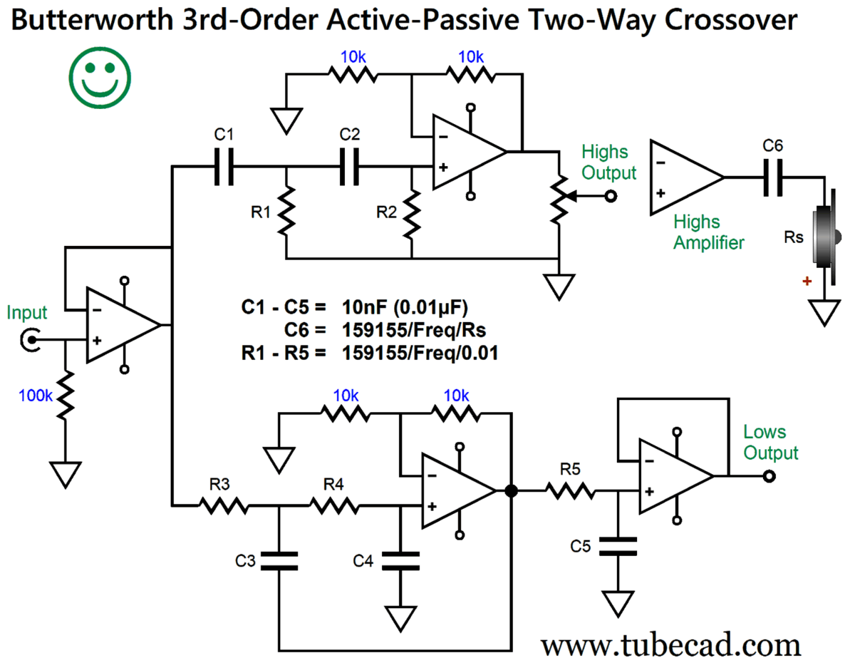
The actual crossover frequency is 796Hz, which is close enough. If the gain proves to be a hassle, we can place a resistor in series with the crossover input. In other words, we can add a two-resistor voltage attenuator. With 3rd-order Butterworth crossover, the tweeter should be wired in inverted phase. I would still use a coupling capacitor in front of the horn-loaded midrange-tweeter, for extra protection, say a 240µF non-polarized electrolytic capacitor bypassed with a high-quality film or PIO capacitor. Alternatively, we can make this added safety capacitor part of the crossover.
Capacitor C6 completes the 3rd-order high-pass filter. I would feel confident that a 1-inch dome tweeter would be safe with this crossover, as capacitor C6 provides protection against 60Hz hum and DC offsets. Note the phase reversal of the tweeter. Both inverting and non-inverting arrangements yield the same frequency response, but the inverted tweeter hook up results in a flatter phase response, only 180 degrees of phase shift from DC to high frequencies, rather than 360 degrees.
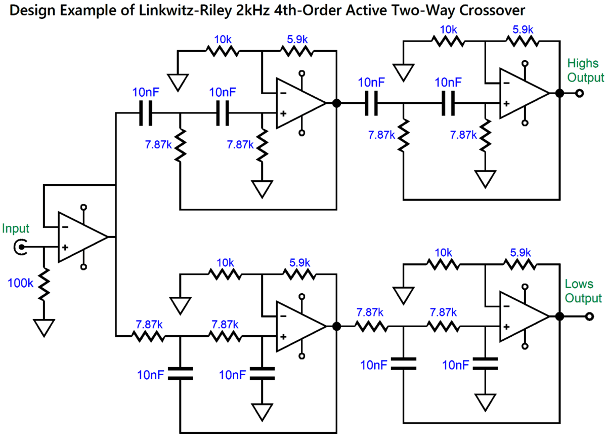
Some like to use a 4th-order crossover in a two-way loudspeaker, as the shape cut-off slopes offer much greater protection to the tweeter and get the sluggish woofer quickly out of the way. The Butterworth alignment produces a 3dB hump at the crossover frequency, so a 4th-order Linkwitz-Riley alignment is needed for a flat frequency response.
Once again, the active crossover has been optimized to use the same capacitor and resistor values throughout, but the gain has increased to 8dB. The tweeter must be wired in phase with the woofer, if the two voicecoils align. If they do not align, experimentation is required. Here is a design example with a relatively low crossover frequency of 2kHz.
The actual crossover frequency is 2022Hz, which, once again, is close enough. Bear in mind that with conventional passive loudspeaker crossovers, the part tolerances are seldom as good as 5%, with 20% being the typical capacitor tolerance. In contrast, this active crossover can easily be filled with 1% parts. Once again, for extra protection I would add a high-quality film or PIO capacitor in series with the tweeter, say 20µF capacitor, which would impose a 1kHz low-pass filter on top of the 4th-order filter. As you might expect, I have made many posts that held active crossover filters. Here is a list that I quickly assembled:
Patreon
Music Recommendation: Dave Stryker, As We Are While Searching for new Stanley Clarke albums, Dave Styker's name surfaced. I had only a vague memory of him being a jazz guitarist. (There so many really good jazz guitarist for someone as old as I am to keep track of all of them.) Soon enough, a large array of his albums assemble before my eyes. I noted that his album, As We Are, was with a string quartet. Jazz music has long tradition of adding strings to sweeten the sound, much like thick frosting on a cupcake. But that sort of instrumental overlay is referred to with the phrase, with strings. Adding a string quartet is more like adding lime juice to a mixed drink, serving to add tartness or bitterness, not cloying sugariness. My long-held practice with any new jazz album is to start with the second track. Wow! I was hooked. not only was the album filled with interesting jazz music, it offers that rare sonic treat that is so favored by audiophiles: well recorded background noises that make the recording sound more like a live performance.
Once again, Qobuz beats Amazon Music, as they offer the recording in glorious 24-bit, 88.2kHz high-res format, bettering Amazon's 24-bit, 44.1kHz.
//JRB
User Guides for GlassWare Software
For those of you who still have old computers running Windows XP (32-bit) or any other Windows 32-bit OS, I have setup the download availability of my old old standards: Tube CAD, SE Amp CAD, and Audio Gadgets. The downloads are at the GlassWare-Yahoo store and the price is only $9.95 for each program. http://glass-ware.stores.yahoo.net/adsoffromgla.html So many have asked that I had to do it. WARNING: THESE THREE PROGRAMS WILL NOT RUN UNDER VISTA 64-Bit or WINDOWS 7, 8, and 10 if the OS is not 32-bit or if the OS is 64-bit. I do plan on remaking all of these programs into 64-bit versions, but it will be a huge ordeal, as programming requires vast chunks of noise-free time, something very rare with children running about. Ideally, I would love to come out with versions that run on iPads and Android-OS tablets.
|
I know that some readers wish to avoid Patreon, so here is a PayPal donate button instead. Thanks. John Broskie
John Gives
Special Thanks to the Special 80 To all my patrons, all 80 of them, thank you all again. I want to especially thank
All of your support makes a big difference. I would love to arrive at the point where creating my posts was my top priority of the day, not something that I have to steal time from other obligations to do. The more support I get, the higher up these posts move up in deserving attention.
If you have been reading my posts, you know that my lifetime goal is reaching post number one thousand. I have 420 more to go. My second goal is to gather 100 patrons. I have 20 patrons to go. Help me get there.
Only $9.95
The Tube CAD Journal's first companion program, TCJ Filter Design lets you design a filter or crossover (passive, OpAmp or tube) without having to check out thick textbooks from the library and without having to breakout the scientific calculator. This program's goal is to provide a quick and easy display not only of the frequency response, but also of the resistor and capacitor values for a passive and active filters and crossovers. TCJ Filter Design is easy to use, but not lightweight, holding over 60 different filter topologies and up to four filter alignments: While the program's main concern is active filters, solid-state and tube, it also does passive filters. In fact, it can be used to calculate passive crossovers for use with speakers by entering 8 ohms as the terminating resistance. Click on the image below to see the full screen capture.
Tube crossovers are a major part of this program; both buffered and un-buffered tube based filters along with mono-polar and bipolar power supply topologies are covered. Available on a CD-ROM and a downloadable version (4 Megabytes). Download or CD ROM
|
|||


 Click on schematic to see enlargement


| www.tubecad.com Copyright © 1999-2023 GlassWare All Rights Reserved |