| John Broskie's Guide to Tube Circuit Analysis & Design |
30 April 2023 Post Number 581
Active Phase-Flat Crossovers We all know that the simple 1st-order passive crossover offers an output that is phase-flat and flat-frequency, along with present a flat impedance. Yet, most loudspeakers sold do not contain 1st-order crossovers; indeed, other than Vandersteen and old Magnepan speakers, I don't know of any other high-end loudspeakers that use a 1st-order crossover. Why not? Sadly, the 1st-order crossover seldom proves practical, as its gentle roll-off slopes allow too much bass energy to enter the tweeter. Tweeters are fragile and audiophiles listen loudly.
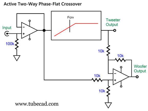
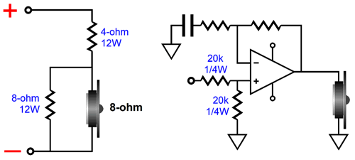
This 1st-order limitation is why I so like the idea of using two identical fullrange drivers with a 1st-order crossover (either active or passive), as this arrangement ensures that high-frequency driver, a driver identical to the low-frequency driver, will be robust enough to handle the weakly diminished bass signals. This is not a popular idea, however, as the conventional 1-inch dome tweeter and woofer combination is too firmly engraved in the mind of the average speaker buyer for him to accept any deviation from the customary practice. One workaround that could deliver phase-flat output, however, might be to use an active asymmetrical phase-flat active crossover, which is based on a differential amplifier circuit to produce the low-pass output signal.
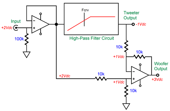
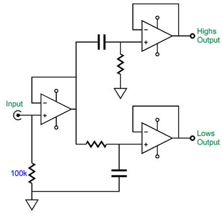
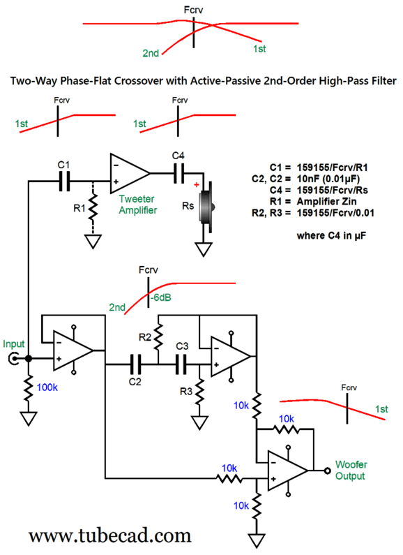
The input OpAmp is only needed to buffer the input signal. (If the signal source already provides a low-enough output impedance, we can eliminate the input OpAmp from the signal path). The box encloses the high-pass filter, which can be 1st-order, 2nd-order, 3rd-order… and can be any filter alignment we desire, such as Bessel, Butterworth, Caussian, Linkwitz-Riley. The differential amplifier performs a miracle: it delivers the needed complementary signal to the woofer that will sum with the tweeter's output to create a phase-flat, frequency-flat sound at our ears. The way it works is actually simple enough. The signal leaving the input buffer encounters the two-resistor voltage divider, which halves the full-range input signal at the differential amplifier's non-inverting input. This -6dB attenuated signal must be matched at the OpAmp's inverting input, as that is what an OpAmp does; an OpAmp strives to maintain the exact same signal at both its inputs, using all its considerable open-loop gain to create the equal signals. The output signal for the tweeter amplifier and output signal for the woofer amplifier meet at the inverting input through the two equal-valued resistors; thus, their signal sum must equal the same signal at the non-inverting input, which is only attenuated by -6dB, but otherwise identical to the signal source signal. In other words, the differential amplifier creates the needed complementary signal for the woofer. Well, the sound from tweeter and woofer will sum in the air in much the same way as the two 10k resistors sum the electrical signals, resulting in a phase-flat and frequency-flat sound. (Of course, this assumes that the speaker drivers are equal to the two resistors in being phase and frequency flat. Good luck with reality.) A quick way to gain some understanding on how the differential amplifier creates the desired complementary signal for the woofer is to think in terms of DC voltages.
The input signal is +2v, but the high-pass filter puts out -1Vdc. The differential amplifier delivers 3Vdc at its output so that both of the OpAmp's signal inputs see the same 1Vdc voltage. Well, -1V added to 3V equals 2V, which was the original input signal. If the high-pass filter puts out +1Vdc, the differential amplifier would also put out +1Vdc, as the two outputs would sum to 2Vdc. Amazingly enough, the differential performs the same feat of magic with AC signals. If the high-pass filter is 1st-order, the output signal for the woofer amplifier will also be 1st-order, which if nothing else, saves us the cost of one tight-tolerance capacitor. In other words, the two 1st-order outputs will be identical to that of the following crossover.
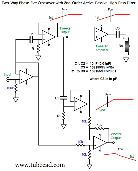
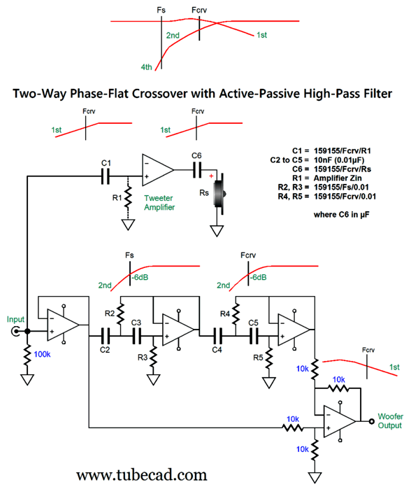
If the high-pass filter is NOT 1st-order, then the woofer amplifier signal will be asymmetrical relative to the tweeter amplifier signal. Okay, that is enough explication, so here is a design that uses an active-passive high-pass filter for the tweeter.
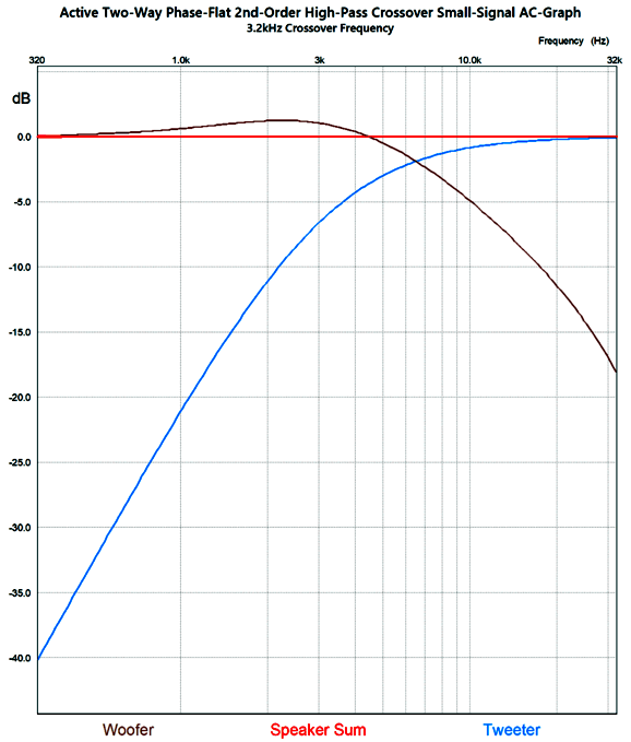
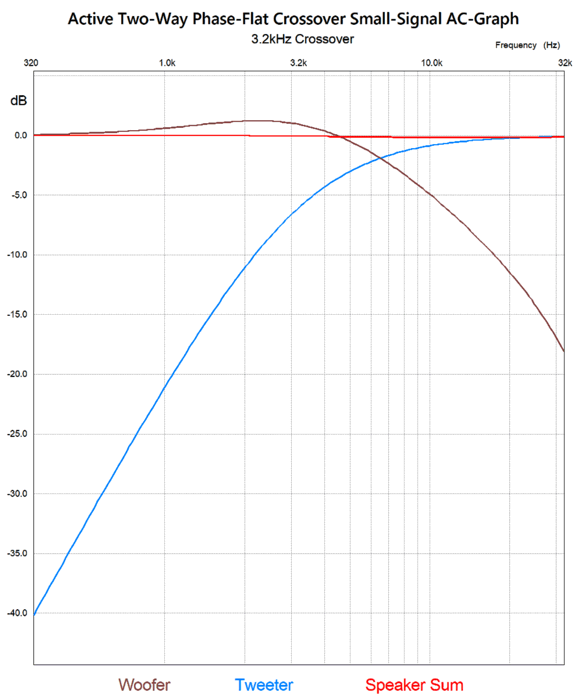
The tweeter is protected by the 2nd-order high-pass filtering and by the coupling capacitor between it and the amplifier's output. (Connected directly, the tweeter might be taken out by 60Hz hum or turn-on and turn-off output thumps from the power amplifier.) Here is the SPICE-generated frequency plotlines for a 3.2kHz crossover.
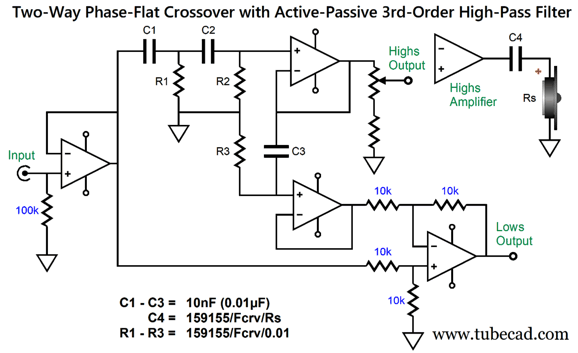
Note that the signal for the tweeter is down -6dB at the crossover frequency, which implies a Q of 0.5, the same as the Linkwitz-Riley alignment. The woofer signal, in contrast, is up 0.95dB at this frequency and its fall off slope is 1st-order. The shallow slope argues for a fullrange driver rather than the usual woofer. In addition, the woofer and tweeter voicecoils should be close to physical alignment and the two driver centers should be physically close. If we desire greater protection for the tweeter, we can give it a 3rd-order high-pass filter, which can be made up from the cascade of active 2nd-order and passive 1st-order filters.
The tweeter is down -9dB at the crossover frequency and its low-frequency rolloff is a steep 3rd-order -60dB-per-decade slope that offers wonderful protection to the tweeter. At the same time, the passive crossover capacitor that attaches to the tweeter protects the tweeter from 60Hz hum and turn-off and turn-off thumps from its power amplifier. Okay, are we done? Have we arrived at perfection? No. Of course, not. Let's start with an issue that isn't so much electronic or electro-mechanical, but psychological. Many audiophiles, especially tube-loving audiophiles, hate the idea of their precious audio signal, perfect and pure, traveling through OpAmps, cheap and contemptible. They would sooner pour a $400 bottle of wine through an old garden hose into a Styrofoam cup. Pure tube, pure sound is their motto, while they blithely ignore all the OpAmps already in the signal path, such as those found in the CD player or DAC or streaming music player. Apparently, what cannot be seen, cannot be heard—much like all the house AC wiring inside the walls and above the ceiling and below the floors does NOT count, only the $3,000 power cord does. For this sort of audio purist, the following crossover might prove ideal.
Only the woofer's power amplifier sees OpAmps in its signal path. The tweeter, on the other hand, sees no active crossover whatsoever, as the its input and output coupling capacitors are both passive high-pass filters, which in cascade and tuned to the same transition frequency result in a 2nd-order Linkwitz-Riley alignment, with the tweeter signal being -6dB down at the crossover frequency.
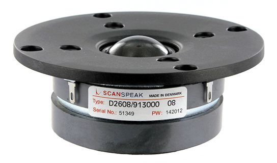
Surely, we are done now, we have arrived, right? No. Remember our goal is both a flat frequency and phase response from the loudspeaker, but speaker drivers are nothing like resistors in terms of impedance, phase, and frequency response. For example, the tweeter's own intrinsic resonant frequency, usually between 400Hz to 1.5kHz, makes the tweeter behave as if it contained its own 2nd-order high-pass filter. An example tweeter is the highly–esteemed Scan-Speak D2608/913000 dome tweeter.
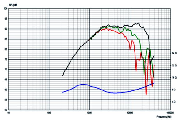
The tweeter's resonance frequency (Fs) is 700Hz; and its Qt is 0.29, which means that the resonance is highly damped. Here is its frequency and impedance plotlines.
Note the steep falloff below 2kHz. This is a problem, as the crossover assumes a flat frequency response equal to the woofer's at low frequencies. In addition, the woofer also brings its own implicit 2nd-order high-pass filter due to its own free-air resonant frequency. Even if that Fs frequency is low as 30Hz, it will rise to a higher frequency due to the speaker enclosure. For example, a woofer with 30Hz Fs might develop an 80Hz resonant frequency (Fc) when loaded by a sealed speaker cabinet. My workaround starts by taking the whole picture in to account and ends by inventing a phase-flat crossover that includes the "hidden" high-pass 2nd-order filters in its design.
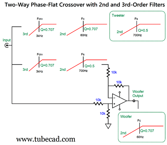
High-pass filters are used throughout. This crossover incorporates the tweeter's resonant frequency in the signal that the differential amplifier must compensate for to deliver a phase and frequency flat summed output at our ears. It ignores the woofer's Fc resonant frequency in its enclosure, based on the assumption that implicit Fc 2nd-order high-pass filter is far enough away from the crossover frequency that we can ignore it. What if we choose not to ignore it? Here is the design overview of an active crossover that includes Fc.
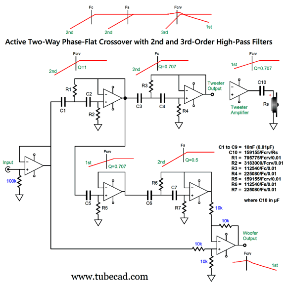
The woofer and tweeter effectively contian their own 2nd-order high-pass filters in their resonant frequencies, Fc and Fs respectively. The 3rd-order crossover frequency of 3kHz is perhaps a tad too high, but this is only a design example. In addition, the tweeter sees the 2nd-order high-pass filter tuned the woofer's resonant frequency (Fc) in its cabinet. (If the woofer is used in a bass reflex enclosure, the 2nd-order high-pass filter must be raised to 4th-order.) Thus, below 60Hz, the tweeter sees 5th-order high-pass filtering, which adds further protection. The differential amplifier provides the needed signal for the woofer amplifier that will ensure both a flat frequency and phase response for the loudspeaker. Here is how we translate this overview into a usable design.
The tweeter gets a coupling capacitor that forms part of the 3rd-order Butterworth high-pass filter. Six OpAmps are needed (or three dual OpAmps) per channel. The same capacitor value can be used throughout the active portion of the crossover. Okay, we have actually arrived. This comprehensive active/passive two-way crossover allows us to have just about everything we desire from a small two-way loudspeaker.
IMPORTANT TIP: when actually building such a complex active crossover, the best path to follow is to first plug in slow OpAmps, such as the LM741 and MC1458CP1, as we want to be sure the active crossover layout is correct, which we might not be able to determine with squirrelly ultra-fast OpAmps. In other words, start slow and move up in speed until instability arises.
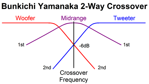
2.5-Way Active Phase-Flat Crossovers No doubt, you have heard of two-way and three-way loudspeakers, but it is unlikely that you have heard of a 2.5-way speaker. There's a good reason for this: they do not exist, as you cannot have a half of speaker driver—well, at least not one that functions. So what do I mean by 2.5? The Bunkichi-Yamanaka phase-flat passive crossover from the late 1960s, which I covered in post 475 and post 544, uses three drivers to create a two-way loudspeaker. The way it works is fascinating. The woofer and tweeter share the same crossover frequency, seeing what is effectively a 2nd-order Linkwitz-Riley crossover, but unlike the Linkwitz-Riley crossover both drivers are wired in phase; the Linkwitz-Riley crossover requires that one driver's phase be flipped, lest a huge suck-out occur at the crossover frequency.
In the Bunkichi-Yamanaka phase-flat passive crossover, this resulting notch in the frequency response is required, but it filled in with a "filler" driver, which sees a bandpass filter with 1st-order slopes.
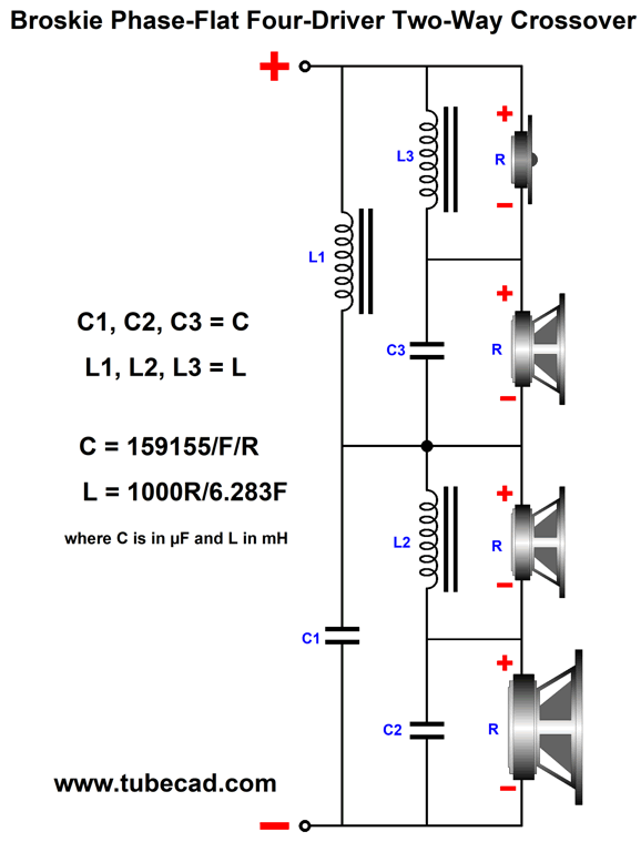
So, is this a two-way or a three-way crossover? Because there's only one crossover frequency, some will argue that it is a two-way. Because there's three drivers, others will argue that it is a three-way crossover. I am willing to split the difference and call it a 2.5-way crossover. In post 544, I revealed a four-driver, phase-flat, two-way crossover that I invented.
Is this a four-way loudspeaker or a two-way crossover? If we split the difference, we get a "three-way" label, which I deem ridiculous. Okay, enough with terminological niceties, let's move on to how to implement a Bunkichi-Yamanaka phase-flat crossover actively and with only two amplifiers.
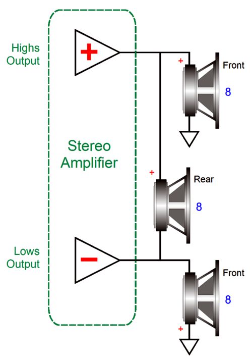
In my last post, we saw how two power amplifiers could drive two front-firing drivers in a bi-amp arrangement, while a single rear driver was driven in a special bridge-amplifier arrangement.
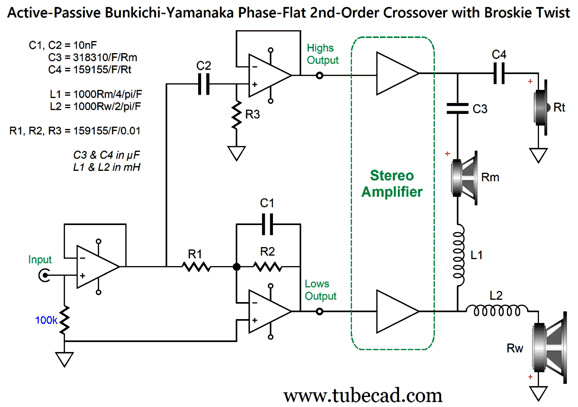
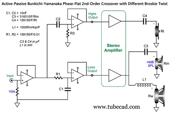
The active crossover filters used are 1st-order and the rear-firing fullrange sees the entire audio bandwidth, in spite of the low-pass and high-pass filters. Well, we can take this arrangement and add some passive crossover parts to create an active/passive Bunkichi-Yamanaka phase-flat crossover.
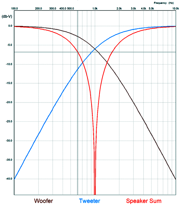
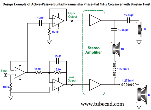
Note the phase relationships throughout. The active low-pass filter inverts the signal, which the bottom power amplifier relays to the woofer, which must be wired in anti-phase. Two anti-phases in series make an in-phase signal. Both the filler driver (might be a midrange or fullrange) and tweeter are wired in phase. Capacitor C4 completes the 2nd-order high-pass filter with a Q of 0.5 for the tweeter and provides added protection to the tweeter. Likewise, inductor L2 completes the 2nd-order low-pass filter with a Q of 0.5 for the woofer. By the way, since the woofer already presents a series inductance, Le, we can subtract Le from the calculated inductor for L2. In fact, if the Le is high enough, we might not need any inductor. (The same holds true for L1 and the filler driver's inductance.) Here is a design example with a crossover frequency of 1kHz.
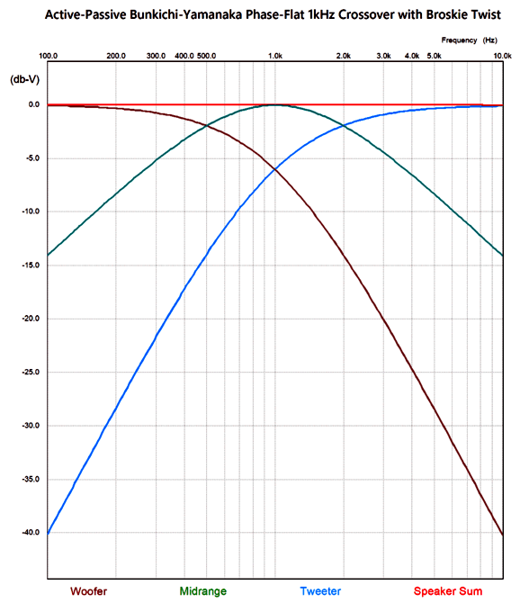
Here is the graph for a 1kHz crossover.
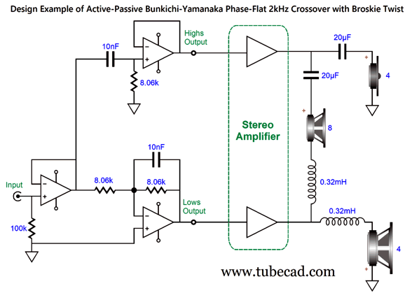
Returning to the schematic, both the woofer and tweeter are 8-ohm drivers, while the filler driver is 16 ohms. With this arrangement, both power amplifiers "believe" they are driving 8-ohm loads. Since our selection of fullrange and midrange drivers in 16 ohms is so narrow, we could use an 8-ohm filler driver instead, along with the required change in C3 and L1 values. The power amplifiers, however, would see a dip in load impedance to 5.33 ohms at the crossover frequency. One workaround would be to use 4-ohm woofers and tweeters with an 8-ohm filler driver.
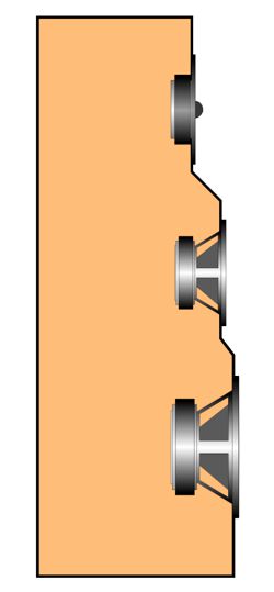
This time, I rounded the crossover part values to the nearest available values. As far as both power amplifiers are concerned, the load impedance is 4ohms. Of course, if we are willing to let the power amplifiers see a non-flat load, we can use other dissimilar driver impedances. What is critical, however, is that the three voicecoils align, which won't be easy. One workaround is to build what has been described as the pregnant kangaroo enclosure, where the woofer protrudes out ahead of the filler driver, which in turn protrudes outs from the tweeter.
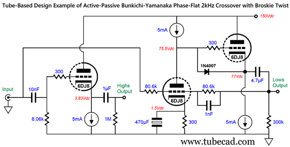
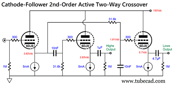
How can we translate the OpAmp-based active portion of this crossover into tubes? Here is how.
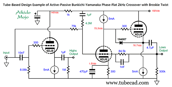
The leftmost triode is configured as a cathode follower with a 1st-order high-pass filter at its input. The remaining two triodes form an inverting amplifier with a built-in low-pass filter in its negative-feedback loop. We can get extra fancy by injecting some Aikido mojo.
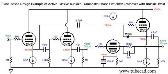
(In SPICE simulations, the feedback resistor needed to be increased to 84.5k to realize the 2kHz turnover frequency.) The assumption behind this circuit is that the signal source, say a line-stage amplifier or a music streamer or DAC, offers a low output impedance. A passive line-stage with a 50K volume potentiometer will not cut it, nor will a wimpy tube-based line-stage amplifier, for example an SRPP-based or grounded-cathode amplifier based design. Okay, what if the signal source's output impedance is high or varying? In this case, we can rescue this tube-based circuit by adding an additional coupling capacitor and doing a little rewiring.
The bass output is inverted, which is essential to making this crossover work. The constant-current sources that see the big voltage drops cannot be made from 30V ICs. The workaround is to use discrete devices, which I will demonstrate in the following section. What sort of an evaluation should we give this active/passive realization of the Bunkichi-Yamanaka phase-flat passive crossover. It's certainly an odd bird in that it combines bi-amp with bridge-amplifier. Like the typical bi-amped setup, we enjoy greater effective sound output from the loudspeaker, as two 25W power amplifiers can play as loudly as single 100W power amplifier. This is possible due to the active crossover filters cutting the audio bandwidth in half. For example, the 25W bass amplifier can put out 20Vpk at 60Hz, while the 25W highs amplifier puts out 20Vpk at 6kHz. In contrast, a single 100W would have to combine these two peak voltages and create a peak voltage swing of 40V, which is the 100W amplifier limit. At the crossover frequency, both amplifier outputs are down by -3dB, which equal 14.14Vpk with a 25W amplifier. Since the outputs are out of phase, the filler driver sees 28.28Vpk, which translates into 25W with a 16-ohm filler driver. The passive crossover parts are a bit of a pain, but the tweeter capacitor add safety and the two inductors can contain the woofer and filler driver own internal inductance (Le), making their values smaller. Overall, I think this arrangement might prove worth the effort, as phase-flat with the added safety of 2nd-order slopes are highly desirable attributes. Yet, we do lose one of the great advantages of a bi-amped loudspeaker: namely, the use of a much higher efficiency tweeter. Image a tweeter with an SPL of 94dB used with an 88dB woofer. With a passive crossover, we have no choice but to throw away the 6dB of SPL from the tweeter with a two-resistor attenuator, with each resistor dissipating as much heat as the tweeter.
But with a bi-amped loudspeaker, the attenuator is placed before the tweeter amplifier, which makes the tweeter amplifier effectively four times more powerful. In other words, a 25W amplifier would play just as loudly as a 100W amplifier with -6dB padding network. Here is a workaround that forgoes the bridge-amplifier arrangement, but requires a filler driver that offers 6dB more SPL per watt than the woofer. For example, we could use a 92dB filler driver with an 86dB woofer.
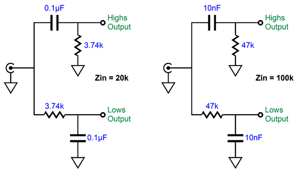
The woofer still sees a 2nd-order low-pass filter at the crossover frequency, and the filler driver still sees a 1st-order bandpass filter tuned to the crossover frequency. No inverting filters are required this time, and all drivers are wired in phase. We can use the tube-based active 1st-order crossover from post 580.
Or, we could forgo active altogether.
Once again, the woofer's inductor, L1, can be partially made up with the woofer's own internal inductance, Le. As far as the bottom amplifier is concerned, it is working into an 8-ohm load, assuming an 8-ohm woofer and filler driver. As far as the top amplifier is concerned, it is working into an 8-ohm load at high frequencies, but a 16-ohm load at the crossover frequency and a very high-ohmage load at low frequencies.
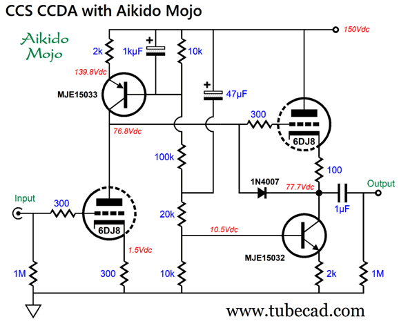
CCS CCDA The CCDA topology consists of a grounded-cathode amplifier in series with a cathode follower, with the first stage's plate resistor equaling the second stage's cathode resistor in resistance. If we replace these resistors with constant-current source, we greatly enhance the circuit's PSRR, as it goes from a miserable 50% power-supply noise leakage down to only 1/mu leakage, where mu is the triode's amplification factor. We can actually improve the PSRR further by incorporating some Aikido mojo.
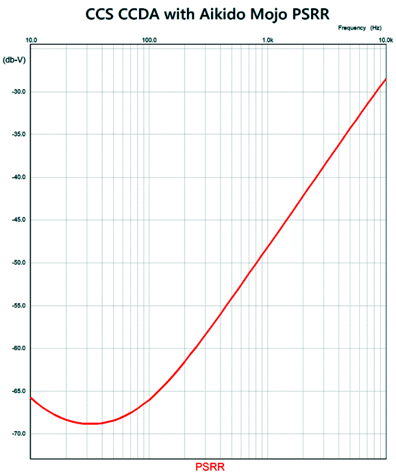
The transistors are 250V devices in the TO-220 package. The PNP transistor (MJE15033) receives a double filtered bias voltage, while the NPN transistor (MJE15032) purposely sees a third of the power-supply noise at its base. Why? The 6DJ8-based cathode follower delivers an output impedance of about 100 ohms, which added to the 100-ohm cathode resistor equals 200 ohms. The MJE15032's emitter resistor (2k) is ten times higher in resistance, so it needs to experience ten times more power-supply noise than the mu of the 6DJ8, about 30, which explains the one-third ratio of power-supply noise for the base. If the emitter resistor was only 200 ohms in value, the base would only need to see 1/30th of the power-supply noise. The circuit delivers a gain roughly equal to the triode's mu, in this example, 30. In addition, its distortion is very low. This circuit can easily be converted into a plate-follower circuit with the addition of two negative feedback resistors. If we strive for unity-gain, the output impedance will roughly equal 200/mu, or 6.7 ohms. In addition, the PSRR will also improve. Here is the PSRR graph for the circuit as it is, with no negative feedback loop.
At 100Hz, the PSRR is better than -65dB, which is excellent, as this is simply the base PSRR, which can be further improved by using either an RC filter or a regulator on the B+ voltage.
Music Recommendation: Golijov Compositions I first heard Golijov's music when his opera, Ainadamar, appeared on the DG label about twenty years ago. I bought the CD based on seeing Dawn Upshaw highlighted as the starring singer. (The lady can sing.) The opera is loosely based on the death of the gay and communist poet, Federico García Lorca, who might have been killed by fascists during the Spanish civil war (no one knows for sure who did it).
I have a hard time listening to any opera all the way through, and this opera is no exception. Nonetheless, the sound recording is notable. Be sure to listen to the first track, if nothing else; also be sure to have your subwoofers at the ready.
La Pasión según San Marcos (the Passion of St Mark) was written about ten years ago, and it caused a big stir. Why? Well, to start it is a Christian work composed by a Jewish composer. In addition, it it is neither lugubrious nor morbidly depressing. Once again, the cover's bright colors are reflected in the music, which includes drum solos, clapping, shouting, females singing as Jesus. As an audiophile and as fan of Argentina music, I quite like Golijov's music. As a sober lover of classical music, I would bet against his compositions lasting the test of time. Something about his music strikes as being too fascicle and trendy. Nonetheless, all three albums exhibit a first-rate recording, but only Nazareno is available in high-res at Amazon Music and Qubuz.
//JRB
Did you enjoy my post? Do you want to see me make it to post 1,000? If so, think about supporting me at Patreon.
User Guides for GlassWare Software
For those of you who still have old computers running Windows XP (32-bit) or any other Windows 32-bit OS, I have setup the download availability of my old old standards: Tube CAD, SE Amp CAD, and Audio Gadgets. The downloads are at the GlassWare-Yahoo store and the price is only $9.95 for each program. http://glass-ware.stores.yahoo.net/adsoffromgla.html So many have asked that I had to do it. WARNING: THESE THREE PROGRAMS WILL NOT RUN UNDER VISTA 64-Bit or WINDOWS 7, 8, and 10 if the OS is not 32-bit or if it is a 64-bit OS. I do plan on remaking all of these programs into 64-bit versions, but it will be a huge ordeal, as programming requires vast chunks of noise-free time, something very rare with children running about. Ideally, I would love to come out with versions that run on iPads and Android-OS tablets.
|
I know that some readers wish to avoid Patreon, so here is a PayPal button instead. Thanks.
John Broskie
John Gives
Special Thanks to the Special 82 To all my patrons, all 82 of them, thank you all again. I want to especially thank
All of your support makes a big difference. I would love to arrive at the point where creating my posts was my top priority of the day, not something that I have to steal time from other obligations to do. The more support I get, the higher up these posts move up in deserving attention. If you have been reading my posts, you know that my lifetime goal is reaching post number one thousand. I have 419 more to go. My second goal was to gather 1,000 patrons. Well, that no longer seems possible to me, so I will shoot for a mighty 100 instead. Thus, I have just 18 patrons to go. Help me get there. Thanks.
Only $12.95 TCJ My-Stock DB
Version 2 Improvements *User definable Download for www.glass-ware.com
|
|||
| www.tubecad.com Copyright © 1999-2023 GlassWare All Rights Reserved |
