| John Broskie's Guide to Tube Circuit Analysis & Design |
12 January 2024 Post Number 593
ACF/WCF 12Vac: New Revision The key advantage of the 12Vac ACF/WCF is that it can be operated from a lowly wallwart 12Vac power supply; yet it develops a fairly high-voltage B+ for the triodes. Where the typical tube-based line-stage amplifier requires a B+ of 200V to 400V, the ACF/WCF 12Vac can get by with only a raw B+ voltage of 160Vdc to drive both channels.
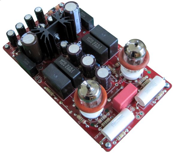
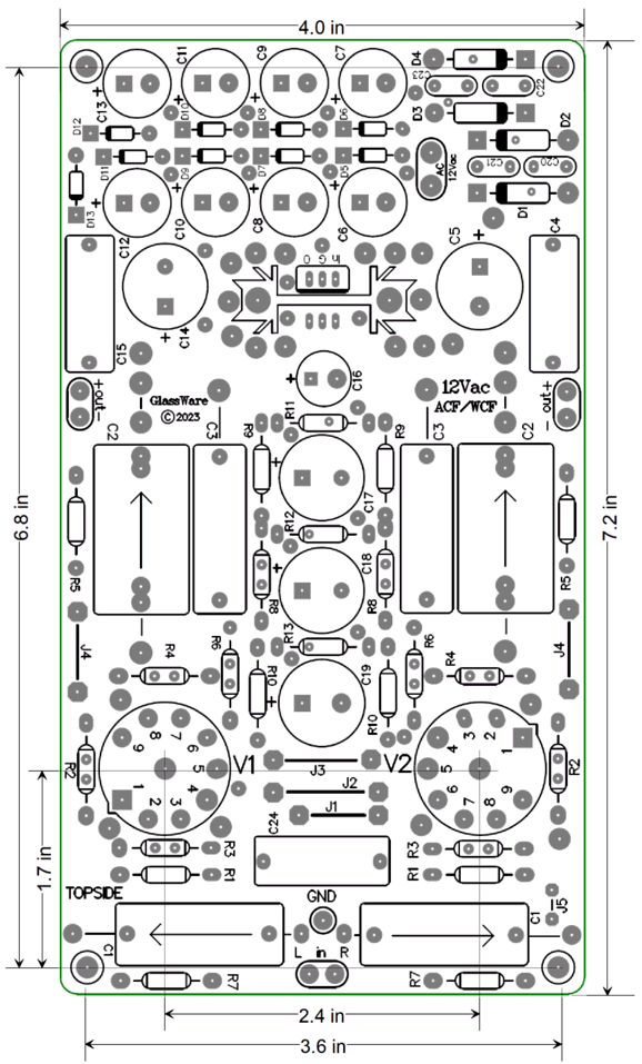
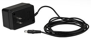
The boards are 4 inches by 7.2 inches, with four mounting holes. The power supply circuitry is internal to the 12Vac ACF/WCF PCB and receives its AC power from an external transformer, usually a 12Vac/24VA wallwart, but a normal power transformer, such as a small toroid, can be used as well.
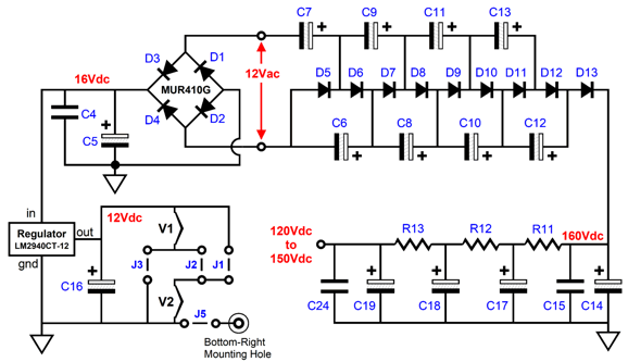
The 12Vac voltage runs through an elaborate 10X voltage-multiplier circuit that develops both the raw high-voltage B+ and the DC heater voltage. The voltage-multiplier creates a raw, no-load, DC voltage of about 160Vdc. The DC power supply for heaters is regulated and delivers 12Vdc up to 1A. The 160Vdc raw DC voltage is perfect for use with two 6DJ8 or 12AU7 tubes.
The tube heaters are placed either in series (with 6CG7 & 6DJ8) or in parallel (with 12AU7, 12BH7, ECC99) and powered by a regulated 12Vdc power supply. The 12Vac transformer used with 6DJ8 or 12AU7 tubes must provide at least 2A of current, which equals a VA rating of 24VA; with 6CG7, 12BH7, and ECC99 tubes, 2.5A current, which equals a VA rating of 30VA. Ideally, a transformer with a good regulation figure (say the 5% a good toroidal transformer would offer) would be used; this is unlikely to be true of a wallwart transformer, however, so some adjustment of the three RC filter resistor values (R11, R12, R13) might be needed.
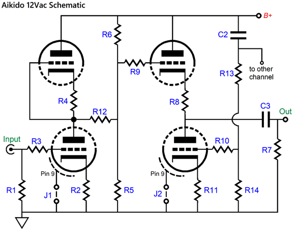
The audio circuitry is almost identical to the old ACF 12Vac, but differs in that I added one extra capacitor (C3) and two resistors (R10) to the PCB. In the old version, both channels shared one C3 capacitor; now, each gets its own C3 capacitor.
The Aikido cathode follower (ACF) buffer circuit provides a gain roughly equal to unity, low distortion, low output impedance, and stellar PSRR (power supply rejection ratio)—all without the use of a negative feedback loop. Note how, in the ACF configuration, resistor R10 has been replaced by a jumper wire. If we do use resistor R10, the circuit transforms into a White cathode follower.
The White cathode follower is a unity-gain push-pull power buffer that, much like the SRPP and SRCFPP , must be optimized for its intended load impedance. It offers twice the potential output voltage swings at roughly half the output impedance of the ACF, but a much poorer PSRR figure, which explains the inclusion of three cascading RC filters. (Note that resistor R9 has been replaced by a jumper wire in this configuration.) The formula for setting R10's value is simple enough: R10 = (2·Rload + rp)/mu + Rk Why would one want to use a White cathode follower? Some power amplifiers, such as the famous Nelson Pass Zen amplifier, present a staggeringly-low input impedance. This White cathode follower can easily drive a 1k load. In fact, with ECC99 tubes, we might be able to drive 600-ohm headphones. The formula for the output coupling capacitor is also simple: C2 = 159155/Rload/Freq where C is in µF, and "Freq" is the low-frequency cutoff. For example, for a 20Hz low-frequency and a 1k external load impedance, use an 8.2µF coupling capacitor (I would use 10µF). How do we find the triode's plate resistance (rp)? The tube manual will not help that much, as rp varies with plate voltage and cathode current flow. Here is a list for the following tubes in the White cathode follower configuration with a RC filtered B+ voltage of 130Vdc.
Sadly, the 12AU7's transconductance is too weak to make a good White cathode follower with such a low B+ voltage. How does the ACF/WCF 12Vac sound? In my test build, I used carbon-film resistors and 6DJ8 tubes. The result was that my Schiit Gungnir revision-B multibit DAC never imaged better, wider, deeper, taller. I have heard the same thing happen in other stereo systems, with far more expensive DACs. Why this is so, I have no idea, as any cross-feed between channels would narrow the stereo image, not expand it. As for harmonic restoration, some, but not much. Perhaps, using some old PIO coupling capacitors or using 12AU7 tubes would give some extra added warmth. The ACF/WCF 12Vac and full-part kit are available now at the GlassWare webstore.
Harmonic Restoration Part Two
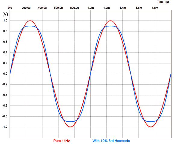
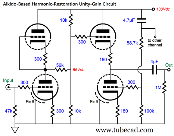
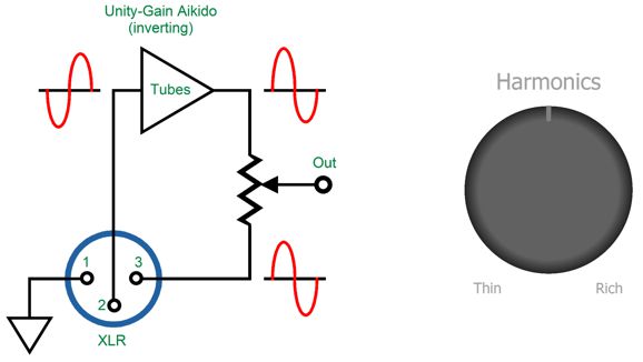
Indeed, if the resistor R12's value is high enough, it can eliminate all the signal gain coming from the input stage; in other words, an input signal of 1V AC goes in and 1V AC goes out, i.e. unity-gain. Yes, I turned an Aikido line-stage amplifier into an inverting unity-gain buffer, while retaining the Aikido's low output impedance—but with an important difference: no negative feedback. No negative feedback means that, although the input signal amplitude remains the same, the harmonic content of the signal is altered, as the triode's harmonic distortion is added, but not subtracted from the output signal. In my last post, I asked a simple question: Is the distortion produced by a triode-based single-ended amplifier a bad thing or a good thing? The answer, of course, is that it depends. Distortion is the departure from the original signal, which can take many forms, such as added power-supply noise, altered frequency bandwidth, clipped waveforms, RFI, and harmonic distortion. Harmonic distortion is the addition of harmonic amplitudes not present in the original signal. For example, if a pure sinewave of 1kHz goes in, then zero harmonic distortion would let only 1kHz go out. In contrast, 1% of 2nd harmonic distortion would add 1% of 2kHz to the output signal. Our ears are quite tolerant of 2nd harmonic distortion, as it sounds natural, since most physical things produce 2nd harmonics when made to vibrate. Even the air in a room adds some 2nd harmonic distortion to a single-frequency soundwave, as the compression and expansion of air molecules is not perfectly balanced (i.e. nonlinear). Even the walls in your listening room impart a slight 2nd harmonic contribution to bass frequencies, as drywall can pull away from the nails attaching them to the frame more easily then they can push against the two-by-four framing. Moreover, most horn loudspeakers exhibit 2nd harmonic distortion due the unequal loading of the diaphragm, resistance on its front and reactance at its back. Harmonic structure is all important to hearing and to recognizing the source of the sound. The exact same note played on different musical instruments sound vastly different, as the instruments impart their own unique harmonic mix to the note. For example, an oboe and a violin playing the same note sound nothing alike. Men and women opera singers sound entirely different when singing the same notes—even old historical recordings of castrato male singers sound nothing like women. Electronic audio circuits also pass on extra harmonic content. Of course, they add more than just the 2nd harmonic, but higher harmonics and different amounts of each harmonic as well. Our ears dislike the addition of odd harmonics, as the 3rd, 5th, 7th, 9th… distortion harmonics sound to us screechy and brittle and discordant, with the exception of 3rd harmonic distortion which sounds like compression, which it in fact is. I refer to the 3rd harmonic as the dead-hand sonic signature.
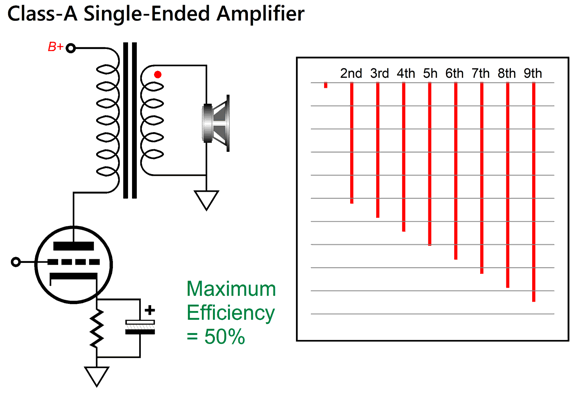
Can't you just hear the oppressive compression? The highpoints crushed and the midpoints made bulbous. A few power amplifiers sound sweet to our ears. For example, a well-designed single-ended amplifier (or power buffer) offers a lovely linear cascade of harmonics.
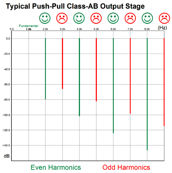
In contrast, a well-designed push-pull amplifier or buffer presents a jagged array of harmonic, as the even-order harmonics tend to cancel out, leaving only the odd harmonics. Indeed, the better the match between output devices, the greater the attenuation of even-ordered harmonics. (This is something that Circlotron fans never consider, sadly. The great advantage to the Circlotron output stage is that it allows us to use identical output devices, just NPN or just N-channel MOSFETs or just triodes, no mixes of NPN and PNP or N-channel and P-channel; but identical output devices also ensure a greater cancellation of even-order harmonics.)
This sonic signature dominates our electronic existence. So much so that—much like fish oblivious to water—we accept it as normal. Your car, phone, stereo, TV, the music playing in the elevator and supermarket—all exhibits this odd-harmonics-heavy sonic overlay. It is "normal" in the sense of customary or routine, but it is not desirable. "Normal" is a moving target. Recently, I discovered that the rock stars, The Rolling Stones and Elton John, played together in Fort Collins, back in 1975—to boos from the crowd. (I have seen The Stones twice in concert and no one booed.)
As I looked at the photographs, I was startled not to observe any obese fans. Back then, hair was long, but bellies didn't overflow belts; thighs didn't rub together, as chubby teenagers waddled; and those exertions necessary to propagate our species dominated our thoughts. "Normal" back then, was not grossly corpulent; today, it is. Once again, "normal" is not necessarily desirable. "Normal" amplifier sound before the 1960s was tube flavored; before the 1940s, single-ended tube flavored. As "normal" mutates, we get used to it, believing it to be the constant and universal "normal." Almost twenty years ago, back in post number 4, I wrote the following:
(The senior analog-electrical engineer did put some effort into getting tube-sound from his solid-state power amplifier. He was convinced that an output impedance of 2 ohms improved the sound. A decade after our breakfast, the solid-state-loving audiophile joined a group of listeners I had assembled to evaluate a shootout between two high-voltage regulators, one entirely tube-based [a Janus] and one pure solid-state [a PS-1]. The AB-test was held double blind—well, as close as I could manage. He preferred the vacuum-state regulator, while the NOS-WE-300B lover preferred the solid-state regulator. How interesting, how embarrassing.)
Returning to the topic of my modified Aikido 12Vac, I wondered what sort of sonic signature would result from the cascading of my harmonic restoration circuit with another tube-based audio circuit, whose design goal was to add some harmonic restoration. I gave it a try. In other words, I doubled up and doubled down on harmonic restoration. I feared an overly-sweet and excessively-smooth sound, but the result was just more lifelike vocals. I was pleasantly surprised by the result. Thus, I had to grab a pencil and drawing pad and start designing new harmonic-restoration circuits.
Unbalanced Harmonic Restoration Blending
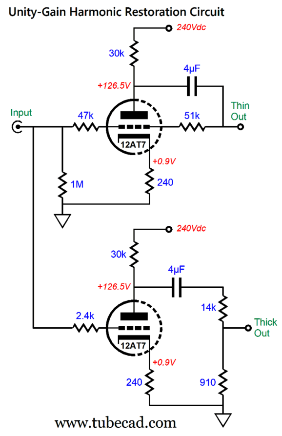
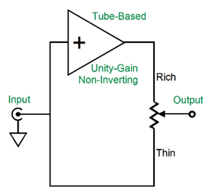
What if no XLR balanced output jacks exist on your audio gear? One design option is to use a twin-triode tube and make two unity-gain circuits, one that employs negative feedback and the other that doesn't. This arrangement would allow us to use an unbalanced input signal from an RCA jack.
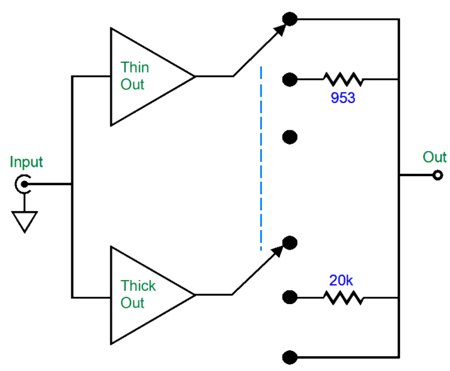
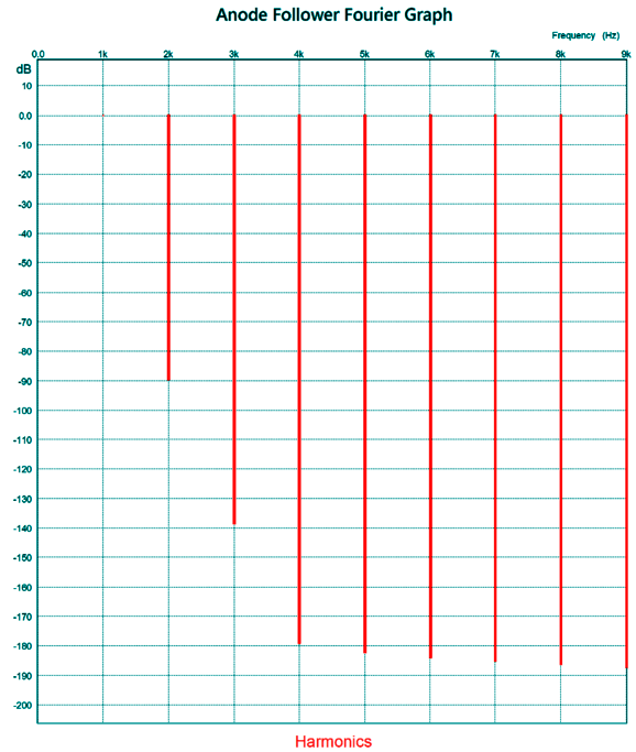
The top circuit is an anode-follower circuit that uses negative feedback to reduce the output gain to unity. The bottom circuit simply feeds its high-gain output signal into a two-resistor voltage divider. Both circuits deliver roughly the same output impedance. An unbalanced input signal is inverted by both tube-based circuits. Next, we replace the blend potentiometer with a three-position rotary switch.
At the top position, we get only a small increase in harmonic enrichment.
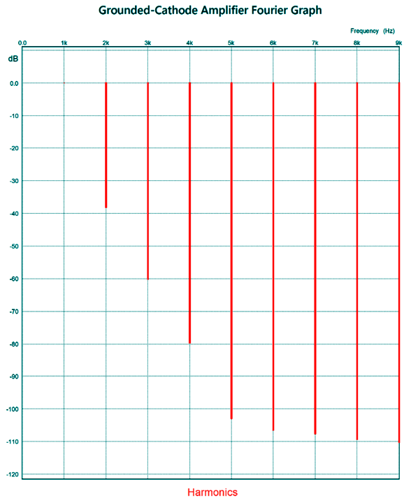
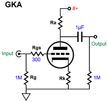
Not much harmonic restoration going on here. Of course, this SPICE-generated graph is overly optimistic, as the SPICE model assumes a 12AT7 triode with a perfectly consistent amplification-factor (mu); reality is not as accommodating. Nonetheless, even if we subtract 20dB from each harmonic, the result is very clean. In contrast, the bottom circuit is a simple grounded-cathode amplifier with no negative feedback. The relatively high value for the grid-stopper resistor is used to equalize the high-frequency bandwidths of both circuits. The two-resistor voltage divider after the output coupling capacitor both attenuates the output signal and burdens the grounded-cathode amplifier, resulting in more distortion.
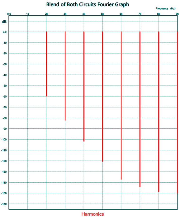
Much juicer. The THD is a tad over 1%. In spite of the negative feedback loop on the anode-follower circuit, the two-resistor voltage-divider delivers an output impedance almost equal to the anode follower. The discrepancy in resistor values in the switching circuit, 953 Ohms versus 20k, is explained by my wanting to only subtract 20dB from the bottom harmonic in the center position, which gives us a nice blend.
Of course, a different mix, i.e. a different ratio could be used. Indeed, I am sure that much experimentation is needed. Another idea I had was that if the tube-based circuit didn't invert the phase, we could use the input signal as the "clean but sterile" reference and the tube circuit as the harmonically rich alternative.
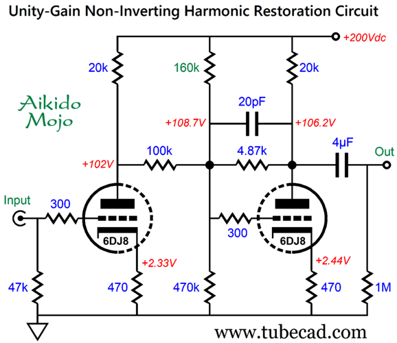
Yes, were back to a potentiometer, but we use a rotary switch instead. More importantly, we need to make a non-inverting tube-based harmonic-restoration circuit. One thought I had was that we could combine the grounded-cathode amplifier with an anode-follower, as both stages invert the phase, thus cancelling. Here is what I came up with:
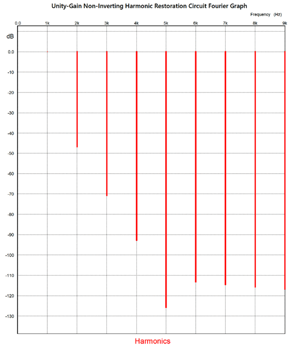
The grounded-cathode amplifier input stage produces a clean output signal, but the anode follower is burdened by too low a resistance negative feedback loop resistor (4.87k), which increases its harmonic contribution.
I love the deep attenuation of the 5th harmonic. Still, the 2nd distortion isn't all that high. This got me thinking that maybe what was needed was just two cascading grounded-cathode amplifiers, with each output working into its own two-resistor voltage divider.
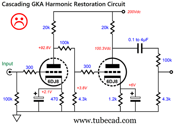
Cascading Grounded-Cathode Amplifiers
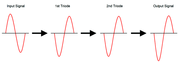
Note that no internal coupling capacitor was used between the two grounded-cathode amplifiers. The second grounded-cathode amplifier's 1.2k cathode resistor absorbs the 3.8V DC offset. (The 1.2k cathode resistor could be replaced by a 5mA constant-current source.) The unhappy face is due to a fundamental problem I noticed. Triodes are easier to turn on than they are to turn off. This is what produces their strong 2nd harmonic distortion signature. But when we cascade two grounded-cathode amplifiers, the second triode undoes some of the 2nd-harmonic enrichment from the first triode.
What we want is for the two triodes to bend in the same direction, both conducting current in phase, not anti-phase.
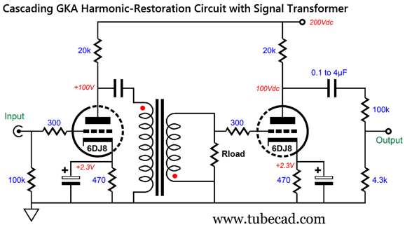
That is what we want, but how do we make it happen? We could use a step-down signal transformer in between grounded-cathode amplifiers, with a 14:1 winding ratio—but with a flipped secondary, which returns the phase to non-inverting.
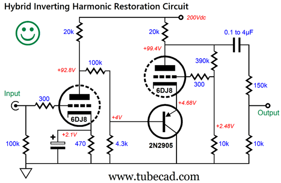
Alas, high-quality signal transformers are both rare and expensive. Well, how about a 50-cent solution: a PNP transistor?
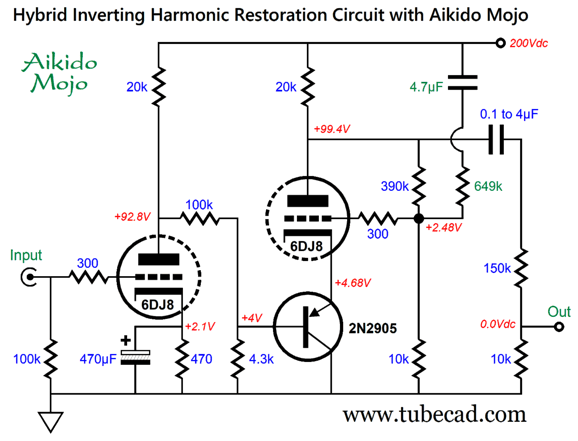
The second stage is a grounded-grid amplifier, not a grounded-cathode amplifier, as the input is at the triode's cathode, not its grid. The grounded-grid amplifier does not invert the phase at its output, so the final phase remains inverted. The 390k and 10k resistors define a mostly DC negative feedback loop that keeps the right triode's plate voltage centered at half the B+ voltage. (It does provide a tiny bit of AC negative feedback.) The 2N2905 PNP transistor is an old workhorse of a transistor. I like its TO-39 package, but other low-power PNP transistors could be used, such as the 2N4403 or MJE210. How much harmonic enrichment can this circuit deliver?
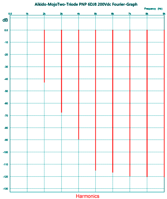
I almost hit my 1% of THD goal. Since I cannot leave any circuit alone, including my own, I sought to inject some Aikido mojo.
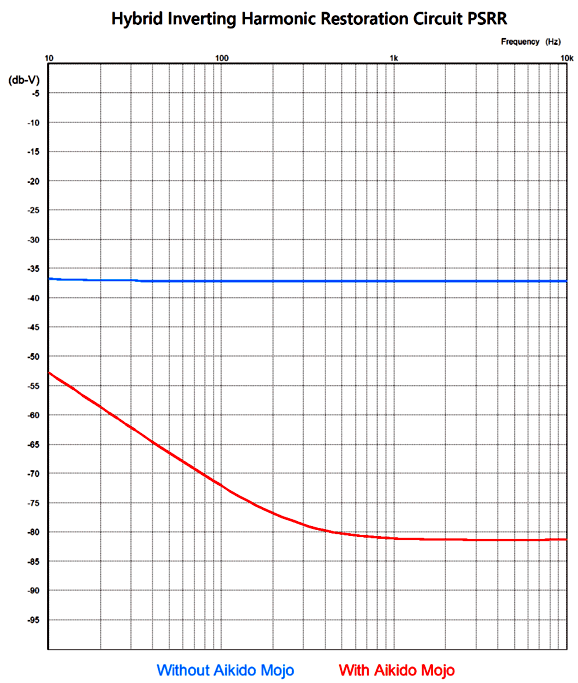
The added capacitor and resistor greatly improve the PSRR.
The Aikido-mojo version is not twice as good; it's 56 times better at 100Hz. In other words, we see 1/56 as much hum signal in its output than the non-Aikido-mojo version. (dBs are a logarithmic scaling, where each 6dB decrease halves the original signal.) Since the second stage, the hybrid grounded-grid amplifier, didn't invert its output phase, the entire circuit is inverting. This means that we are back to needing to use XLR's balanced outputs, if we wish to have a blend potentiometer or rotary switch.
|
I know that some readers wish to avoid Patreon, so here is a PayPal button instead. Thanks.
John Broskie
John Gives
Special Thanks to the Special 93 To all my patrons, all 93 of them, thank you all again. I want to especially thank
I am truly stunned and appreciative of their support. In addition I want to thank the following patrons:
All of your support makes a big difference. I would love to arrive at the point where creating my posts was my top priority of the day, not something that I have to steal time from other obligations to do. The more support I get, the higher up these posts move up in deserving attention. If you have been reading my posts, you know that my lifetime goal is reaching post number one thousand. I have 409 more to go. My second goal was to gather 1,000 patrons. Well, that no longer seems possible to me, so I will shoot for a mighty 100 instead. Thus, I have just 15 patrons to go. Help me get there. Thanks.
Only $12.95 TCJ My-Stock DB
Version 2 Improvements *User definable Download for www.glass-ware.com
|
|||
| www.tubecad.com Copyright © 1999-2024 GlassWare All Rights Reserved |
%20Schematic.png)
%20Schematic.png)

