20 January 2024 Post Number 594

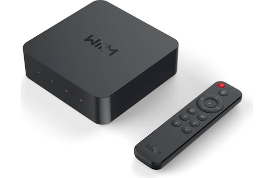
In my recent review of the WiiM Pro Plus streaming DAC, I wrote:
I gave the WiiM Pro Plus own internal DAC a serious listen. Not bad, certainly better than the Chromecast Audio puck, but not great. The Asahi Kasei Microdevices AKM4493SEQ 32-bit DAC chip appears in a few expensive DACs, but I do not believe that the WiiM fully exploits its potential.
I was wrong. The DAC portion of the device sounds far, far better than the Chromecast Audio puck. What changed? I discovered the "DAC Digital Filter Type" section the settings for the WiiM Pro Plus.
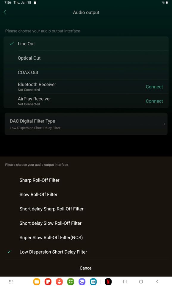
It was set to "Sharp Roll-Off Filter," which turned out to be my least liked setting. The last option, "Low Dispersion Short Delay Filter" turned out to be my favorite. I now concur with all the audio press's glowing reviews of the unit. It really is a sweet deal.

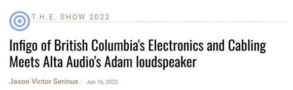
At the Stereophile website, I read discovered class-A, $55,000 a pair, monoblock class-A power amplifiers, the Method 3 made by the Canadian company, Infigo. Quote:
" Due to sliding bias, heat output is claimed to be less than expected. "We use hundreds of transistors," Infigo CEO/founder Hans Looman told Stereophile. "We also use relatively low current feedback to make the amps extremely fast." The amps only consume 35Wpc in idle."
Specifications
Power: 200W RMS Class A in 8 Ohm, 400W RMS Class A in 4 Ohm
Bandwidth: 0Hz - 100kHz (within 0.3 dB)
Input: XLR
Sensitivity: 1.6V RMS
Voltage: AC 120V or 240V selectable, 50 or 60 Hz
To get 200W into an 8-ohm loudspeaker—in any class you choose—requires peak voltage swings of 56.6V and 7.07A of peak current swing; with 4-ohm loudspeaker, 400W requires the same 56.6Vpk but 14.14Apk. Assuming a push-pull output stage and the textbook formulas for class-A operation that set a strict 50% limit to maximum efficiency, we would expect at least 800W of dissipation at idle, not 35W. I visited the Infigo website and saw that they offer a smaller stereo class-A power amplifier that delivers 100W into 8-ohm loads. Moreover, they state that the Method 6 amplifier goes down to 0Hz (i.e. it is a DC amplifier) yet it balances out any DC offset:
"DCBA
A highlight of Infigo Audio amplifiers is the company’s DCBA™ system. DCBA™, or DC Bias Adjustment, balances output DC level without limiting low frequency output. Bass response is tight, powerful, with elimination of phase distortion at lower frequencies thanks to the removal of capacitors in the audio path. The low frequency range extends down to 0 Hz, with a separate protection circuit that disconnects the speakers when the DC level in the signal reaches too high a level."
To my reckoning, this second claim is no less impressive than the first—possibly, more so.
Coupling Capacitors
A DC servo's purpose is to establish a desired DC voltage somewhere within a circuit; in audio circuits, it's usually zero DC volts at the output. In other words, in the absence of any AC audio signal, the output settles to zero volts. Typically, two capacitors are used, one input coupling capacitor and one internal integrator capacitor.
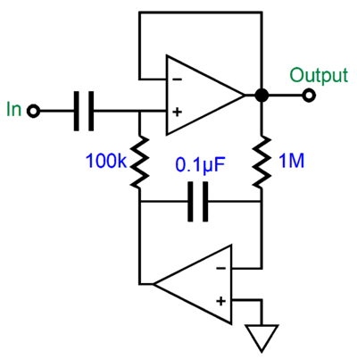
Other servo arrangements feed the correcting DC voltage into the negative-feedback loop; these alternative arrangements often use two capacitors as well. Now, if there's a capacitor inside a circuit that the audio signal passes through, there's probably also an alteration in the low-frequency response. In the circuit shown above, the low-frequency response must ultimately achieve a 2nd-order high-pass filter. The output might begin to slope off at a 1st-order slope, but eventually it will attain a 2nd-order attenuation slope; each capacitor bestows a 1st-order cutoff slope. Sometimes, we can get away with using only one capacitor, such as in the following circuit from post 397.
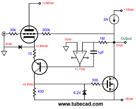
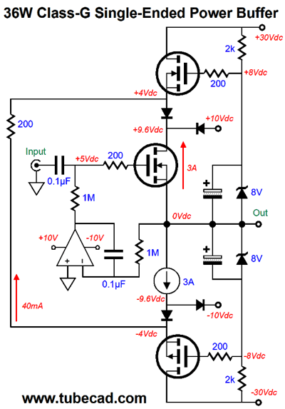
This is a hybrid single-ended power amplifier, with the triode providing the gain and controlling the single-ended MOSFET's output. The OpAmp's output is effectively a ground in terms of AC signals, while it eliminates DC voltages at the output other than 0Vdc. This servo imposes a 1st-order high-pass filter on the output signal from the amplifier. Tucking a DC servo within a circuit does not create an exception to the high-pass filtering action. Here is another hidden DC servo (from post 558) that tugs the output back to zero voltage at idle.
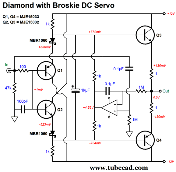
The Broskie DC servo feeds the input signal into the OpAmp's non-inverting input, so the input signal rides on the OpAmp's output along with the DC-correction voltage. In other words, the OpAmp's output no longer presents a virtual ground, nor does it drag down the AC signal presented to the output transistors. It does, however, impose a 1st-order high-pass filtering on the output signal, in spite of the two capacitors used in its construction.
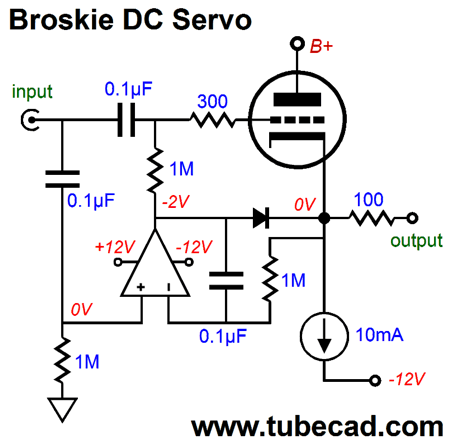
Another example of a single-capacitor DC servo is the tugging version shown in post 591.
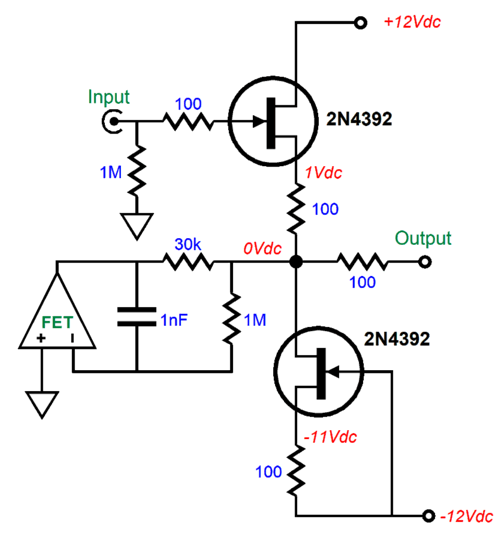
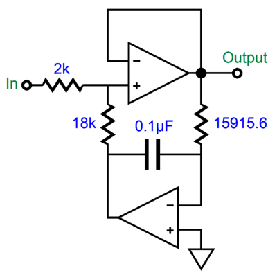
This DC servo tugs the output back to 0Vdc; it, too, imposes a 1st-order high-pass filter on the output. Returning to the version with an input coupling capacitor, what if we replace the input coupling capacitor with a resistor?
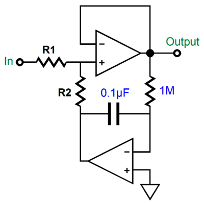
Since we are only left with one capacitor, we still get a 1st-order high-pass filter function from the DC servo. (If the DC servo didn't impose this 1st-order filtering action, then it could not eliminate the DC offset, as it would let the input DC offset pass to the output of the amplifier or buffer.)
The added resistor forms a two-resistor voltage divider with the output resistor on the DC servo, which means that some attenuation of the input signal must result. Why? The DC servo's output is effectively a virtual ground to AC signals. Thus, if both resistors share the same value, we can expect to lose 50% or -6dB of input signal. Interestingly, this two-resistor voltage divider alters the low-frequency transition frequency created by the DC servo.
In the example of the two equal-valued resistors, the low-frequency cutoff frequency would halve. For example, a 20Hz cutoff frequency falls to 10Hz. The larger resistor R1 is relative R2, the closer we get to the DC servo's intrinsic low-frequency cutoff frequency. Conversely, the smaller R1 is to R2, the further down from that intrinsic low-frequency cutoff frequency.
John, what are you talking about? Integrator circuits do not exhibit an intrinsic low-frequency cutoff frequency.
True, but they do exhibit a zero-crossing frequency. An integrator's gain at DC is infinite; at an infinitely high frequency, it's attenuation is infinite. At the frequency implied by the RC time constant resulting from multiplying the capacitance against the resistance, the gain is unity. In SPICE simulation, we see the following graph.
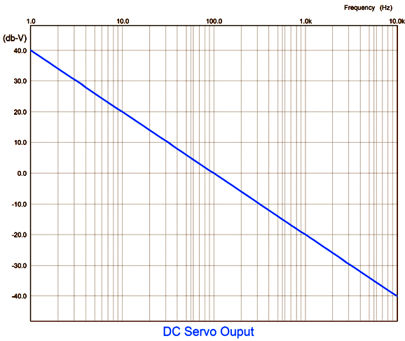
The resistor's value is 1591.6 ohms, while the capacitor's value is 0.1µF, which gives us a transition of 100Hz, based on the following formula:
Frequency = 159155/R/C
Where C is in µF.
What does the frequency response look like from the two-resistor voltage divider's output?
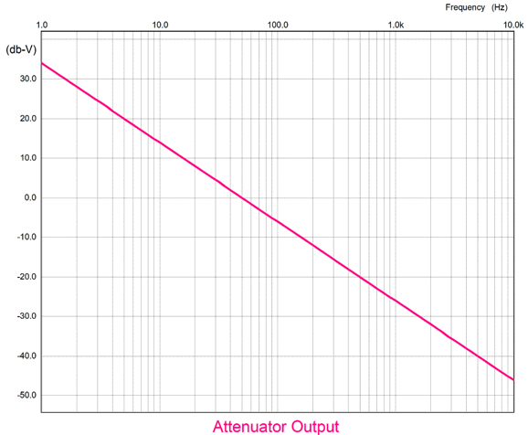
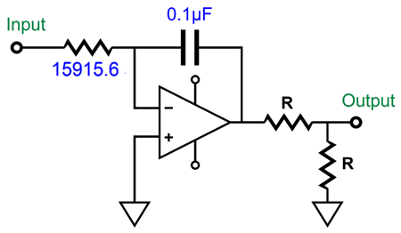
Both attenuator resistors share the same value. Note that the zero crossing now occurs at 50Hz. What if the attenuator resistors differ? The formula is simple enough:
Frequency = Frc x R1/(R1 + R2)
Where R1 is the input resistor and R2 terminates into the DC servo's output. Here is an example:
Substituting the resistor values and the integrator frequency into the formula gives us:
Frequency = 100Hz x 2000/(2000 + 18000) = 10Hz
The input attenuator reducing the DC servo's output by tenfold and decreases the low-frequency cutoff frequency by tenfold. Usually, a 15915.5-ohm resistor would not be used; instead, we can expect a 1M resistor, which pushes the cutoff frequency down to 1.59Hz, which the two-resistor voltage divider then pushes down to 0.159Hz! Since this frequency is so low, many falsely conclude that the DC servo extends down to DC, which would make fabulous advertising copy. It can't. If it did, it could no longer eliminate any DC offset.
Here is how this DC servo could be implemented with a conventional power amplifier.
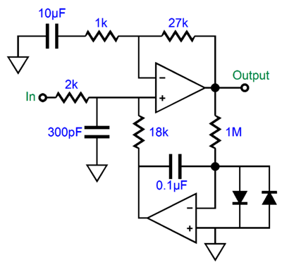
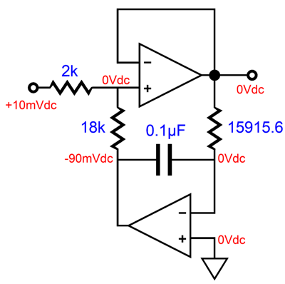
This buffer's input impedance is 20k at audio frequencies, as the DC servo's output is effectively a ground to audio frequencies. Thus, input audio signal will be reduced to 90%, as the two-resistor voltage divider is equal to 18k/(2k + 18k) or 9/10 or 0.9. For DC input signals, the attenuation should be close to infinite—up to a hard limit imposed by the OpAmp used in the DC servo. For example, if the OpAmp runs off ±12Vdc power-supply rails, and if its maximum output voltage swing is ±10Vdc, then the maximum DC offset that can be nulled is ±1.11Vdc. Why? Up to 1.11Vdc of input DC offset, the OpAmp can swing enough inverted voltage to force zero voltage at the resistors connection.
The assumption has been that the signal source is DC-coupled at its output, which is unlikely. Of course, tube-based audio will hold output coupling capacitors, but so will most solid-state signal sources, such as CD players and DACs. In other words, those hidden coupling capacitors will add another 1st-order high-pass filter, making for a final 2nd-order high-pass filter. Is this a problem? Not really. It only is if you believe that bandwidth should extend from DC to light. Back in the 1980s, DC amplifiers were deemed a big feature, mostly in Japan.
The huge problem with DC amplifiers is that DC offsets get multiplied and compound in a long chain of audio devices. A 10mV DC offset leaving a CD player becomes 100mV leaving a DC line-stage amplifier and becomes 3V leaving a DC power amplifier. Even a wee 1mV DC offset grows to 0.3V at the loudspeaker terminals. Had this fad continued, loudspeaker makers would have been forced to use big internal coupling capacitors to protect their woofers. By the way, one surefire way to avoid DC offsets at the output is to use output transformers. Much like a coupling capacitor, a transformer's secondary cannot pass any the DC voltage on the primary.
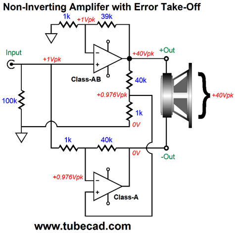
One thought I had was that the error-takeoff scheme from post 467 might sidestep the problem of DC offsets from either present on the input signal or created by the power amplifier.
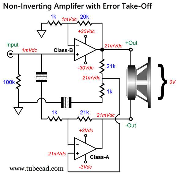
The top power amplifier sees the 1mV of DC offset at its non-inverting input and amplifies it to 21mV at its output. The two-resistor voltage divider at its output is terminated by a large-valued capacitor, let's say 1kµF, so only AC signals are attenuated, not DC voltages. The bottom class-A power amplifier sees the 21mV at its non-inverting input but does not amplify it, as it negative feedback loop resistor string is also terminated by a large-valued capacitor, once again let's say 1kµF, so only AC signals are amplified, not DC voltages; it treats DC input voltages as it were a unity-gain buffer. As far as the loudspeaker is concerned, no net DC voltage appears across its terminals, so zero cone movement results. If the top added its intrinsic DC offset of a few millivolts, it would make no difference as long as the bottom class-A didn't add any DC offset.
Here is the question: since the top is a DC amplifier, meaning that it will amplify input DC voltages, does this entire arrangement count as a DC amplifier? My answer is no. Discuss amongst yourselves.
By the way, the bottom class-A amplifier functions as faux ground, only delivering AC signal at its output when the top amplifier creates distortion. The distortion is attenuated and then amplified at the class-A amplifier's output in phase and in equal magnitude to the class-B amplifier's distortion; effectively, the two in-phase distortion cancel, much as the two identical DC offset voltages cancel. Since the class-B amplifier should produce less than 1% distortion, the bottom class-A amplifier never needs to swing much voltage at its output, which explains its ±3Vdc bipolar power-supply rail voltages.
Okay, does this arrangement also incur a high-pass filtering action? It does, albeit a 1st-order high-pass filtering. With the part values shown and 1kµF terminating capacitors, the -3dB low-frequency cutoff occurs at 0.16Hz. Dang low. Possibly low enough to fool some into believing that it's not there.
Here is the problem with DC voltage: how do you know it exists? For example, let's say that power amplifier produces a +1mV DC offset at it output for 12 hours, then flips to a -1mV DC offset at it output for the next 12 hours, before it flips positive again. Yes, it is creating a one-day squarewave. Do not forget that squarewaves count as AC. Very-low frequencies require very long times to measure. A 0.16Hz sinewave takes 6.25 seconds to complete one cycle. A 0.016Hz sinewave takes over a minute. In other words, if the low-frequency cutoff frequency is low enough, it will probably escape our notice.
Is there no way to implement a DC servo that does not impose a high-pass filter on an amplifier's output?
Some have tried. For example, one high-end audio company uses potentiometers to adjust the DC offset, potentiometers driven by motors that are, in turn, controlled by a DC servo. Alas, this arrangement also creates a high-pass filtering of the input signal. The only way I see this goal happening would be to use an analog-to-digital convertor (ADC) to read the output DC offset only when no audio signal is present and then to send out a correction DC voltage that remains constant until the next signal-free occurrence. Perhaps this might work, but I doubt it. Any shifting in output voltage is an AC signal. If the DC servo constantly reacts to it, it must impart some AC selectivity, allowing audio signals to pass freely, while still cutting off ultra-low-frequency content.
What if cocaine, gambling, heroin, tobacco, smart phones were not addictive? Who wouldn't wish to partake in a little life enhancement, for example, a small dose of heroin and some 1950 jazz LPs, a cigarette or two with friends… Sadly, our existence is not so generous. Does a low-heat high-power class-A amplifier fall into the same category as do sexually wanton virgins or tiny giants or perpetual-motion machines that draw power from a wall socket? Relatively low-heat low-power class-A amplifiers certainly exist, as a 6SN7-based grounded-cathode amplifier counts.
A hundred-watt class-A amplifier, however, is altogether different. The efficiency of class-A single-ended output stages is well established: 50% with an inductive load; 25% with a constant-current source load, less than 10% with a resistive load. A class-A push-pull output stage's theoretical maximum efficiency is also well established: 50% with or without an output transformer.
Class-A is determined by current flow. If a transformerless, push-pull class-A output stage, in either the totem-pole or circlotron arrangement, delivers 100W into an 8-ohm load, then its current flow at idle must at least equal half the peak output current swing, which in this example is 5Apk, so an idle current flow of 2.5A is required. In addition, 100W into an 8-ohm load implies 40Vpk voltage swings. Assuming perfect, lossless output devices and bipolar power supply rail voltages of ±40Vdc, the heat dissipation at idle would be equal to 2.5A against 80V, or 200W, which conforms to the theoretical maximum efficiency of 50%. 200w goes in, but only 100W comes out into the loudspeaker, the other 100W heats your room.
The reason the output devices never cease to conduct current is due to the idle current being so high. Replace the 8-ohm loudspeaker with a 4-ohm speaker and the maximum class-A watts falls to 50W, as thereafter the output devices do turn off. Others argue that class-A only means that the output devices never cease to conduct current. Period. This is a strangely legalistic definition. I have read that for every inch a man is over 5 foot, his odds of being accepted by a professional NBA team double. When we get to 7 foot 3 inches, a lot of compounding doubling has occurred; so the odds have improved by 2 to the 27th power or 134,217,728 times. Add another inch, and his odd double. Well, what if the seven-foot man went to a plastic surgeon and had single triple-D breast implant inserted under his scalp, making him 7-foot, 6-inches tall. Will his odds have improved by 64-fold? I doubt it, although the legalistically inclined might disagree.
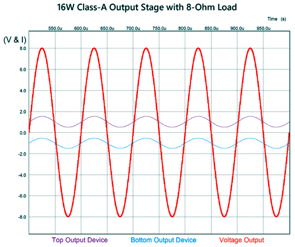
Here is an example of a solid-state output stage whose output transistors never cease to conduct.
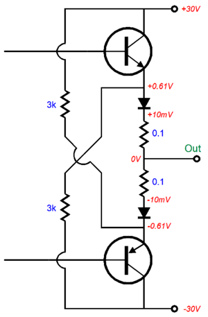
The two output transistors draw only 110mA at idle, but can deliver over 40W into an 8-ohm load. They never stop conducting, even with 1-ohm loads or 0.1-ohm loads; therefore, this is a class-A output stage. Right? If you work for a law firm or marketing department, damn right—it's class-A all the way—in spite of an output stage dissipation of only 6.6W at idle. Others, more sober people, like me, argue that only "meaningful" conduction counts, that only 0.16W of actual class-A watts are delivered into 8 ohms before the output stage enters class-B operation. Who is right? I would let our ears decide—much as I would let actual basketball play decide if top-of-head breast implants add to athletic performance. As far as our ears are concerned, amplifier class of operation only matters if it might predict sonic performance, class-A only serving as a proxy or marker for potentially good sound. Do not forget that bad-sounding class-A amplifiers do exist.
Now things get interesting. What if we create a hybrid amplifier, hybrid not in the sense of mixing vacuum tubes with solid-state devices, but in the sense of mixings amplifier classes, say class-B with class-A. Would such an amplifier count as class-A in the court of audio? For example:
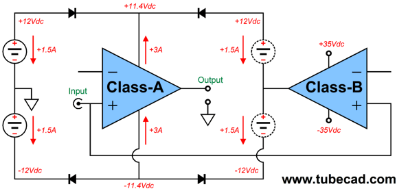
My design appeared in post 449. It is effectively a class-G design that uses three bipolar power supplies, one fixed (on the left and the one not shown that powers the class-B amplifier) and one floating (at the class-B's output). It dissipates 72W at idle, yet can deliver 100W into 8-ohm loads. These are real class-A watts in my mind, as the class-A on the left still runs in class-A at full output. What this topology needs is a snazzy label. Perhaps, class A-BG. If we lower the bipolar power supply on the left from ±12 Vdc down to ±5 Vdc, the class-A amplifier would dissipate only 30W at idle. To get the 100W of output would require raising the fixed bipolar power supply rail voltages (the power supply that feeds the class-B amplifier) to something like ±42 Vdc. A simpler variation would forgo the class-G aspect.
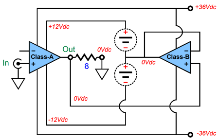
This is an example fothe Super Class-A topology from the 1970s. This designs also delivers 100W into 8-ohm loads (40Vpk and 5Apk), yet the class-A output stage dissipates only 72W at idle. Then there is the possibility of using single-ended/push-pull class-G arrangement. From post 447:
Is this a class-A amplifier? You cannot get much more class-A than a single-ended output stage. Is there only one output device or three? Then there is the famous Quad current-dumping design:
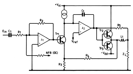
The transistors, Tr2 & Tr3, run in class B, as both are turned off at idle. Amplifier A2 runs at a light class-A idle current, but its job is only to clean up the class-B output stage's mess. And let's not forget Mr. Sandman's class-S designs.
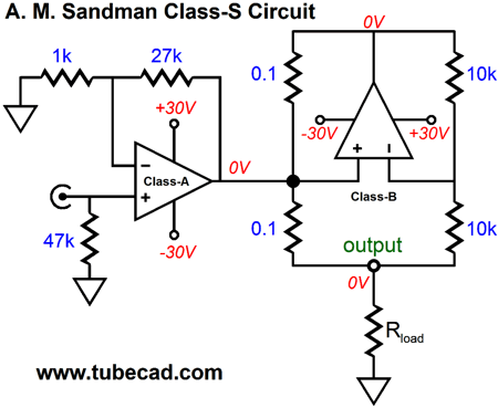
Check out post 284 for an explication of how this circuit works. His early class-S topology also used two power amplifiers.
The loudspeaker never attaches to ground; instead, the class-A amplifier functions as a faux ground. If the class-B amplifier delivers a perfect output, there is no error signal for the class-A amplifier to fix. To see how this arrangement works, let's use a DC offset on the class-B amplifier's output as a form of distortion, which it is, as it is a deviation from the input signal which presented no DC offset.
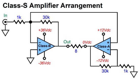
Do not forget that a loudspeaker is a perfectly differential device, as it must see voltage difference across its voicecoil; no difference, no motion. If the class-B amplifier clips, the class-A amplifier can correct this form of distortion—up until the class-A amplifier runs out of potential voltage swing.
Note that the class-A amplifier runs off much lower power-supply rail voltages than the class-B does, yet 100W can be delivered to an 8-ohm loudspeaker. (See post 448 for more details on this arrangement.)
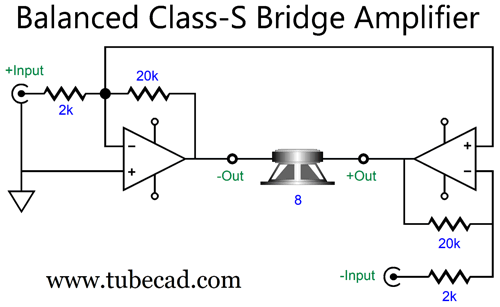
My own contribution to the class-S arrangement appeared in post 575.
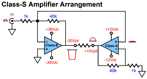
And post 467 showed a class-S amplifier whose faux-ground class-A amplifier inverts the input signal phase with inverting amplifier configuration, but receives a non-inverted signal at its non-inverting input.
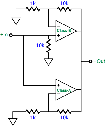
The result is that the class-AB's distortion is presented in-phase and equal in magnitude at the faux-ground amplifier's output, thereby creating a distortion null. Well, my looking at these last two schematics got me thinking, making me wonder if I couldn't further exploit an XLR's balanced output signals. I could.
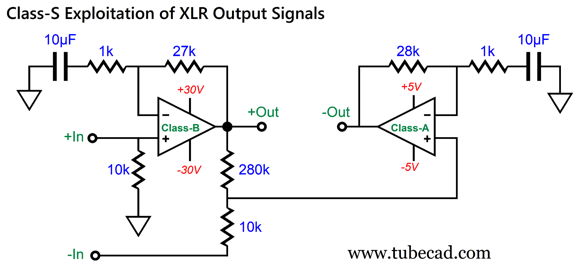
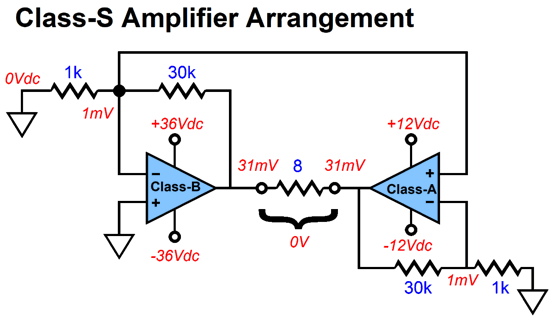
Neither amplifier is in the inverting configuration; both offer a relatively high 10k input impedance. The class-A amplifier on the right still functions as a faux ground in the Sandman class-S way of functioning, only deviating from 0V output to correct the class-B amplifier's errors. Let's use a DC offset voltage to show how the class-S magic works.
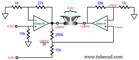
The class-B amplifier puts out a 29mV DC offset The two-resistor voltage divider made up of the 280k and 10k resistors reduce it to 1mV, which the class-A amplifier then treats as an error input signal and amplifies it by (28k + 1k)/1k or 1:29, resulting 29mV at its output. The loudspeaker sees zero difference between the two amplifier outputs, so the DC offsets are ignored. If the DC offset appears only in the input signal to the class-B amplifier, then it would be amplified by the class-B amplifier, and the class-A amplifier nulls the DC offset. More likely, however, the small DC offset would appear at both XLR balanced outputs, resulting in the offset voltage being amplified by the gain of the class-B amplifier and passed on to the loudspeaker. In other words, this arrangement is not a classic balanced differential amplifier, where only differences are amplified. The assumption behind my non-inverting class-S amplifier is that the XLR anti-phase outputs, if summed, will actually cancel.
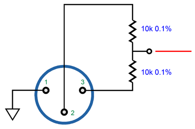
If any signal remains, which includes DC offset voltages, then the outputs are not truly balanced. Sadly, we have botched the beauty of balanced signal transmission. We have needlessly added "ground" to the mix, forcing this awkward third element onto a perfect pairing. Moreover, due to safety concerns, the "ground" prong was added to the power plug. Now "ground" is no longer an individual, isolated thing, unique to each electronic component, but a universal overlay. Unfortunately, much like where strict equality is enforced, where some are more equal than others, some "grounds" are less of a "ground" than other grounds.
In other words, in an optimal balanced system, the signal-source ground does not attach to the receiving-source's ground, except occasionally through a 0.01µf capacitor in series with a 51-ohm resistor; the interconnect's shield attaches only to signal-source's ground; the receiving-source's XLR connector casing is grounded only to the receiving-source's ground, not the interconnect's shield; the two balanced input signals then must pass through two coupling capacitors. This arrangement allows the two separate grounds to live in peace and the balanced signal to travel freely between electronic devices, in spite of huge voltage differences between devices.
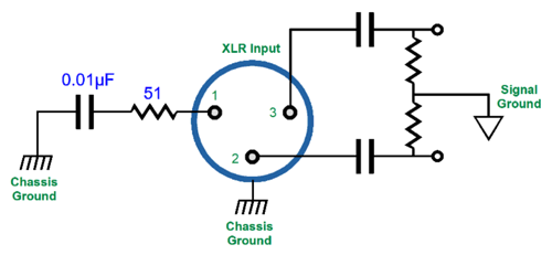
With this arrangement, it doesn't matter if the balanced pair of signals fails to sum to zero, as they will after the two coupling capacitors—but only if the signal source's ground does not attach to the receiving source's ground. For example, if the non-inverted signal from pin-3 peaks at 1.2V relative to pin-1, while the inverted signal from pin-2 only peaks at 1V relative to pin-1, after the two coupling capacitors, both peak at 1.1V relative to the receiving circuit's ground, both sum to zero. Throw a bridging-grounds wire into the mix or a shared connection to the house ground, and the deal is off, as the poor attempt at balanced continues. Another compound power amplifier topology that blurs the distinction between class-A and class-B is the infinite-impedance amplifier.
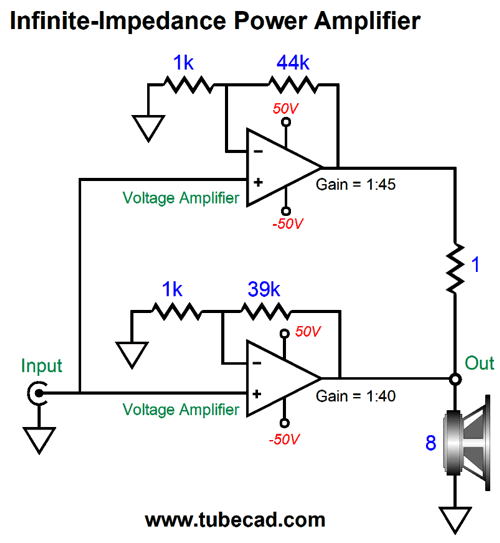
The amplifier on the top does most the work, as it must deliver both voltage and current, whereas the bottom amplifier must only deliver voltage—as long as the top amplifier doesn't add distortion; if it does, the bottom amplifier must deliver enough current to correct the top amplifier's output. Imagine that the top amplifier is class-B, while the bottom amplifier is class-A, but a wimpy class-A, being only class-A into an 80-ohm load, not an 8-ohm load. With an 80-ohm load, the bottom class-A amplifier idle current need only be 0.25A, assuming a push-pull designs; if single-ended, 0.5A of idle will be needed.
This is an amazing topology, but it offers several traps. The first is that, much like a current-output amplifier, this compound infinite-impedance amplifier must be loaded at all times. For example, if no loudspeaker attaches, and 1Vpk of input signal is applied, then both amplifiers must deliver 5Apk of current into the 1-ohm bridging resistor; worse, the bottom amplifier will get far hotter than the top amplifier. Second, the loudspeaker's impedance must be dang flat, not the typical rollercoaster impedance plot. Planar loudspeakers might work best here, but not all, as some use Linkwitz-Riley crossovers whose impedance peak hugely at the crossover frequency.
Ideally, what I want is a marriage between powerful class-B and wimpy class-A, where both work in parallel and share the same signal gain and the same bipolar power supply, yet the class-A amplifier dominates the combined output. I have finally devised a topology that achieves this ideal, but it will have to wait until my next post, as I am at my word and finger limit (I am nearing 5,000 words). Roughly, the concept looks like this:
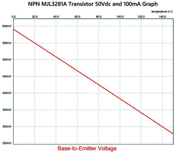
I must say a few words about sliding bias, however, before I sign off. Sliding-bias is a great idea—if you can make it work. Making it work with vacuum tubes is relatively easy, as tubes always run hot and increases in heat do not throw off the grid-to-cathode voltage relationships. In contrast, silicon output devices are extremely sensitive to changes in heat. A transistor's base-to-emitter voltage is a moving target. As the transistor's temperature rises, its base-to-emitter voltage decreases. Thus, dynamically adjusting the needed bias voltage to ensure class-A operation from 1W to 100W is not easy when reproducing music.
With a class-A push-pull power amplifier that slides it bias voltages, both of the output devices (or sets of output devices) must be dynamically adjusted at once. For example, if the idle current is 100mA and the input sees a tone burst that results in 100W of output, the idle current must instantly slide up—at least—to 2.5A (assuming an 8-ohm loudspeaker; 3.535A for 4-ohm loudspeakers). This will make for interesting swings of current through the output devices, although the voltage swings will remain normal. In other words, once the output current swing exceeds the class-A window ( ±200mA), both the top and bottom output devices must instantly soar in current conduction, so the opposite voltage swing can be produced in class-A. If one of the output devices ceases to conduct, while its opposing partner undergoes a torrent of current, the desirable label of "class-A" must be withheld.
I only really knew one song from Marc Cohn, "Walking in Memphis." (I am sure that I am not alone in this.) Somehow, I discovered his 2010 album, Listening Booth 1970, at Amazon Music. The album is a collection of hit songs from the year 1970, and Amazon offered it in 24-bit, 192kHz. In other words, I came for the high resolution, but stayed for the music.
I was 14 in 1970, and I well remember all the songs being played on the radio. As a young music snob, I discounted most of them as fluff. Today, either I am less of a snob or I have come to embrace fluff or, perhaps, good songs simply must await good singers.
Marc Cohn has a wonderfully soulful voice, and his spare arrangements are tasteful. Moreover, he sings the songs, as if he had written them, with conviction and emotion. In fact, I found myself listening as if it were my first time, not my actual hundredth hearing of these hits. A similar feat was accomplished by Bettye LeVette with her album also from 2010, Interpretations: The British Rock Songbook. She sings each song not only as if she wrote it, but as if she actually lived it. After playing a track from her album for a friend, he told me that, in spite of his having heard the original a hundred times, he had no idea the lyrics actually meant something intelligible and heartfelt.

Returning to Marc Cohn, his cover of "Long As I Can See The Light" made me forget Creedence Clearwater Revival's original release. And I found that his cover of "Maybe I Amazed" greatly improved on Sir Paul's original screaming rendition.
Definitely an album worth hearing.
//JRB
Did you enjoy my post? Do you want to see me make it to post 1,000? If so, think about supporting me at Patreon.

  
Just click on any of the above images to download a PDF of the user guides.

For those of you who still have old computers running Windows XP (32-bit) or any other Windows 32-bit OS, I have setup the download availability of my old old standards: Tube CAD, SE Amp CAD, and Audio Gadgets. The downloads are at the GlassWare-Yahoo store and the price is only $9.95 for each program.
http://glass-ware.stores.yahoo.net/adsoffromgla.html
So many have asked that I had to do it.
WARNING: THESE THREE PROGRAMS WILL NOT RUN UNDER VISTA 64-Bit or WINDOWS 7, 8, and 10 if the OS is not 32-bit or if it is a 64-bit OS.
I do plan on remaking all of these programs into 64-bit versions, but it will be a huge ordeal, as programming requires vast chunks of noise-free time, something very rare with children running about. Ideally, I would love to come out with versions that run on iPads and Android-OS tablets.
|


