| John Broskie's Guide to Tube Circuit Analysis & Design |
13 May 2024 Post Number 602
March 199
Now is a good time to thank my Patreon patrons. All my non-Patreon readers should also thank them, for without their support many fewer posts would have been made, with post 600 in the distant future. Thanks Patrons.
Rethinking Digital Volume Controls In addition, our computers allow database searches, which is my favorite feature. Here is a counter example, let's say you own 3,000 LPs, in which ten tracks of the famous Gershwin song, "Summertime," are located. Great! But let's say you wish to play all of them in series. Not so great. First of all, can you actually remember where all ten tracks are held on ten LPs out of 3,000? Well, even if you can remember, do you really want to pull out all ten LPs and run each through the LP ritual of cleaning, static purging, and cueing each one up for playing, and then refiling the record jackets? I don't. In contrast, we can either let our PC search our own digital collection of music or let a music streaming service do the job of searching through its near limitless collection of albums; instantly, all the covers of that song are promptly arrayed, ready for playback. (I just performed this search of my own collection on my PC; almost 50 covers were found. I tried Amazon Music and the list seemingly never ended.) So far, all is good. In my own system, once the analog signal leaves my DAC, it enters my unity-gain, dual-cathode-follower line stage.
Well, more precisely, it enters the source-selector switch and then travels to the ladder stepped attenuator and then to the 12SX7 grids.
The analog signal leaves my DAC is at full volume, so the attenuator is needed—but is it? Why not use the digital attenuator in my PC instead? I could lose the physical attenuator altogether, relying on the PC to reduce the volume via my Samsung tablet that functions as my remote control. Less can be more. I am so, so, so very tempted to rewrite Hamlet’s Soliloquy to be about doing away with the physical attenuator, as so many of the lines could be easily retrofitted to conform to mental anguish audiophiles suffer, with the ending lines resounding our hesitancy:
In sort, should we trust digital attenuation? My previous answer was sometimes but not always. As I saw it, 16-bit data sent to a 24-bit DAC allowed up to -48dB of attenuation without any resolution loss, as the DAC's extra 8 bits would simply allow an 8-bit shift to the right. On the other hand, digitally attenuating 24-bit recordings with a 24-bit DAC must necessarily throw away resolution. My latest thinking is that I was overly pessimistic. Let's start with reality, hard reality. Your 32-bit DAC impresses mightily, with its ability to accept floating-point decimal points and exponents and allows for a dynamic range of 770dB (192dB with 32-bit integers). If your DAC only accepts 24-bit integers, you still get a dynamic range of 144.5dB; 16-bit, 96dB. The hard reality is that best DACs only accurately resolve up to about 22 bits. What? Think about it: 22 bits gives us a span from 0 to 4,194,304 (2^22). Assuming the DAC puts out a peak output voltage of 2V, we divide 2 by 4,194,304 and get 447nV, which is -126.4dB below 2Vpk. Tube and resistor and solid-state circuitry noise are usually measured mV, which are a million times greater than nanovolts. By the way, with analog signals, such as LPs and tape, we can hear musical content below the noise level, just as we can hear someone talking to you during a rock concert, in spite of the huge delta in SPL. Nonetheless, no one can hear signals at -126dB, not even audio-magazine reviewers. Here is a thought experiment: what if an MDAC were built to drive electrostatic loudspeakers directly? In other words, the DAC would put out up to 10kV of output. Here, 22-bits of actual resolution would produce a floor of resolution of 2.4mV. Although peaks of 10kV go into the electrostatic loudspeaker, the speakers peak SPL might only be 110dB, which would place 2.4mV of signal -22dB below the threshold of hearing. In addition, most digital attenuation is done in either 32-bit or 64-bit processing in computers. (I understand that the Roon music-player software uses 64-bit processing and fancy curve-fitting massaging of the attenuated output data.) I performed a quick experiment, wherein I listened to a 16-bit recording at full output from the DAC attenuated by -20dB with my fancy ladder attenuator and then the DAC attenuated by -20dB digitally and with the attenuator at the zero position. I could not hear any difference. Of course, this test was hardly rigorous; for example, no double-blind switching was used. Here's a possible test: we take one track of a stereo recording and copy it to the other track in Audacity (copy and pasting is all that is required). We then apply -20dB of attenuation digitally to one of the two tracks. Next, we add a single two-resistor voltage divider to one output of our DAC, the output jack that delivers the non-attenuated signal. The top resistor value is 18k; the bottom, 2k. We then use a toggle switch to compare both outputs. We should hear no difference, other than the added resistor noise.
All resistances present thermal—aka Johnson—noise. For example, a 1 kΩ resistor will generate 570 nVrms in a 20 kHz bandwidth at 22º centigrade, which is more than the 447nV mentioned earlier. (A 12AX7 presents 1.8 µVrms of noise, which is three times more.) To even things up, we could place additional 18k and 2k resistors in parallel and then place the combined resistance in series with the digitally-attenuated output jack. Why?
Apple to apples. Both outputs now present the same output impedance and the same resistor noise.
Okay, back to the test. We listen to one loudspeaker and flip between the tracks of otherwise identical signal. Let someone who has zero interest in audio, say your spouse, do the switch flipping and logging of positions, as double flipping is allowed—indeed, encouraged, as we want to know if you hear a difference when there is none. If our line-stage amplifier offers enough gain, we could try -60db of digital and two-resistor voltage divider attenuation; but this time, we use 10k and 10-ohm resistors.
Schematic Typo
(The flawed schematic showed the -12Vdc power-supply rail shorting into ground.)
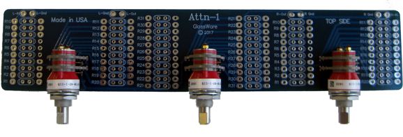
Balanced Step Attenuator The workaround is to build a stepped attenuator, which uses rotary switches and tight-tolerance resistors. (In fact, 0.1% resistors are a good idea.) Alas, 36-position, four deck rotary switches are both ultra-rare and mega-expensive. In contrast, 4-pole 6-position rotary switches, along with 2-pole 12-position rotary switches, are readily available and only expensive, but not mega-expensive (the hard-gold-contact versions are expensive; brass contacts, far, far cheaper). Yes, this is going to be one of my three-knob attenuator designs, for which I am either famous or infamous.
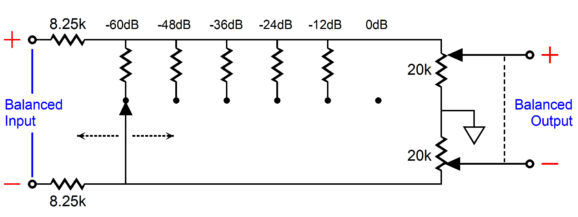
My first thoughts were to resurrect my old B1 Balanced stepped attenuator design, but instead of the original 2-pole 6-position rotary switches use three 2-pole 12-position rotary switches in their place. The B1 Balanced stepped attenuator was hybrid design that used both shunt and series attenuator in cascade:
The two 8.25k input resistors got shunted by both the two 20k series attenuators and a selectable shunting resistor. Each input signal phase sees an identical load, so balance is maintained, no matter to what the output attenuation is set. Here is the actual schematic that shows only one channel.
The center switch controls the output of both channels and offers coarse -12dB steps of attenuation that, then, cascades into the two flanking 2-pole, 6-position rotary switches. These switches give each phase its own series stepped attenuator that terminates into ground. This arrangement creates 36 steps of attenuation in -2dB decrements. It incurs a -3dB insertion loss, however, but this is a small price to pay for such an elegant solution.
Many hate multi-knob attenuators, but I find them essential to be able to make balance-control-like adjustments when listening to old recordings, but not so much with recent recordings. What I didn't like about the design was the -3dB insertion loss and the input impedance dropping to a low of 8.25k, which can prove too low with balanced tube gear.
This graph shows the differential input impedance and the output impedance relative to ground for each phase of output. The workaround I came up with modified the center shunt attenuator that required twice the number of contacts in the center rotary switch.
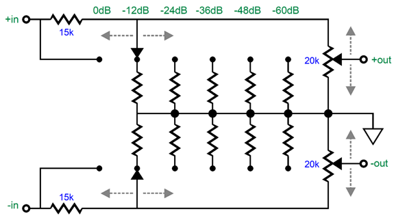
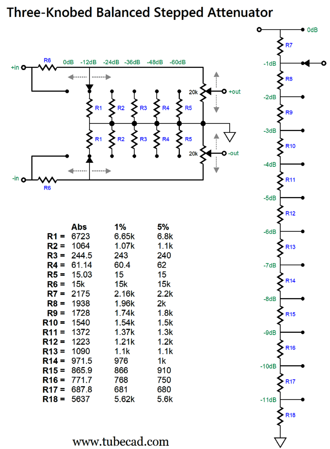
If we use a 4-pole, 6-position rotary switch to provide the coarse -12dB steps for both channels, along with flanking 2-pole, 12-position rotary switches that deliver fine -1dB decrements, we get a total of 72 possible levels of -1dB attenuation, i.e. from 0dB to -71dB. Here is an example that shows just one of the two needed series attenuators needed for each channel.
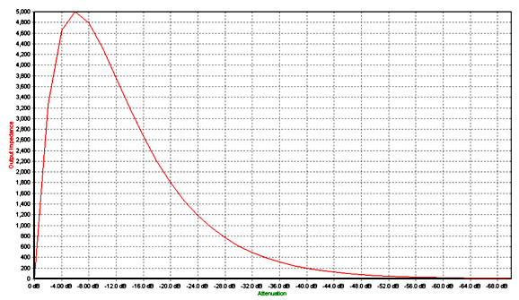
Click on image to see enlargement The input resistors are 15k, which sets limit to the minimum input impedance to 15k, 30k differentially. The maximum input impedance is 20k. The output impedance never exceeds 6.1k, as the following graph shows.
If we used a four-deck 36-position rotary switch with 144 resistors arrayed in a 20k series attenuator configuration, the impedance plot would resemble that of a 20k potentiometer:
The maximum output impedance occurs at -6dB of attenuation, which for a 20k attenuator equals 5k, one fourth of the total resistance in other words.
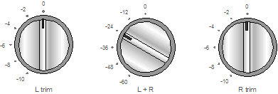
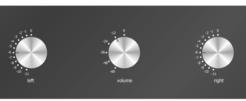
This is what the attenuator would look like on a front panel. With my own ladder attenuator, I have the same layout and decrements. I park the flanking knobs at -6dB, and then bring up the volume with the center knob. If the balance is off or the volume needs tweaking, I then rotate the flanking knobs as needed. The analogy I like to use is that of the coarse and fine focus adjustments on a microscope; start with the coarse, end with the fine.
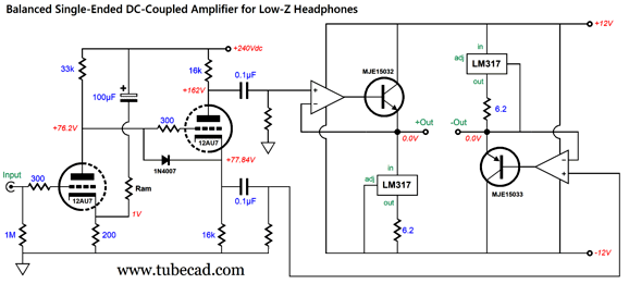
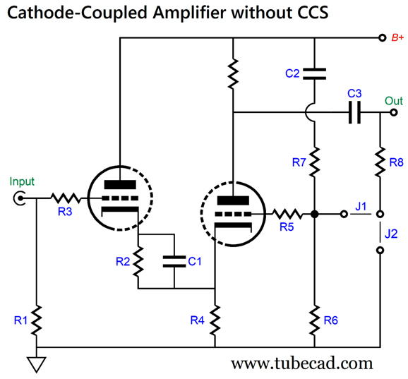
Cathode-Coupled Amplifier without CCS
This is not your father's cathode-coupled amplifier. Indeed, many will fail to recognize it as a cathode-coupled amplifier, since they expect to see something like the following:
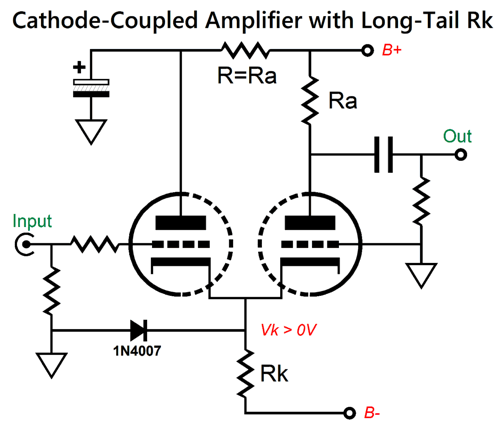
As this classic design stands, it faces two big problems. The first is that since the two triodes cannot share the same cathode-to-plate voltage, but do share the same grid voltage, thus the cathode current flow through the triodes must differ. Is that a problem? It is, if you want less distortion. Ideally, both triodes will see the same cathode-to-plate voltage and cathode current flow. The second problem is that at startup, both cold cathodes are stuck at the negative power-supply rail voltage, while the grids are at ground potential. Not good, as such a huge positive-grid voltage can lead to cathode stripping, wherein chunks of cathode coat rip off due to the extreme electrostatic force, the result of both the high-voltage negative power supply rail voltage and the tiny spacing between the cathode and the grid. The workaround to this second problem is to add a safety diode, one that spans from ground to the cathode. The first problem is usually fixed by adding an RC filter to the input triode's plate. Here is the "fixed" version:
At idle and in use, the cathode voltage will be a few volts positive, so the diode will effectively drop out of the circuit. Okay, let's return to the harmonic-restoration version.
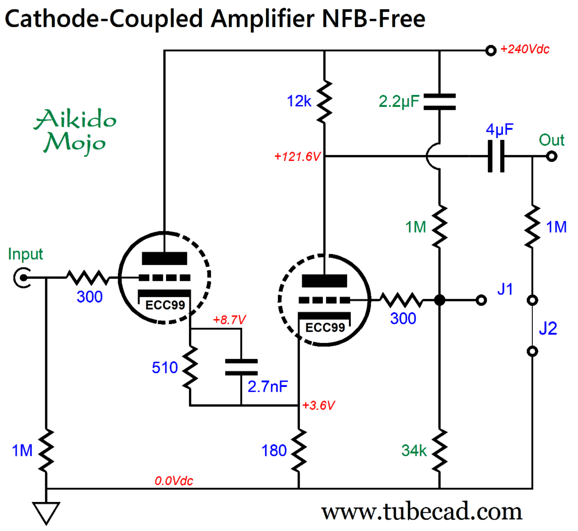
The 1nF capacitor boosts the high-frequency bandwidth, which would otherwise droop off too soon for my taste. This version uses a negative feedback loop, which yields a fixed gain of 6dB, i.e. 1:2. SPICE simulations showed a lovely single-ended cascade of harmonics.
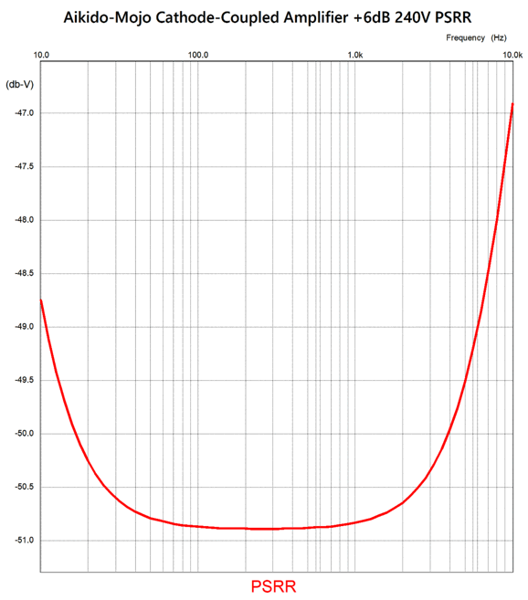
This simulation was with 1Vpk at 1kHz. Oddly, this THD here is lower than I remembered it being. Perhaps, I had originally used a different triode. Since no cathode follower or heavy negative feedback is used, the best choice is in this simple circuit is a low-rp triode. The PSRR proved better than I expected.
Without the Aikido-mojo additions, the PSRR was -11dB. The output impedance was relatively high at 2,500 ohms. Okay, let's now look at a negative feedback-free version.
Note that the 1nF high-frequency boosting capacitor has been replaced by a 2.7nF capacitor. Why? No negative feedback to help extend the high-frequency bandwidth. SPICE simulations pleased me greatly.
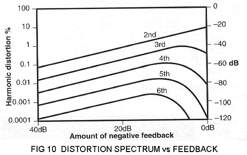
Interestingly enough, the distortion went down, not up. How is that possible? Paradoxically enough, a little amount of negative feedback can make things worse. Peter Baxandall, in his Wireless World, December 1978 article, "Audio Power Amplifier Design," revealed that while 6dB of negative feedback reduces 2nd harmonic distortion, it increased all the higher order harmonics. Back in post 377, I wrote the following:
Let's examine Fig 10, where we see that to get the 5th harmonic back down to the zero negative feedback level would require about 60dB of negative feedback. My adding only 4dB of feedback did lower the output impedance from 4k to 2.5k, but at the cost of worsening the higher harmonics distortion. By the way, both versions of this circuit produced nearly identical PSRR plotlines. I wondered if the cathode-resistor bypass capacitor made a difference in the Fourier plots. It didn't at 1kHz, but might at 10kHz. Here is the frequency response graph for the negative-feedback-free version with and without the bypass capacitor.
With the bypass capacitor, the -3dB high-frequency bandwidth extends about three times further out, 320kHz versus 110kHz. In sum, I quite like this simple design, as it could easily be hard-wired together and 10dB of gain is about optimal for a line-stage amplifier these days. On the other hand, if you are running a power amplifier with low input impedances, say anything below 47k, I would pass on the design. For example, with a 20k load impedance, the bypass capacitor produces a slight peaking (+0.25dB) at 105kHz, which can be quelled by using a 2.4nF capacitor in place of the 2.7nF capacitor. By the way, many of the most acclaimed tube amplifiers of the past produced a seemingly truncated high-frequency bandwidth, let's say only 30kHz. (Transformer ringing above 30kHz isn't going to make things better.)
Music Recommendation: Kaori Muraji's Music Gift to This album contains classical pieces from Bach and Debussy, Beatles songs, and movie music and show tunes, such as "Memory" from Cats. All of it is lovely to hear. I understand that she now has an exclusive contract with the Decca label, and this (along with being marvelously attractive and talented) should make her better known.
Amazon Music beats Qobuz this time, as they offer a 24-bit, 96kHz version of the album, whereas Qobuz delivers a 24-bit, 44.1kHz version.
//JRB
Did you enjoy my post? Do you want to see me make it to post 1,000? If so, think about supporting me at Patreon.
User Guides for GlassWare Software
For those of you who still have old computers running Windows XP (32-bit) or any other Windows 32-bit OS, I have setup the download availability of my old old standards: Tube CAD, SE Amp CAD, and Audio Gadgets. The downloads are at the GlassWare-Yahoo store and the price is only $9.95 for each program. http://glass-ware.stores.yahoo.net/adsoffromgla.html So many have asked that I had to do it. WARNING: THESE THREE PROGRAMS WILL NOT RUN UNDER VISTA 64-Bit or WINDOWS 7, 8, and 10 if the OS is not 32-bit or if it is a 64-bit OS. I do plan on remaking all of these programs into 64-bit versions, but it will be a huge ordeal, as programming requires vast chunks of noise-free time, something very rare with children running about. Ideally, I would love to come out with versions that run on iPads and Android-OS tablets.
|
I know that some readers wish to avoid Patreon, so here is a PayPal button instead. Thanks.
John Broskie
John Gives
Special Thanks to the Special 94 To all my patrons, all 94 of them, thank you all again. I want to especially thank
I am truly stunned and appreciative of their support. In addition I want to thank the following patrons:
All of your support makes a big difference. I would love to arrive at the point where creating my posts was my top priority of the day, not something that I have to steal time from other obligations to do. The more support I get, the higher up these posts move up in deserving attention.
If you have been reading my posts, you know that my lifetime goal is reaching post number one thousand. I have 401 more to go. My second goal was to gather 1,000 patrons. Well, that no longer seems possible to me, so I will shoot for a mighty 100 instead. Thus, I have just 16 patrons to go. Help me get there. Thanks.
Only $12.95 TCJ My-Stock DB
Version 2 Improvements *User definable Download for www.glass-ware.com
|
|||


 to
to 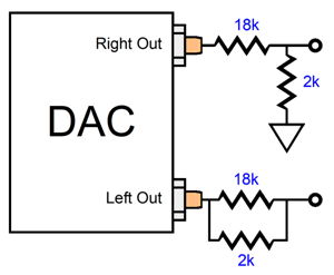


| www.tubecad.com Copyright © 1999-2024 GlassWare All Rights Reserved |