| John Broskie's Guide to Tube Circuit Analysis & Design |
15 June 2024 Post Number 603
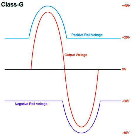
Class-G and Pass Cascode I am old enough to remember when the magazine section of the supermarket held three audio and two electronics magazines: Audio, High Fidelity, Stereo Review, Popular Electronics, and Radio Electronics. (We bought all five, along with Popular Science and Popular Mechanics, and the occasional Scientific America.) Most of my friends' fathers could fix their broken cars, while a few could fix their broken TVs. Can you imagine such a display of virile competence today? In those now defunct magazines, ads for stereo equipment not only often proclaimed new technological innovation, but explicated it. Occasionally, even a schematic was included. Today, ads in audio magazines might boast of new technology, but give it only a trademarked name (such as, Neutron-Diffusion ™, which trust me will have nothing to do with Fick's Law or Boltzmann's equation), but seldom a detailed explanation. The few exceptions, sadly, have often been either misleading or just plain crazy. (For example, I remember reading that the speed of sound leaving a new fancy tweeter design was faster than that leaving a conventional dome tweeter.) Class-G is not a new development, as it is almost 60 years old. Class-G is a modification of the classic class-AB output stage that offers high power output and lower heat generation. The trick lies in the use of a multi-tapped high-voltage power supply to deliver greater power-supply voltage when needed. At idle and at low output, the output-stage output devices connect only to the lower voltage taps, say ± 25Vdc; but as the output voltage swings increases, the output devices smoothly connect to higher power-supply rail voltages. (In class-H, the connection is abrupt.)
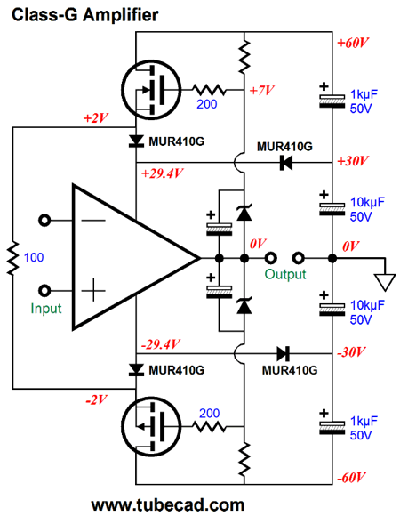
Here only two sets of power-supply rails are used, ± 20Vdc and ± 40Vdc, but third set of ± 60Vdc rails could be added. If the output stage draws a total of 200mA for both channels, then running it off the ± 20Vdc rails will only generate 8W of heat, whereas running of the ± 60Vdc rails would develop 24W of heat. The downside to class-G is added complexity, as commutator diodes and extra output devices and a power transformer with many taps on its secondary and extra rectifiers and power-supply reservoir capacitors must be employed. In addition, many class-G designs include added anti-oscillation circuitry to quell the problem caused by the secondary output devices sharply turning on and off, something I avoid by never letting the higher-voltage devices turn off completely.
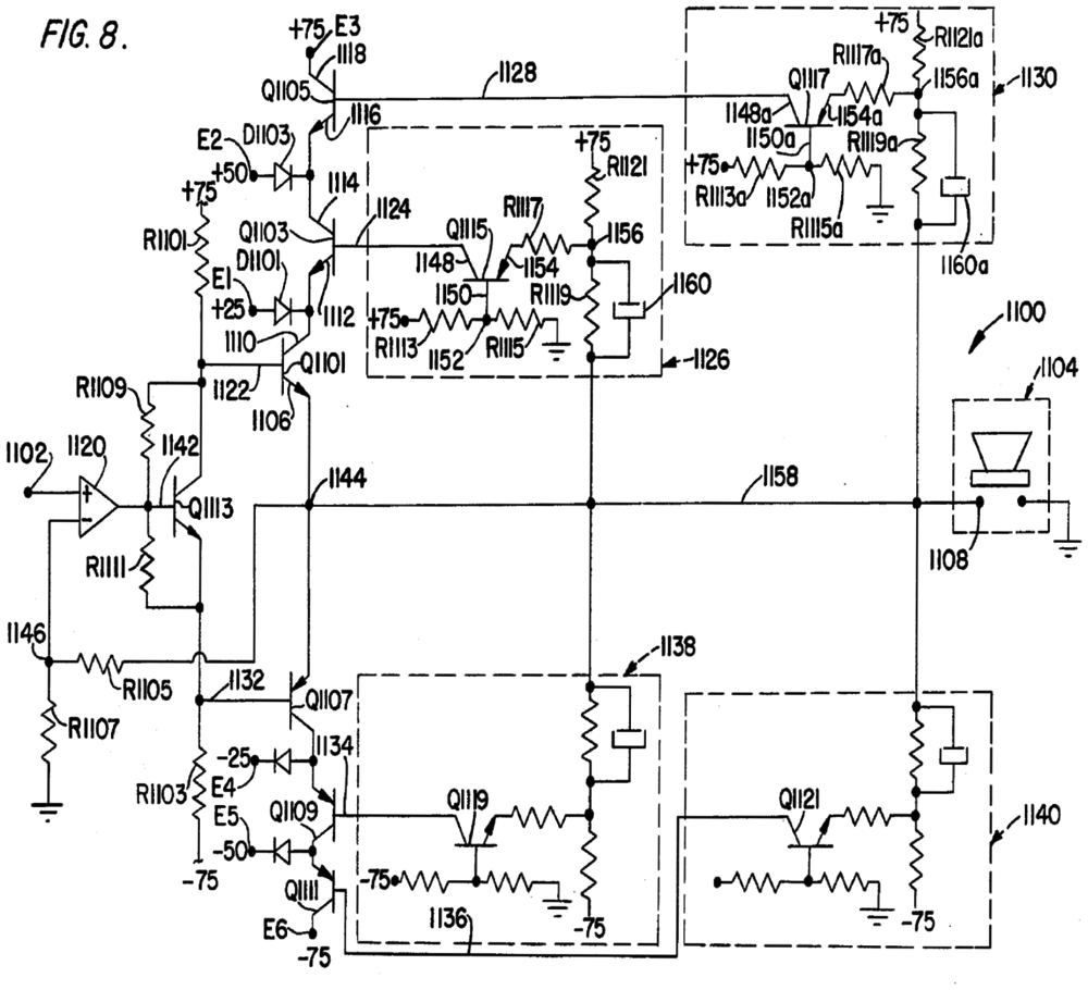
That 100-ohm resistor in the center provides a current path for the MOSFETs. (I would—possibly—use a resistor-capacitor snubber circuit shunting the 100-ohm resistor, say 10 ohms and 0.1µF). As the great American inventor, Thomas Edison (1847 – 1931), pointed out long ago: "The value of an idea lies in the using of it." The one undisputed class-G success had to be Bob Carver's Magnetic-Field power amplifiers: small, light power amplifiers that delivered gobs of wattage. Well, recently I searched out Carver's 1982 patent, US4,484,150, as I remembered him doing Class-G quite differently from other designs. Indeed, he did:
My God, don't you hate patent schematics; I certainly do. Much like the squid's black ink, the point behind the ugly patent drawing is to screen and obscure, to hide what's there. Here is my redrawing of the schematic, but reduced to just a two-stage power supply.
At idle, the output stage works off the ±25Vdc rails. As the output voltage swing approaches the limits of the ±25Vdc rails, the secondary power transistors switch on, allowing the rail voltage to increase up to the new power-supply rail voltage. Since I didn't have any of the parts values, I could only guess at the internal DC voltages. Note that the emitter resistors force a softer turn on of the secondary transistors. This is the feature that I remembered best, as a smoother turn-on might sidestep the switching glitches and oscillations. Interestingly enough, I have never seen this topology used in any Carver repair manuals for his actual products. So why patent it? The patent covers a lot of things other than the class-G output stage. More importantly, class-G has been patented many times, over and over:
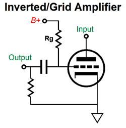
In addition, just about all the major Japanese electronics firms also patented class-G operation. How is that possible? Bad schematics help, but the real reason is closer to the patent system having been broken for a long, long time. Same idea, but different name = new patent. Same idea, but different schematic = new patent. Same idea, but different inventor = new patent. Same idea, but slightly different layout or part types = new patent. Recently, the almost century old inverted/grid amplifier topology was patented.
In spite of it appearing in old electronic textbooks, such as (page 209) in Frederick Emmons Terman's Electronics and Radio Engineering, 1955, McGraw-Hill, the patent office awarded the patent. (I have been told that Telefunken had used the topology in the 1930s.) By the way, I just thought of a possible reason for class-G's failure to launch: US government bureaucracy. The US Federal Trade Commission (FTC) in 1974 issued PART 432—Power Output Claims For Amplifiers Utilized In Home Entertainment Products. This edict killed Dynaco tube-based power amplifiers, as the tube amplifiers could not pass the insane testing requirements. Insane? Indeed, insane. There are applications wherein a power amplifier must deliver full output for hour, such as the powering of a shaker table, where a constant 500W at 10Hz is needed for possibly a few hours. Music differs. Its reproduction usually requires low average power delivery, but with great short-lived dynamic swings in output. (The only exceptions that I can think of are some electronic and some organ music.) In other words, the small, light 400W class-G power amplifier that could work beautifully with the most raucous rock music would fail the FTC tests, as it could not run at full output for an hour without overheating. Class-G amplifiers present an added problem: the switch-on surges of current through the secondary transistors can be severe. For example, let's say the amplifier's output voltage swings 48Vpk and the transistor that connects the output stage to the +75V power-supply rail voltage switches on, thereby passing the 6A peak of current flow; assuming an 8-ohm load, as a 4-ohm load requires 12A peak. Mercy! And as this transistor switches off, its current conduction goes from a low of 6A or 12A instantly down to zero. Mercy, again. Remember that inductance is the property of an electric conductor to oppose a change in current flow. The current flowing through the conductor creates magnetic field surrounding the conductor; a change in current flow develops a counter electromotive force (i.e. voltage). In other words, long wires and any other stray inductance will induce unwanted voltage spikes and glitches. (The commutation rectifiers switching on and off will also lead to or add to this problem. Soft-recovery FRED rectifiers help here.) Returning to Carver's patent, US4484150, here is the entire schematic redrawn:
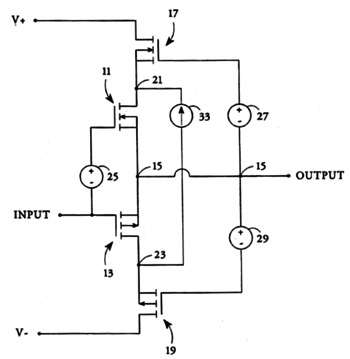
The three sets of rail voltages allow for a huge potential power output, over 300W, yet run a touchable heatsink—a relatively small heatsink. The reason that I searched out the Carver class-G amplifier patent was that Nelson Pass's cascode output stage patent, US Patent, 5,343,166, Efficient High Fidelity Audio Power Amplifier, has been on my mind. Nelson's brilliant idea allows the seemingly paradoxical situation of a power amplifier that idles at a class-A amplifier current flow, but runs cool. The trick is found in using a floating low-voltage power supply to power the output stage devices, while the cascode devices provide a current path to the high-voltage bipolar power supply (and in turn to ground). Unlike the class-G amplifier switching transistors, Pass's cascode transistors never sees severe current-flow disruptions. Since the following patent schematic is so lucidly drawn, we must assume that Nelson himself drew it.
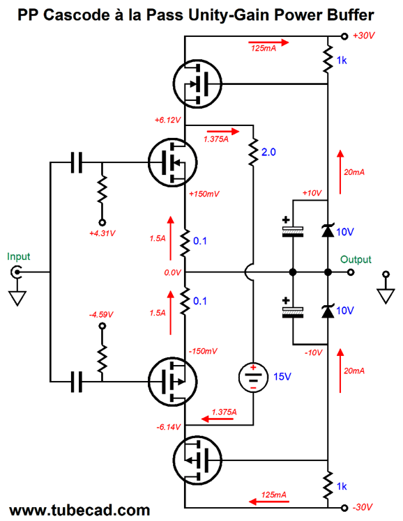
The following is a design example that lets us examine the differing current flows throughout the output stage.
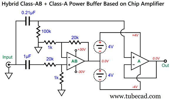
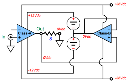
Note that while 1.5A of current flows through the output MOSFETs, the cascode MOSFETs only see 125mA of that current flow, the rest flowing through the floating 15Vdc power supply. The output MOSFETs can deliver 36W of power into an 8-ohm load before exceeding their class-A window of operation, but only dissipate about 18W at idle. (See post 554 for more details.) Without the floating power supply, the idle dissipation would be 90W, which means only 40% efficiency (the theoretical maximum for class-A operation is 50%). The 2-ohm power resistor will get plenty hot, as it sees a 2.75V voltage drop and must dissipate 3.78W. One idea I had was that we could use a floating ±4Vdc bipolar power supply and a solid-state chip amplifier, such as the LM3886, to drive its center-tap. Here is the overview.
Imagine an input signal that peaks at 21V, which after it passes through the two-resistor voltage divider made up from the 20k and 1k resistors after the 1µF input coupling capacitor reduces to 1V peak. Since the gain is equal to (20k + 1k)/1k or 1:21, the peak output from the class-AB is 21Vpk. In other words, unity-gain. What we give up is low distortion, as about 26dB of negative feedback is effectively thrown away. Does this matter? Not as much as you might imagine, as the class-A unity-gain power buffer holds its own negative-feedback loop to clean up its output. Of course, this arrangement radically departs from Pass's patent, being merely a variation on the old (1970s) Super Class-A topology, with the exception that the class-A amplifier does not drive the class-B amplifier's input, as both amplifiers see the same input signal. Here is the Super Class-A topology:
(See posts 449 and 452 for more information on this arrangement.) Actually making an LM3875 or LM3886 work will require more parts.
Note the absence of an input coupling capacitor and of the capacitor that normally terminates the negative feedback loop's 1k resistor. In other words, this is a DC-coupled power buffer, which will pass along any DC offset voltage at its input. Is this a big problem? No. The class-A unity-gain power buffer is responsible for eliminating any DC offset, so it little matters if its bipolar power supply voltages do not center at ground potential. What we need now is the class-A unity-gain power buffer. One idea that comes to mind is the compound arrangement.
Quote from post 459:
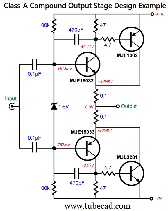
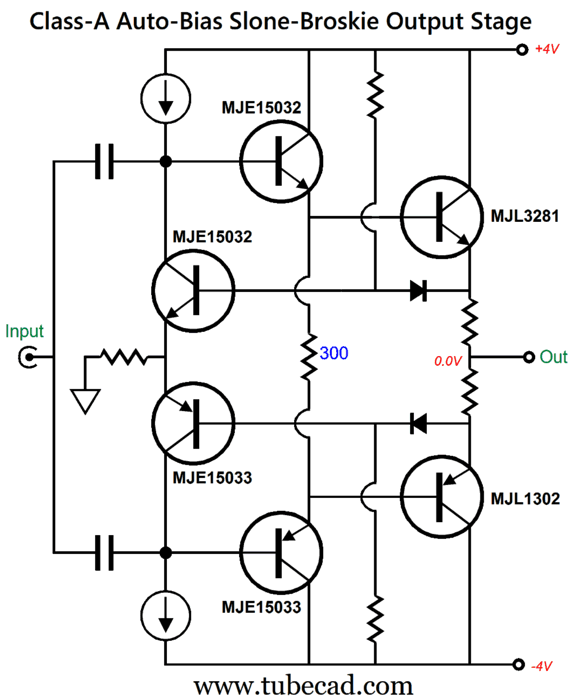
Here is a simple class-A unity-gain power buffer:
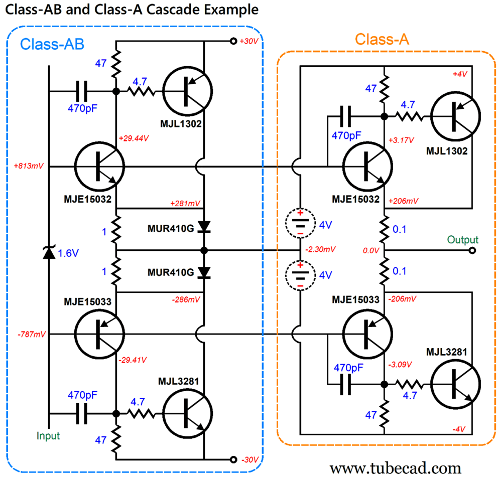
Note the wee ±4Vdc bipolar power supply rail voltages. The compound arrangement makes for greater linearity in a class-A output stage, but not necessarily in a class-AB output stage, as gm-doubling problem is worsened by its sharper cutoff. On the other hand, gm-doubling is a feature of class-A output stages, not a bug. In fact a class-A push-pull output stage relies on gm-doubling to bring the class-A magic. In this compound circuit, the input transistors (MJE15032 & MJE15033) control the output transistors (MJL1302 & MJL3281). In other words, negative feedback; 100% negative feedback. Well, what if we cascade (i.e. place in series) two push-pull compound circuits, one class-AB and one class-A, the class-AB driving the floating power supply, while the class-A drives the loudspeaker.
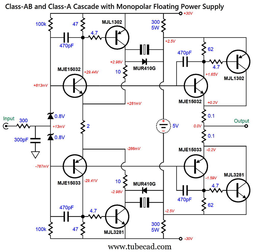
Note that the same transistors are used in both compound-based buffers. Also note that the emitter resistor values differ, which results in the differing idle currents, 281mA and 2.06A. The two MUR410G rectifiers are there to limit the maximum voltage drop across the 1-ohm emitter resistors to no more than about 0.6V; without the rectifier, the voltage drop could exceed 4Vpk, which would subtract from the otherwise potential output voltage swing. The 470pF capacitors prevent high-frequency peaking. The question I asked myself was: Could we use this compound cascade arrangement with a floating monopolar power supply? My first conclusion was, no. An answer not to my liking. I then remembered Pass's cascode patent. It took some head scratching, but I came up with a yes-worthy and patentable solution.
At idle, the two compound stages only couple through the non-polarized electrolytic capacitors, as the rectifiers are not forward biased. The class-A compound power buffer connects to a path to ground via the two 300-ohmm resistors and the connections to the bipolar power supply. The two 10-ohm and one 2-ohm resistors establish the class-AB compound buffer's two DC offsets (+2.98Vdc and -2.98Vdc). As the output voltage swings away from ground potential, the rectifiers engage and pull the floating power supply up and down as needed, as the rectifiers become forward biased. The next puzzle I faced was how to use a single-ended rather than push-pull class-A output buffer. Here is my solution.
I decided to try using the bastode differential amplifier in place of the simpler compound. I had to double up on output transistors and on the idle current flow (now 4.4A), as the maximum output current swing of a single-ended output stage is equal to its idle current flow. The 1N5401 rectifier is merely a voltage displacer. The 1.1V zener (or voltage reference) transform the bottom NPN transistors into constant-current sources, with each idling at 2.2A. The advantage that the bastode arrangement holds over the simpler compound arrangement is that we get a "free" current path for the zener and we can tweak the bastode by adding an emitter resistor between the two emitters. The problem common to both arrangements is that unity-gain derived from 100% negative feedback can get tricky fast. In contrast, here is another possible class-A push-pull power buffer design:
The two diodes act as voltage displacers, which allow the use of smaller-valued emitter resistors. The leftmost transistors auto-bias the output transistors, while the center transistors drive the output transistors on the right. We can get simpler, by using a single bias transistor:
Note the ±5Vdc rail voltages. The MJE15033 PNP transistor monitors the voltage drop across the two 0.1-ohm emitter resistors. The reason we can get away with such a low emitter-to-base voltage on this transistor is that it only draws 0.25mA.
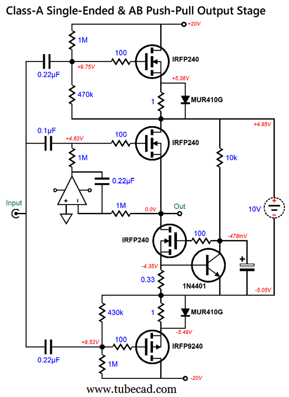
To complete the Pass-cascode design is easy enough:
The OpAmp forms a DC servo circuit that eliminates a DC offset from appearing at the output. The top and bottom MOSFETs idle at 400mA, while the two center MOSFETs idle at 2.1A. Well, this circuit worked fairly well in SPICE simulations, but I noted some small bumps below 10Hz. The workaround was to replace the MJE15033 transistor with another OpAmp.
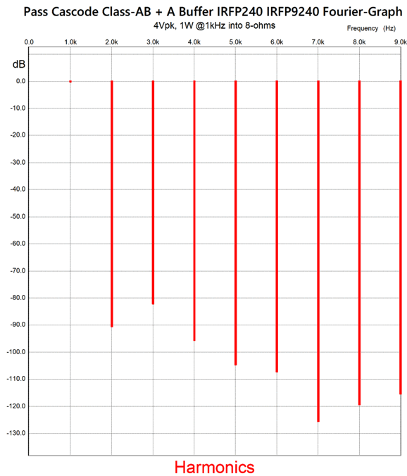
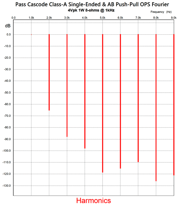
The top OpAmp sets the idle current for both center MOSFETs; the bottom OpAmp centers the output, thereby eliminating a DC offset. Note that only the top MOSFET gets a source resistor. Why? To equalize the transconductances between the N-channel MOSFET and P-channel MOSFET. The SPICE simulations revealed a lovey single-ended-like array of harmonics. We start with one watt of output at 1Khz into an 8-ohm load.
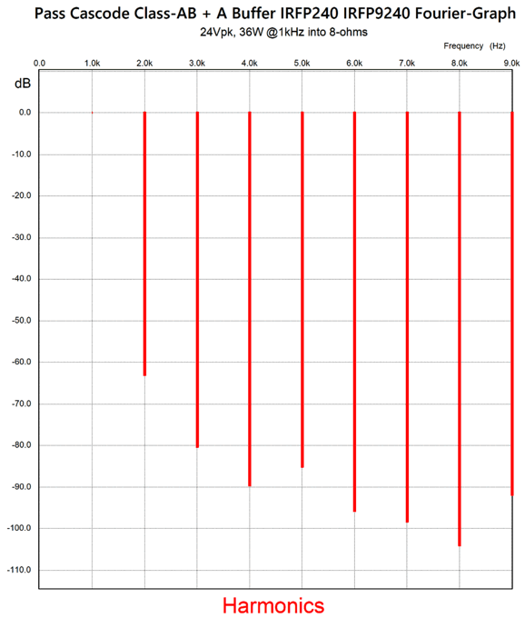
The unspoken assumption here is that this unity-gain power buffer would be driven by a tube-based signal amplifier, which means that we can expect some added 2nd harmonic distortion. At full output, 36W, we still see a fine set of harmonics.
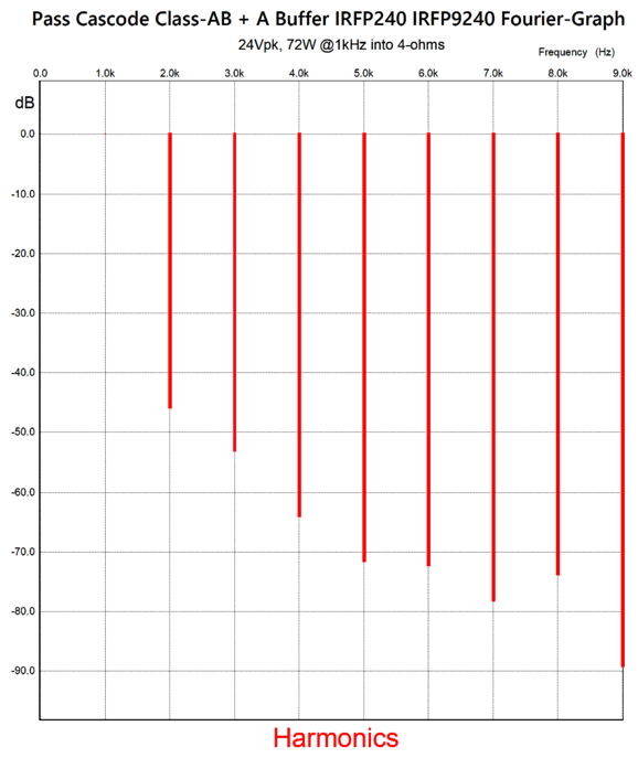
Note that the 3rd harmonic almost remains unchanged, with it being down -80dB at both output levels. Bear in mind that being down -80dB equal 0.01% distortion. In other words, in spite of no negative feedback loop, relying entirely on a high idle current and degenerative feedback, this buffer performs exceedingly well. The hard test is with a 4-ohm load.
Yes, the distortion increased, but the single-ended cascade of harmonics remains. Note that extra-fine 5th, 7th, and 9th harmonics. Since single-ended is the ideal, why not go single-ended? Single-ended with an inductive load (either a choke or an output transformer) achieves a theoretical maximum efficiency of 50%, the same as the class-A push-pull output stage. Single-ended loaded by a constant-current source only achieves a theoretical maximum efficiency of 25%. Well, that's with the typical arrangement, not with the Pass cascode. For example, say we desire a peak power output of 16W into an 8-ohm loudspeaker, then we will need an idle current of at least 2A and bipolar power supply rail voltages of around ±20Vdc. So far, we are looking at 80W of heat dissipation at idle.
In contrast, if you employ the Pass cascode arrangement, the floating power supply can be only 10V, which against the 2A of idle current flow equals only 20W of dissipation. Next, we use a bipolar power supply rail voltages of ±20Vdc and let the cascode MOSFETs idle at 400mA. Since these cascode MOSFETs see a source-to-drain voltage of 15 volts, they must each dissipate 6W at idle. What will be their peak dissipation? A super interesting question. We start by realizing that they effectively work under a ±15Vdc bipolar power supply, not a ±20Vdc one. Next, the must lower the load resistance from 8 ohms to 5.3 ohms in our calculations, as that load impedance will force the same peak current flow at full output (nominally 16W into 8-ohm loads). Throwing these changes in the formulas delivers 12W as the cascode MOSFETs' maximum dissipation. This assumes an 8-ohm load. Normally, when doing these calculations it is a good idea to be super pessimistic. In other words, it's a good idea to double the expected dissipation, i.e. to 24W, as 4-ohm loudspeakers are common and many nominally 8-ohm loudspeaker dip much lower at certain frequencies. The single-ended center buffer, however, imposes a 2A current limit with negative swinging output voltages, but not a limit on positive voltage swings. Okay, what is the peak maximum output stage dissipation? I would split the difference, i.e. 18W. Next, we need to add the 20W of dissipation from the single-ended center buffer, making a total of 38W. Why is this important? Heatsinks. We need to calculate the needed thermal resistance of the heatsink. I like to impose a maximum heatsink temperature of 60 ° (Centigrade), along with observing the output devices' maximum junction temperature (usually, 125C or 150C). Here are the assumptions: TO-247 MOSFETs present a thermal resistance of 0.83C/W; insulator thermal resistance, 1C/W (can be lower); heatsink thermal resistance, 0.6C/W; and an ambient temperature of 35C (95 °F). The heatsink temperature would be 57.8C; the junction, 75.2C. Mind you, a heatsink thermal resistance of 0.6C/W implies a fairly big and heavy heatsink. Moreover, this is for just one channel. We could make the floating power supply the conventional way, using a power transformer and bridge rectifier along with a big capacitor—or we could use a switch-mode power supply, which are both cheap and small. In fact, we could use a boat battery. Why boat? Deep-cycle batteries differ from cranking batteries. In a boat or in a camper, we need long steady power for microwaves, TVs, stereos, lights; for this use a deep-cycle is best. In contrast, in our cars, trucks, even boats, we need a huge current delivery of 100A to 400A to crank the engine; for this use a cranking battery is best. Apparently they make special batteries that straddle both current deliveries. All batteries are expensive, but deep-cycle batteries are especially expensive. (A high-end deep-cycle battery can easily cost $400.) The $20 150W 12V switcher in a closed frame looks much better now. Bear in mind that we risk EMI and audio noise and high-frequency ripple from switching power supplies. How well does this variation with the center single-ended buffer work in SPICE simulations? Here is the Fourier graph for 1W of output into 8-ohm load and at 1kHz.
Not as good as I would have expected. In fact, I prefer the harmonic structure from the class-A push-pull version of the center power buffer.
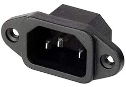
Rectangular Metal Punch
Extremely well made, this punch works beautifully. With this roadblock removed, my mind fills with new possible tube-based projects.
Music Recommendation: 24-Bit, 192kHz
First classical albums, then jazz:
Gesualdo Six, Byrd Mass for Five Voices; Ave verum corpus; Lamentations & Other Works
Gesualdo Six, Christmas
Gesualdo Six, Fading
Gesualdo Six, Morning Star Music for Epiphany Down the Ages
Tenebrae Responsories for Maundy Thursday; Tallis Lamentations
Piano Trios of Weinberg, Auerbach, & Dvořák
Marais, Marin Folies d'Espagne, La Reveuse
Dutilleux, Henri Tout un monde lointain - Symphony No. 1 - Métaboles
Byrd, William The Golden Renaissance
Art Blakey and The Jazz Messengers Caravan
Kenny Burrell Midnight Blue
Duke Ellington Concert In The Virgin Islands
//JRB
Did you enjoy my post? Do you want to see me make it to post 1,000? If so, think about supporting me at Patreon.
User Guides for GlassWare Software
For those of you who still have old computers running Windows XP (32-bit) or any other Windows 32-bit OS, I have setup the download availability of my old old standards: Tube CAD, SE Amp CAD, and Audio Gadgets. The downloads are at the GlassWare-Yahoo store and the price is only $9.95 for each program. http://glass-ware.stores.yahoo.net/adsoffromgla.html So many have asked that I had to do it. WARNING: THESE THREE PROGRAMS WILL NOT RUN UNDER VISTA 64-Bit or WINDOWS 7, 8, and 10 if the OS is not 32-bit or if it is a 64-bit OS. I do plan on remaking all of these programs into 64-bit versions, but it will be a huge ordeal, as programming requires vast chunks of noise-free time, something very rare with children running about. Ideally, I would love to come out with versions that run on iPads and Android-OS tablets.
|
I know that some readers wish to avoid Patreon, so here is a PayPal button instead. Thanks.
John Broskie
John Gives
Special Thanks to the Special 85 To all my patrons, all 85 of them, thank you all again. I want to especially thank
I am truly stunned and appreciative of their support. In addition I want to thank the following patrons:
All of your support makes a big difference. I would love to arrive at the point where creating my posts was my top priority of the day, not something that I have to steal time from other obligations to do. The more support I get, the higher up these posts move up in deserving attention.
If you have been reading my posts, you know that my lifetime goal is reaching post number one thousand. I have 397 more to go. My second goal was to gather 1,000 patrons. Well, that no longer seems possible to me, so I will shoot for a mighty 100 instead. Thus, I have just 15 patrons to go. Help me get there. Thanks.
Only $12.95 TCJ My-Stock DB
Version 2 Improvements *User definable Download for www.glass-ware.com
|
|||


| www.tubecad.com Copyright © 1999-2024 GlassWare All Rights Reserved |