| John Broskie's Guide to Tube Circuit Analysis & Design |
30 Junel 2024 Post Number 604
Radical Electrostatic Headphones
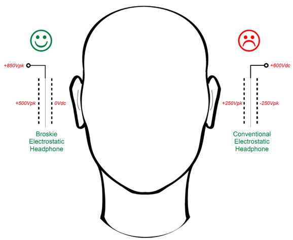
Excerpted from American Heritage Talking Dictionary Last year in post 579, I argued for a radical departure from existing electrostatic driver practice. Yes, radical. First, no push-pull, only single-ended. Second, one fixed, i.e. grounded stator and a half-driven diaphragm and a fully driven stator. Single-ended is, as far as my ears are concerned, a goal and a good in itself, as its harmonic structure mimics physical existence—even air exhibits a single-ended signature. The argument for the one-fixed stator arrangement, at least for headphone use, is that it is safer, as it places a ground-potential shield between your ear and the high-voltages.
Ears sweat; headphones both make ears sweat and trap the sweat; high voltages, moisture, and flesh create an inherently dangerous situation. This explains why electrostatic headphones go to such great lengths to keep your ears isolated from the nearby stator. In contrast, electromagnetic planar headphones get away with a single thin layer of cloth or plastic screen to filter away dust. If the stators next to the ears were grounded, no high-voltage danger exists, thereby allowing us to use the same thin layer of cloth, not the elaborate and thick insulation foam and plastic mesh and cloth used. Is it possible for an electrostatic driver to work with a grounded stator? Yes. The key item to scrutinize is the diaphragm's voltage relationships to the two stators.
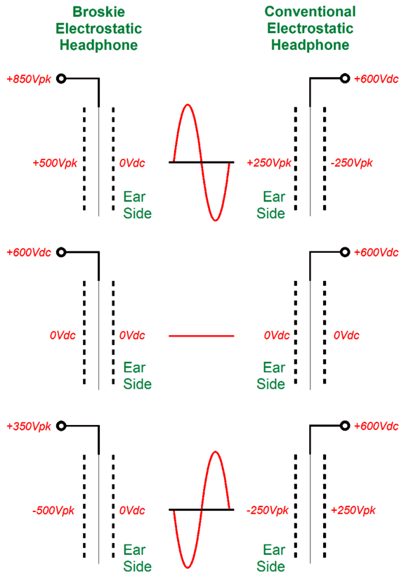
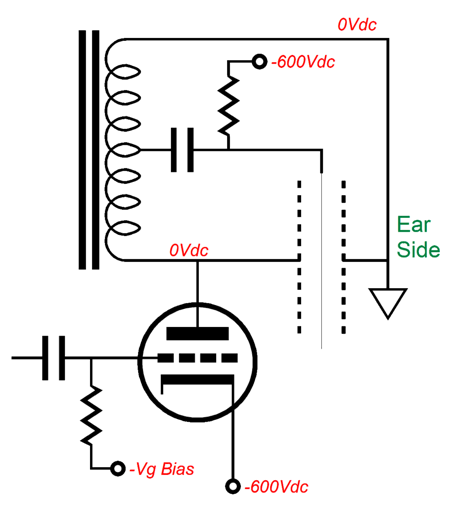
As far as the diaphragm is concerned, NOTHING has changed. Do the math yourself, as no more than addition and subtraction is needed. Obviously, at idle, the two arrangements present the exact same diaphragm-to-stators voltages, as the stators are at ground potential. Well, the same holds true for huge voltage swings, both positive and negative. Bear in mind, grounding one stator does not require single-ended amplification. The following schematic shows a transformer-coupled electrostatic headphone amplifier that conforms to the Broskie grounded-stator arrangement.
The amplifier can be either a push-pull or single-ended design. (The amplifier will have to deliver both voltage and current. The higher the transformer winding ratio, the more current will be needed. How much power? My quick guess: about 2W.) We can use a center-tapped inductor and single-ended triode output stage to conform to the Broskie arrangement.
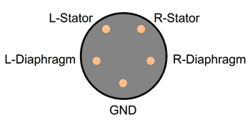
An air-gapped inductor core will be needed, and the center-tap must fall at 50%. Note the negative bias voltage on the diaphragm, which is something rarely if ever employed—yet should be. Why? Most airborne dust particles are negatively charged, which explains why cheaper electrostatic-dust collectors just use a positively charged dust collector. (If the dust can float in the air, it must be made of lighter elements, which offer a tighter hold on their electrons, unlike heavy elements, such as copper, gold, silver, iron, lead, that present less of a grip.) If you are old enough, you might remember how TVs and computer monitors that used a cathode-ray tube (CRT) always collected a coating of dust. This was due the cathode emitting electrons that hit the positively charged screen, which also attracted negatively charged dust particles on its outside surface. By the way, in order for solar cells to deliver their potential juice, they must be clean, dust and dirt free, which requires lots of water (very clean water at that) and energy (dry cleaning scratches the surface, thereby decreasing the electrical yield). The new alternative is to pass a high-voltage charged (-12kV) plate over their surfaces. Why a negatively charged plate? Sand, which is common at solar farms, tends to be charged positively (it depends on the sand's size). Returning to electrostatic headphones, the biggest hurdle that my alternative arrangement faces is that the headphone plugs would not be backwards compatible, as the fifth pin would no longer attach to both diaphragms, but to the grounded stators. In other words, the five-pin plugs and jacks could still be used, but they must be differently wired. (Each electrostatic headphone driver would still get three wires.)
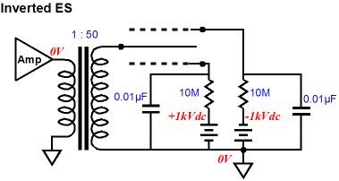
In addition, the diaphragms should have a low-resistance coating, not a high-resistance one. Metal coated and anti-static plastic films are readily available, but probably are too thick. I have heard at audio shows inverted-electrostatic loudspeakers, wherein the stators are fixed with high-voltage bipolar voltages, and the diaphragm is at ground potential and is the driven element. They sounded great.
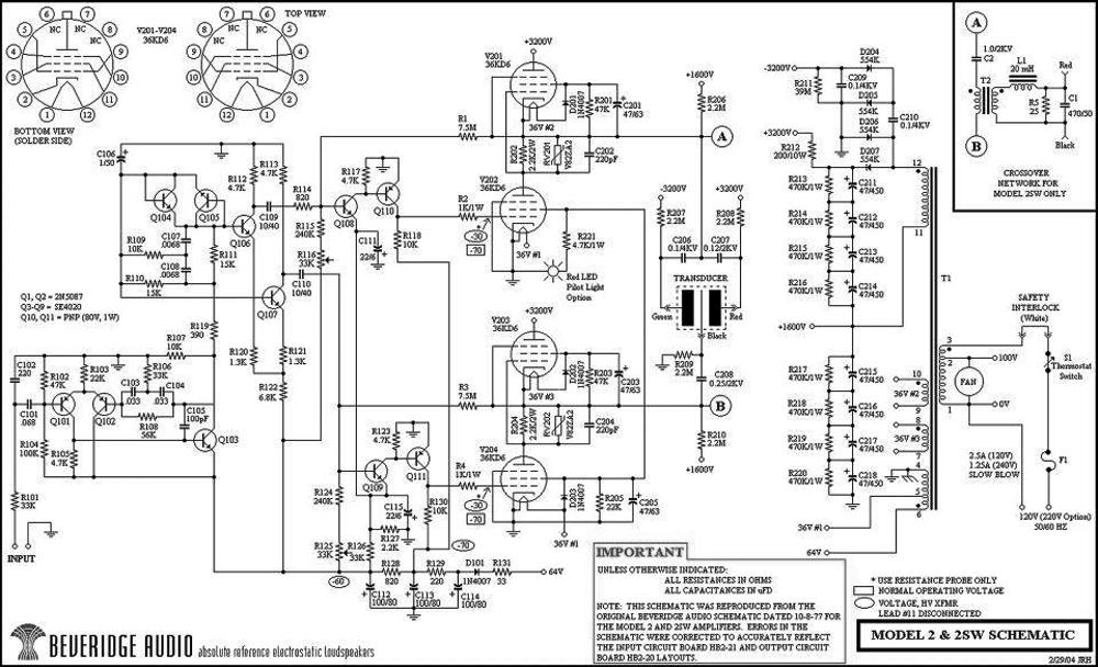
In the Beveridge electrostatic loudspeaker, both the diaphragm and the stators were driven.
Each loudspeaker holds two high-voltage SRPP stages that operate in anti-phase. The top SRPP drives the two stators, while the bottom SRPP drives the diaphragm. Okay, since I believe that I have established that this "radical" arrangement for electrostatic headphones (also applies to electrostatic loudspeaker) can work and will prove safer, we can move on designing a single-ended amplifier to drive electrostatic headphones. We will start with those designs that use a fixed, i.e. grounded high-voltage power supply.
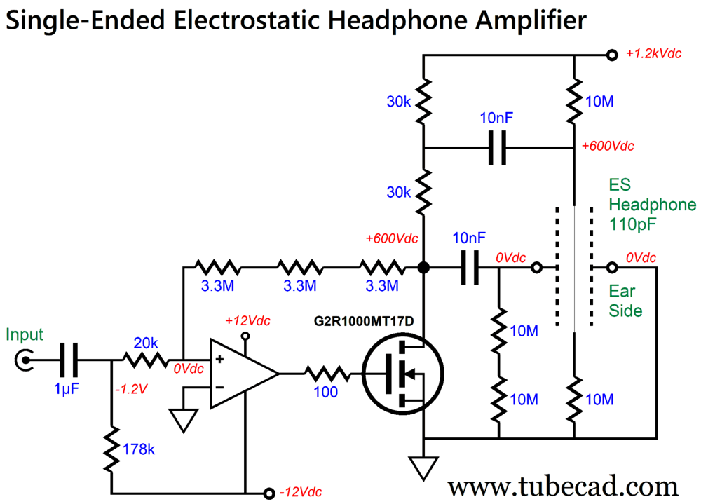
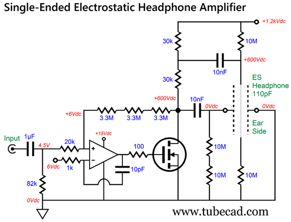
Fixed-Power-Supply Designs In the previous section, we saw how a center-tapped inductor and single-ended triode were used in the Broskie electrostatic arrangement with a grounded stator. The center-tapped inductor halves the output signal, which is precisely what the diaphragm needs to see. Well, a two-resistor voltage divider can do the same. In the following design, we see two drain resistors in series.
The OpAmp and SiC MOSFET combine to create an inverting amplifier topology. The gain is set by the ratio between the 20k input resistor and the 9.9M negative feedback resistor(s), which equals 1 : 495 (+54dB). In other words, 1Vpk of input signal will prompt 495Vpk of output signal, with the two 30k resistors yielding 247.5Vpk for the diaphragm. The diaphragm is biased to +600Vdc at idle. The 178k resistor that terminates into the -12Vdc power-supply rail forces the 600Vdc drain voltage, as that is the voltage that delivers 0Vdc to the op's non-inverting input. Depending on the OpAmp used, the following addition might be required to ensure high-frequency stability.
By the way, if the two-resistor voltage divider aspect of the two 30k drain resistors bothers you conceptually, compare it to the following circuit, which effectively loads the MOSFET in the exact same way.
The two 220pF capacitors present 110pF of capacitance, while the two 30k resistor add up to a 60k resistive load. Due to the 20k input resistor, the input coupling capacitor must be relatively large in value (1µF) to ensure low-frequency response below 20Hz. Well, since we must employ an input coupling capacitor, do we really need to use a bipolar power supply for the OpAmp? No, as the following design shows.
I should mention why so many of the resistors are in series with other resistors. All resistors are specified for a maximum voltage differential. The longer the resistor body, usually the higher the maximum voltage. Many 1W resistors specify a 350V voltage differential. (This has nothing to do with its power dissipation limit, but with its ability to avoid internal arcing. For example, a 1W, 1M resistor seems to imply a maximum voltage of 1kVdc, while 1W, 1-ohm resistor implies a 1Vdc maximum.) In addition, resistors exhibit a voltage-induced distortion, and electrostatic amplifiers hold a lot of voltage. In other words, I was probably too stingy in the drawing of these schematics, as many more resistors should have been shown in series. For example, in the schematic above, the 30k drain resistors might be made up from three 10k 2W resistors in series. No doubt some are wondering why we cannot replace the SiC MOSFET with a triode. We can, but we must add a PNP transistor and high-voltage negative power-supply rail, if we are going to use the typical audio-grade OpAmp.
Note the OpAmp's return to conventional arrangement, as the added transistor inverts the OpAmp's output. The only triodes that come to mind that would work well in this circuit are the 6BL7, 6BX7, and SV572-30. The 600V plate voltage and the 6W of dissipation limit our choices. No doubt some suitable pentodes exist, but then we have to deal with the grid-2 voltage. Moreover, the pentode's much higher gain will make negative feedback stability much more of an issue. One possibility, however, might be to use a triode-connected EL34.
This EL34 is triode-connected in AC terms by the 1µF capacitor that bridges the plate to the screen (G2). The 91k resistor provides the needed 100V voltage drop. Why is a 100V voltage drop needed? The following is from the Mullard datasheet for the EL34:
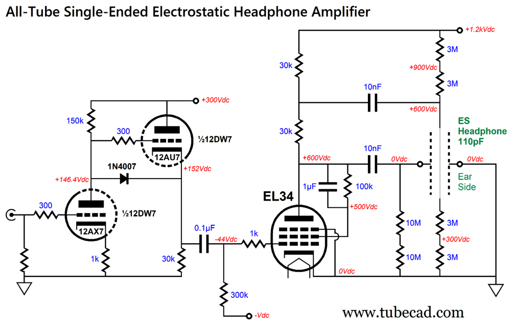
Bear in mind that the EL34s made in 1962 by Mullard are NOT the same EL34s made in China today—nor were the EL34s made by Mullard the equal of those made by Telefunken (with the metal bases). Thus, I want to play it conservative and take the 500V grid-2 maximum as being the design limit. By the way, note how the triode-connected dissipation limit drops from 30W at a static plate voltage of 500V to 15W with a 600V plate voltage. Of course, we could go all-tube and zero negative feedback.
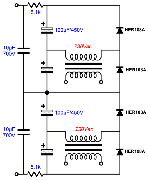
The 12DW7 is twin-triode that hold dissimilar triodes; in this tube, 12AX7 and 12AU7 triodes. In this amplifier, we see the 12AX7 triode providing gobs of gain, while the 12AU7 triode functions in the cathode follower configuration. The final gain is 1 : 460; in other words, with 1Vpk of input signal, we see 460Vpk of voltage swing at the plate of the EL34. In SPICE simulations, the THD was below 1% at 460Vpk at 1kHz. The high-frequency bandwidth extends out to 400kHz. Not bad considering that no negative feedback loop is used. Making the power supply for this circuit gets tough due to the high voltages. We could use two 30VA 230Vac power transformers to create the power supply, while using relatively low-voltage capacitors and rectifiers.
Two voltage-doubler rectifier circuits are stacked. The four 100µF/400V electrolytic capacitors might seem to be excessively overrated in terms of voltage. The more I look at the circuit, the more inclined I am to use four 450V electrolytic capacitors instead. Why? When it comes to high-voltage, seldom can we be too conservative—or paranoid. Let's return to all-solid-state designs. Why? One reason is that it is more difficult, compared to all-tube designs, which makes it more interesting. Moreover, the decisive feature that solid-state offers over tube-based circuits is low noise. We are happy to live with noisy power amplifiers driving loudspeakers, but the same amount of noise would prove intolerable when delivered to headphones. I went through my old notes looking for designs. I found the following:
In spite of there being so much to like, such as the non-inverting configuration of the OpAmp, the input RC low-pass filter, the negative polarizing bias voltage for the diaphragm, and the DC coupling throughout, the design still earns the uncommitted face icon. Why? I don't much like the many-transistor cascoding. Here is a radical idea: use an optically-coupled (or WiFi-coupled) DAC to drive the high-voltage SiC MOSFET.
The OpAmp and the DAC run off a floating 12V power supply that terminates into the -1.2kVdc power-supply rail. Note that the OpAmp only directly controls the signal at the MOSFET's source. This makes this a current-output amplifier, one that terminates into a 60k resistance shunted by 110pF of capacitance, which in turn defines a 1st-order low-pass filter at 24kHz. In other words, this filtering must be included in the DAC's scheme of post filtering. (We could extend the high-frequency bandwidth by shunting the 100-ohm source resistor with a small-valued capacitor.) I quite like the idea of controlling the electrostatic headphone amplifier's output via a phone app, as I could also stream music and apply balance corrections and equalization.
Floating-Power-Supply ES Designs
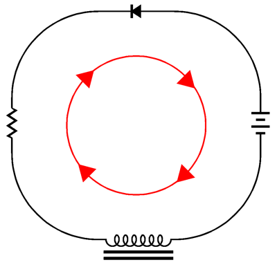
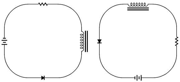
We can move any part round and over other parts as long as we retain the orientation that allows current to flow.
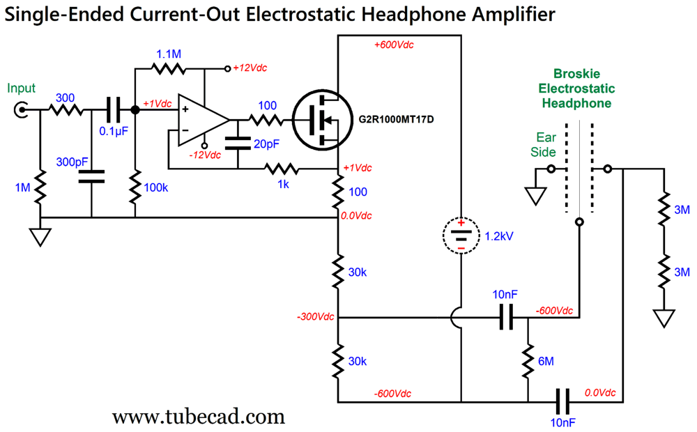
Both these rearrangements sustain the exact same current flow. The next step is to apply this principle to the design of a single-ended electrostatic headphone amplifier. The reader needs to review the previous design before moving on to new designs. Indeed, it wouldn't hurt to reread post 572, as it explicates the rearrangement of parts within the circle of current conduction. In the previous design, we saw a fixed negative power-supply rail voltage of -1200Vdc, the SiC MOSFET's source separated from the -1200V by a 100-ohm resistor. Well, we can un-ground the high-voltage power supply and pull up the source resistor and the MOSFET to ground potential, and then spin the two 30k drain resistors around until the string terminates into ground.
This unusual output stage functions identically to the previous design, dissipating the same amount of heat, producing the same amount of distortion, realizing the same high-frequency bandwidth—and the same PSRR. How's that possible? A current-output amplifier presents a supremely high output impedance (by design), which was a feature in the previous design and in this one. Both the fixed and floating power supplies exhibit ripple and rectifier noise, but none of the power-supply noise appears at the end of the drain resistor string. Nonetheless, we should always strive to deliver clean voltage to any audio circuit. Here is a floating high-voltage power supply (each channel requires one).
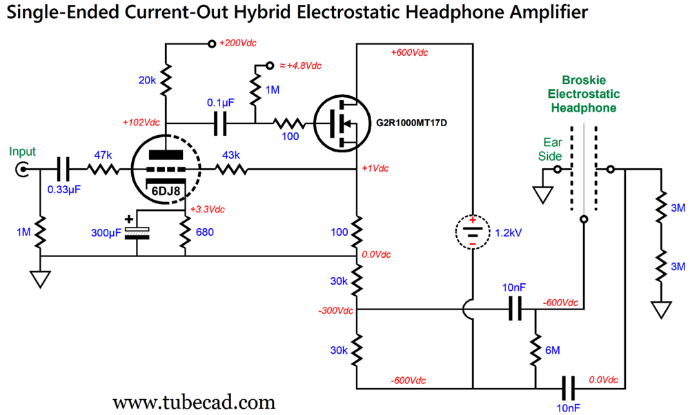
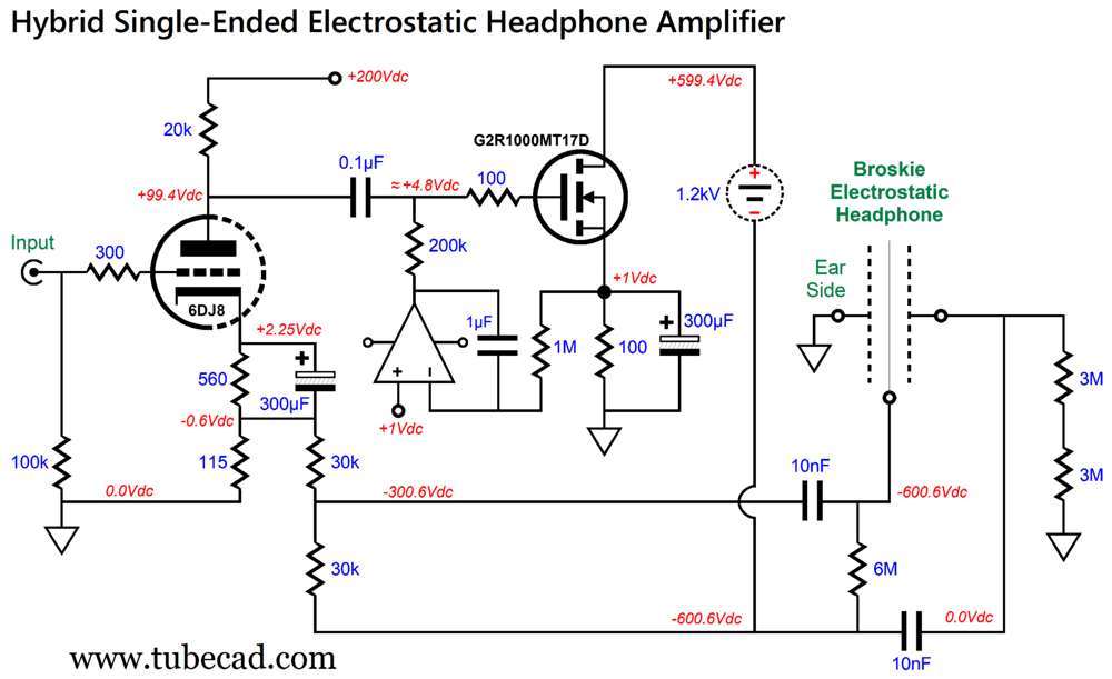
Returning to the circuit, note that the OpAmp strives to duplicate its input signal upon the 100-ohm source resistor. Thus, whatever current-flow variation resulting will also be imposed upon the 60k load resistance. An input signal of 1Vpk will induce 1V/100-ohms of peak current variation, making for 600Vpk voltage swings. In other words, the gain is equal to 1:600. To reduce the gain to 1:500, we replace the 100-ohm resistor with a 120-ohm resistor and increase the OpAmp's reference voltage to 1.2Vdc. Once again, as this is current-output amplifier, the 60k resistance shunted by 110pF of capacitance defines a 1st-order low-pass filter at 24kHz. We can replace the OpAmp with a triode.
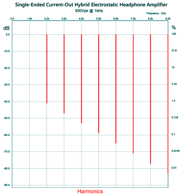
The 6DJ8 is configured as an anode-follower with the MOSFET acting as source-follower. The cathode resistor must be sufficiently larger in value absorb the +1V bias voltage on the grid. How well does this circuit work? In SPICE simulations the THD was about 1% at 500Vpk at 1kHz. The harmonic structure painted a lovely picture of the single-ended cascade.
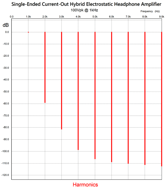
(Note the percentages at the right side of the graph.) How much better did the OpAmp-based version perform? Not much, as all the harmonics were down a further -10dB. I expected much more. What I believe is going on is that the Fourier analyses is being tricked up by phase shift, which it confuses with harmonic distortion. By the way, most electrostatic headphone amplifiers have their distortion specified at only 100Vpk, not 500Vpk. Here is the Fourier graph for 100Vpk with this hybrid circuit.
Almost 0.1% THD, which is amazing when you consider how simple the circuit is and how little negative feedback is employed. Indeed, my mind travels off to cathode follower power amplifiers, a single-ended amplifier at that. Imagine a 300B with the output transformer loading its cathode, not its plate. Now imagine we reduce the floating power supply voltage to 500Vdc. This electrostatic headphone amplifier now becomes a frontend to drive the cathode follower output stage, which would deliver low distortion and output impedance. Hell, we could also replace the SiC MOSFET with a 12B4 triode. We can extend a negative feedback loop to the output, thereby reducing the output impedance and increase the high-frequency bandwidth.
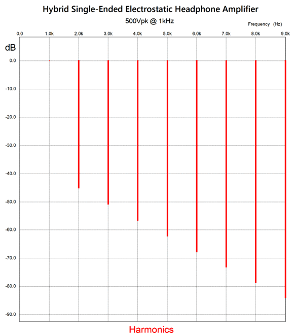
The MOSFET's 60k of load resistance becomes the negative feedback loop that terminates into the 115-ohm cathode resistor. Note the negative voltage at the cathode resistor. The DC servo auto-biases the MOSFET idle current. With the decrease in output impedance, we get an increase in high-frequency bandwidth; in this example, up to 110kHz. I expected to see a reduction in distortion, if for no other reason that the extended bandwidth having reduced phase shift at 1kHz.
Note the single-ended signature throughout. Next, we see the graph for 100Vpk:
THD is below 0.1%.
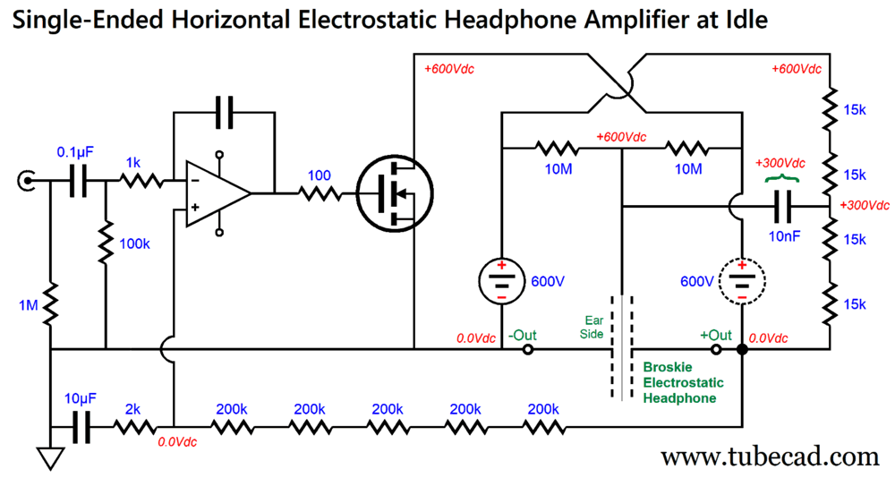
Floating/Fixed Power-Supplies ES Designs
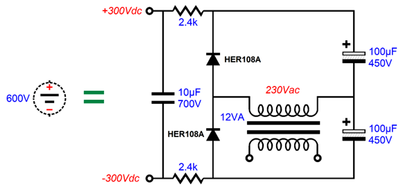
As far as the SiC MOSFET is concerned, nothing has changed from the vertical layouts: same dissipation, voltage and current swings. Each channel requires one floating 600V power supply, but both channels can share a single 600V fixed power supply. Making the 600V floating power supply is easy enough:
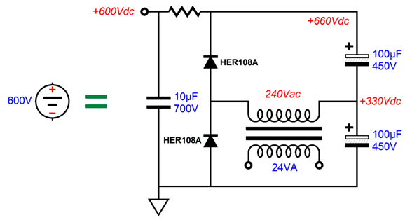
Effectively it is one half of the 1200Vdc floating power-supply. Its brother fixed 600V power supply looks like this:
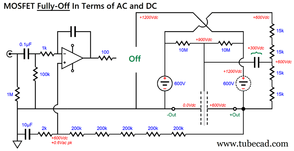
Returning to the amplifier circuit, in order to see how it works we should go to extremes, as in the MOSFET fully off and then fully on.
With the MOSFET no longer drawing any current, the output swings to +600V, as the four 15k resistors relay the +600V from the fixed 600Vdc power supply. Note that the OpAmp inverts the input signal, so a positive input signal is needed to shut the MOSFET off, which means that the entire amplifier is non-inverting. Remember, however, that the ear is near the grounded stator; thus, relative to the ear, the amplifier is inverting. Next, a fulling on MOSFET.
The fully-on MOSFET effectively becomes a dead short. Thus, the floating power supply no longer floats, so the 60k of resistance falls across a 1200V voltage differential, causing 20mA of current flow to be induced. The coupling capacitor attaching to the diaphragm is constantly charged up to +300V at audio frequencies, so it acts as a battery of sorts. It also acts as an RC filter with the two 10M resistors, which provides a low impedance path to half the signal that the driven stator receives. It will also deliver half of the ripple that leaks out of the fixed 600V power supply. Is this a problem? Not really, as the ripple is differentially equal to the two stators, so ignored. This amplifier gain is equal to 1 to (2k + 1M)/2k or 1:501 or +54dB. In other words, 1Vpk of input signal will bring it to full output. The 10µF capacitor that terminates the negative feedback loop resistors ensures low-frequency bandwidth to below 10Hz. (I would add two protection diodes, such as the 1N4148, to bridge the OpAmp's two inputs, so as to prevent latch-up at start-up.) All in all, I quite like the look of this design. The 600V power supplies are just about my maximum voltage with which I feel comfortable in my electronic work. (Remember, twice the voltage, four times the wallop.) I like that the OpAmp operates at ground level and could be DC coupled to the input signal (the AC gain is 1:500, but the DC gain unity). I like how the OpAmp also functions as an auto-bias and DC servo. And, finally, I like the idea of exploiting SiC MOSFETs at long last. MESSAGE TO ELECTROSTATIC HEADPHONE MAKERS: Audeze, Dan Clark, HIFIMAN, Koss, Sennheiser, Stax, Warwick—feel free to adopt any and all of my designs presented here. Credit would be nice, but a pair of Broskie-configured electrostatic headphones would be even nicer still.
Music Recommendation: More 24-Bit, 192kHz
//JRB
Did you enjoy my post? Do you want to see me make it to post 1,000? If so, think about supporting me at Patreon.
User Guides for GlassWare Software
For those of you who still have old computers running Windows XP (32-bit) or any other Windows 32-bit OS, I have setup the download availability of my old old standards: Tube CAD, SE Amp CAD, and Audio Gadgets. The downloads are at the GlassWare-Yahoo store and the price is only $9.95 for each program. http://glass-ware.stores.yahoo.net/adsoffromgla.html So many have asked that I had to do it. WARNING: THESE THREE PROGRAMS WILL NOT RUN UNDER VISTA 64-Bit or WINDOWS 7, 8, and 10 if the OS is not 32-bit or if it is a 64-bit OS. I do plan on remaking all of these programs into 64-bit versions, but it will be a huge ordeal, as programming requires vast chunks of noise-free time, something very rare with children running about. Ideally, I would love to come out with versions that run on iPads and Android-OS tablets.
|
I know that some readers wish to avoid Patreon, so here is a PayPal button instead. Thanks.
John Broskie
John Gives
Special Thanks to the Special 87 To all my patrons, all 87 of them, thank you all again. I want to especially thank
I am truly stunned and appreciative of their support. In addition I want to thank the following patrons:
All of your support makes a big difference. I would love to arrive at the point where creating my posts was my top priority of the day, not something that I have to steal time from other obligations to do. The more support I get, the higher up these posts move up in deserving attention.
If you have been reading my posts, you know that my lifetime goal is reaching post number one thousand. I have 396 more to go. My second goal was to gather 1,000 patrons. Well, that no longer seems possible to me, so I will shoot for a mighty 100 instead. Thus, I have just 13 paying patrons to go. Help me get there. Thanks.
Only $9.95
The Tube CAD Journal's first companion program, TCJ Filter Design lets you design a filter or crossover (passive, OpAmp or tube) without having to check out thick textbooks from the library and without having to breakout the scientific calculator. This program's goal is to provide a quick and easy display not only of the frequency response, but also of the resistor and capacitor values for a passive and active filters and crossovers. TCJ Filter Design is easy to use, but not lightweight, holding over 60 different filter topologies and up to four filter alignments: While the program's main concern is active filters, solid-state and tube, it also does passive filters. In fact, it can be used to calculate passive crossovers for use with speakers by entering 8 ohms as the terminating resistance. Click on the image below to see the full screen capture.
Tube crossovers are a major part of this program; both buffered and un-buffered tube based filters along with mono-polar and bipolar power supply topologies are covered. Available on a CD-ROM and a downloadable version (4 Megabytes). Download or CD ROM
|
|||


| www.tubecad.com Copyright © 1999-2024 GlassWare All Rights Reserved |