| John Broskie's Guide to Tube Circuit Analysis & Design |
24 July 2024 Post Number 605
While I was throwing away a thick wad of old papers, one sheet darted out, as if trying to avoid the trash can. It held a large schematic, which admittedly is not rare in my household, but the schematic was more interesting than usual. I instantly remembered it. Ten years ago, in post 285, I displayed this interesting OTL power amplifier schematic, which I had found in an old electronics book, Keith Henney's Radio Engineering Handbook.
What made this OTL design interesting was that it held zero transformers, zip, nada, none. Imagine a power amplifier chassis that holds only tubes, capacitors and resistors, but no iron, not even a choke. Until the advent of class-D, this tube-based power amplifier was lighter than the equivalent solid-state power amplifier, as transistors require (at the very least) heavy heatsinks. How is that possible? The design rectifies the raw wall AC voltage to create a high-voltage bipolar power supply, while all the tube heaters connects across the outlet's raw AC voltage. This is, of course, crazy Dangerous. Let me repeat myself: DANGEROUS!
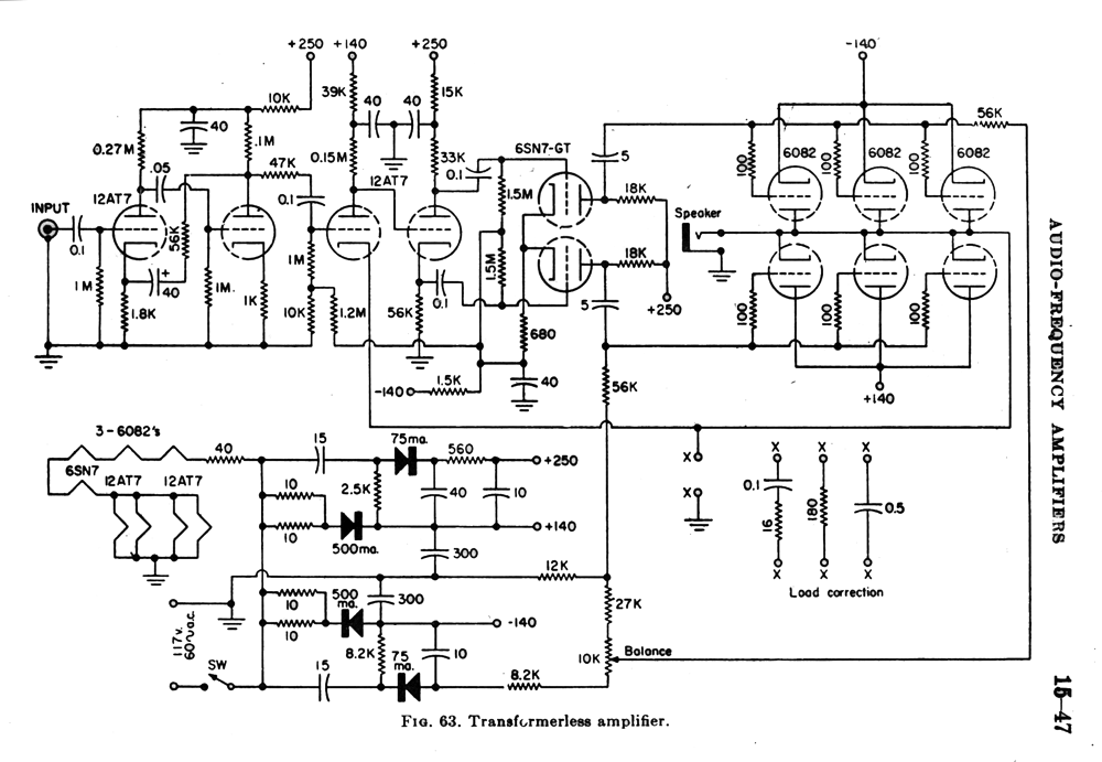
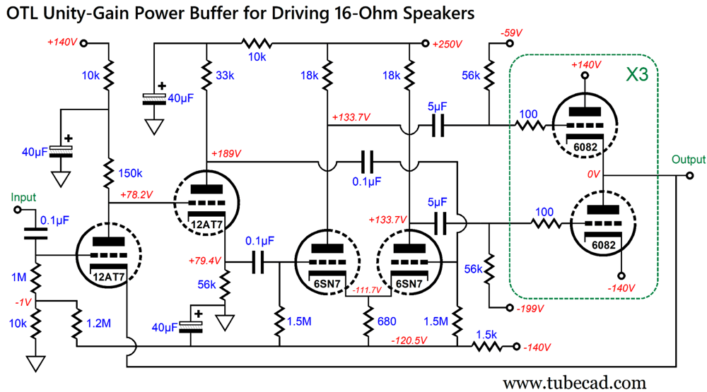
Prior to polarized wall sockets and AC plugs, this old trick produced many shocks; for example, when someone touched a metal water faucet and an electrical device, such as toaster, at the same time, as there was 50% chance that electrical device was grounded to the wrong AC pin. (One of the two AC wires connected to the house ground, which connected to the cold-water pipe, while the other wire was the live wire.) Here is the crazy-dangerous schematic:
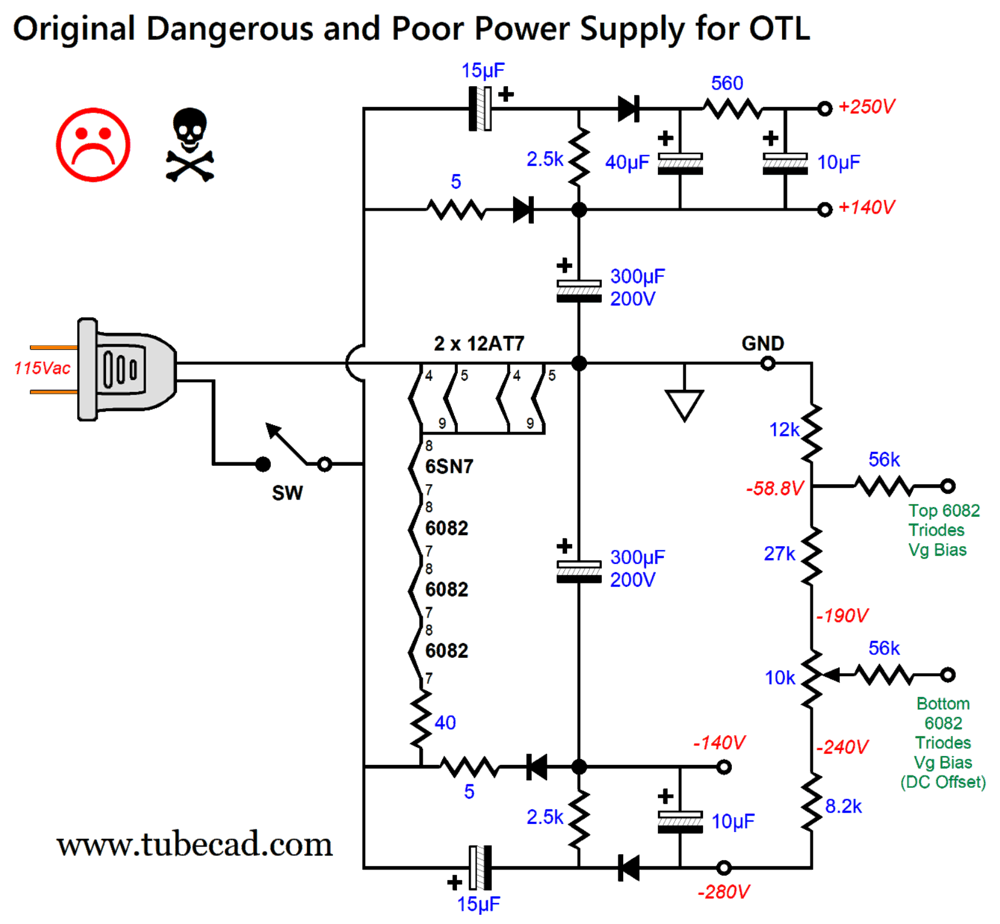
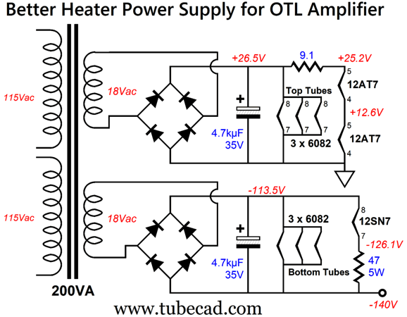
Let me repeat myself: DANGEROUS! This OTL power amplifier was not only transformerless, but also output capacitor-less. The OTL amplifier delivered 25W of average or RMS (50W of peak power) into 16-ohm load, with six 6082 twin-triode output tubes doing the heavy lifting. The 6082 was an industrial version of the 6AS7 twin-triode tube, but with a 26.5V heater element, not the standard 6.3V heater. The 6AS7's heater draws 2.5A of current, while the 6082's draws only 600mA. Both heaters dissipated roughly the same amount of heat, 15.9W for the 6082 and 15.75W for the 6AS7. As schematics go, this is an especially nice one. No doubt, it was crafted by an experienced draftsman. The spacing is particularly fine. After subjecting my eyes to too many patent schematics, it is like a haven of clarity in a wasteland of clutter. Nonetheless, let me redraw the power-supply portion of the schematic, so as to make what is going on clearer.
Note how one AC plug prong is ground. The ±140Vdc bipolar power supply rails are created by the two half-wave rectifiers in series with the 5-ohm resistors (actually two 10-ohm resistors in parallel). The +250Vdc and -280Vdc bipolar power supply rails are created by the two half-wave voltage-doubler circuits. What is odd here is that the 2.5k resistors should be replaced by rectifiers. Why weren't they? Back when this amplifier was designed, solid-state rectifiers were expensive, so a one-penny resistor seemed the better choice. The bias arrangement for the output tubes is interesting. The top triodes see a fixed bias voltage (i.e. no potentiometer), the bottom triode get a bias-adjustment potentiometer, which serves to set the DC offset at the output. Each output triode idled at about 60mA, which against the 140V cathode-to-plate voltage of 140V resulted in around 8.5W of dissipation per triode. The heater elements are in a series/parallel arrangement, which with the 40-ohm series resistor allows a 600mA current flow directly from the wall AC voltage. The 40-ohm series resistor is a nice touch, as it acts as a current-limiter at startup, when the heater elements are cold and present a much lower resistance. In other words, this resistor will extend the heater's lifespan. Note that a wall voltage of 115Vac should rectify up to 160Vdc, not 140Vdc, as 115Vac against 1.414 equals 162.6Vdc, from which we must subtract the rectifier voltage drops. The answer is found in the 5-ohm series resistors and the low efficiency of the old solid-state rectifiers. Using modern rectifiers, we would get the 160Vdc voltage. Indeed, probably more, as the wall voltage has climbed over time and 120Vac is the new standard AC voltage in the USA. Today, we would never build this power supply. (Of course, as soon as I wrote this last sentence I realized that it was wrong, as many today would build this power supply, as they know little of actual modern electronic practice and are slaves to old schematics. If it was good enough for Western Electric in 1944, then it is good enough for me in 2024.) The first step in designing a modern replacement is to forgo the cheat of using the wall voltage directly. In other words, use power transformers.
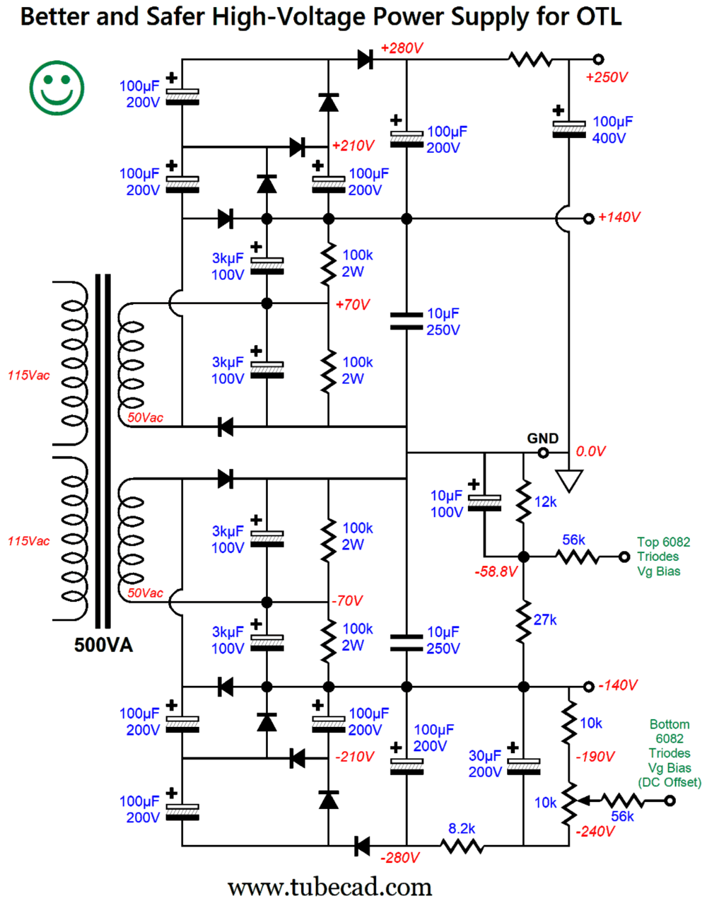
This modern replacement may look like a half-wave rectifier circuit, but the ±140Vdc bipolar power supply rails are created by the two full-wave voltage-doubler circuits. The lower-voltage capacitors are both cheaper and easier to source than high-voltage capacitors. The 3kµF capacitors are effectively in series, so their resulting total capacitance is 1.5kµF, which is five times more than the original 300µF. The 500VA power transformer presents two secondary windings at 50Vac and 5A, which must be halved to 2.5A due to the voltage-doubling rectifier configuration. Where is the heater power supply? Since the original OTL power amplifier was designed to drive 16-ohm loudspeakers, which are rare today, we must double the number of output tubes to drive an 8-ohm loudspeaker. In other words, we must use six 6082 output tubes. Since six is an even number, we can use three 6082 tubes to provide the top six triodes, and three to provide the bottom six triodes.
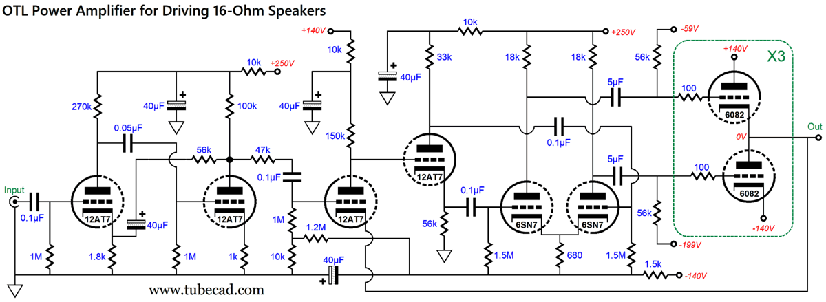
Note that the 6SN7 has been replaced by a 12SN7, whose heater draws 300mA of current. The assumption here is that the wall voltage is 120Vac, not 115Vac. (In 230Vac countries, the secondary voltages should be 20Vac.) A further assumption is that the power transformer is VA rated at 50Hz, not 60Hz, which means that when used with 60Hz wall voltage, the true VA is 240VA. In other words, the heater transformer is a bit under loaded, so the secondary voltages will be even higher. The big advantage of using two power transformers is that it allows us to easily stagger their turn-ons, with the heater power supply coming on line first, then the high-voltage power supply. This sequence greatly protects the tubes, as the cloud of electrons surrounding a hot cathode protects it from the high-voltage power supply slamming on, which otherwise strip away portions of the cathode coating due to the high electrostatic forces on a cold cathode. Before I move on to modifying the OTL amplifier, let's review the original design. I have redrawn the schematic:
It does look complicated, but there actually two amplifiers shown here, each with its own negative feedback loop. The input (and first amplifier) delivers all the signal voltage gain; the second amplifier, all the current gain, as it is a unity-gain power buffer. Let's start with the original input stage:
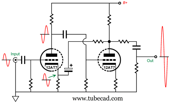
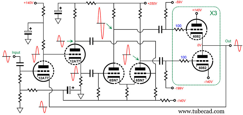
Since two grounded-cathode amplifiers in cascade deliver a non-inverted output signal, the input 12AT7 triode's grid becomes the non-inverting input, while the cathode effectively becomes the inverting input. Thus, the 40µF capacitor and 56k resistor form the negative feedback loop, which sets the gain, lowers the distortion and output impedance of the output signal. Just why the 47k resistor appears in series with the coupling capacitor at the output, I cannot figure out, other than to conclude that it acts as an RC filter following with the power buffer's input capacitance. Speaking of low-pass filters, I find it odd that no input low-pass filter is used; moreover, it's odd that no grid-stopper resistors are employed, other than on the 6082 output triodes, and those grid-stopper resistors are only 100 ohms in value. The frequencies where an amplifier that holds a negative feedback loop is most likely to get into trouble are at the extreme low-frequencies and high-frequencies. The input high-pass filter (the input 0.1µF coupling capacitor and 1M resistor) takes care of the low-frequencies. Adding a low-pass RC filter after the input coupling capacitor would limit the high-frequency bandwidth the amplifier would see, which is always a good idea, as there's no advantage in amplifying ultra-high-frequency hash and RFI. Here are the phase relationships within the amplifier:
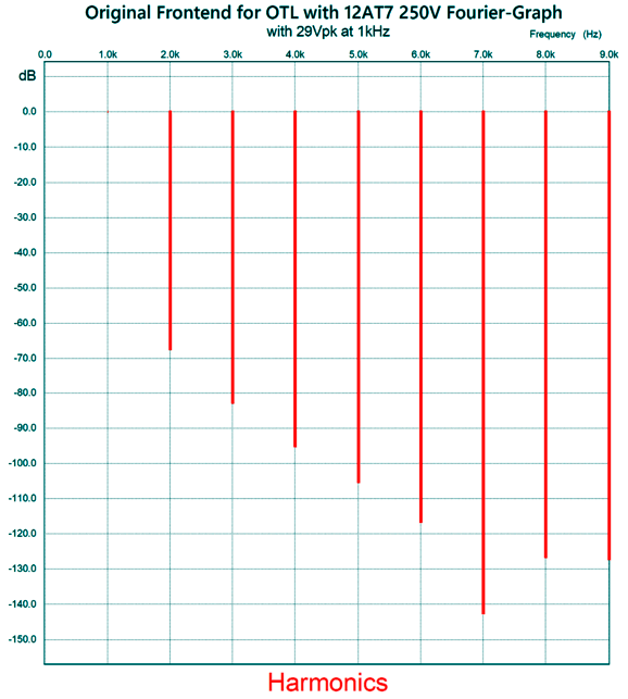
The input triode inverts the signal, but the second triode also inverts, resulting in no phase reversal. Note how the signal at the input triode's cathode and grid equal each other. The way the negative feedback works is that if the signal at the cathode differs from the grid, then the triode will amplify the discrepancy in phase, which the second triode will invert, thereby cancelling the error at the output, as negative and positive cancel. In SPICE simulations, this input stage performed better than I expected. What I had expected to see was low-frequency lumps and bumps. There weren't any. The low-frequency -3dB frequency was 1.5Hz. The phase shift at 20hKz was less than 1 degree. The high-frequency -3dB frequency was 1.5MHz. The gain came in at 1:29 (+29.25dB). With 1Vpk of input signal, resulting in 29Vpk of output, the THD distortion was below 0.1%.
Note the lovely single-ended-like cascade of harmonics, with the 7th being especially suppressed. The PSRR figure was good at -60dB at 100Hz. Mind you, the original power supply will produce lots of ripple due to the small-valued capacitors and the half-wave voltage-doubler circuits. For example, -60dB means divide by 1000, so if 5Vpk of ripple occurs, 5mV of ripple will exit the fronted amplifier. In addition, I dislike the electrolytic capacitor terminating the 56k negative feedback resistor. Sadly, non-polarized electrolytic capacitors top out at 100Vdc voltage rating, as that is what I would want to use here. Replacing the electrolytic capacitor with a film or PIO capacitor would be a good idea. Failing that, we should bypass the electrolytic capacitor with a high-quality film or PIO capacitor, say 0.33µF Let's move on by looking into the unity-gain second amplifier/power-buffer.
The leftmost 12AT7 triode is configured as a grounded-cathode amplifier; the second 12AT7 triode, a split-load phase splitter; and the two 6SN7 triodes, a differential amplifier. The input triode runs on a near-trickle current of only 0.4mA. Note that the input triode's cathode terminates directly into the output, which means 100% negative feedback. If we wanted some signal gain, the signal would have to be attenuated with a two-resistor voltage divider, so the input triode's cathode would only see a fraction of the output signal. Since the power buffer's output is at ground potential (i.e. 0.0Vdc), the input 12AT7 cathode is also at the ground potential, which means that its grid must see a negative-bias voltage. This explains why the 10k and 1.2M are there. The split-load phase splitter breaks with standard practice, as the cathode and plate resistors don't match, with the plate resistor being 33k and the cathode resistor 56k. This results in an imbalanced set of output signals. Why? To give the bottom output triodes less drive signal than the top output triodes. Remember the top triode's cathode must follow the signal at its grid, whereas the bottom-triode's cathode does not see any of the signal that is present at its grid. If a true balanced set of anti-phase signals were delivered to the top and bottom triode's grids, the bottom triodes would grossly be overdriven. In order to get balanced swings from the output triodes we must deliver unequal drive signals to the top and bottom triodes grids.
My take on this unbalanced split-load phase splitter trick is that this is a lazy and lame solution. How so? This trick only works perfectly for one specific load impedance; in this setup, 16 ohms. The huge problem is that most loudspeakers are anything but flat in impedance, their impedance plots looking more like an outline of a rollercoaster track. An optimal solution requires a dynamically adjusting ratio of drive signals for the top and bottom triodes, regardless of the load impedance, from zero to infinity. One fixed size does not fit all, but a dynamically-adjusting size does. Note the huge-valued (5µF) coupling capacitors that attach to the output tubes. Why so big? Perhaps, it was just a typo, with 0.5µF being the actual values. Another possibility is that the large-valued capacitors were needed to prevent capacitor overcharging of coupling capacitors when the output tubes are overdriven and the grids begin to draw current. Normally, 10k grid-stopper resistors would connect to the 6082's grids, as they would greatly limit the instantaneous over-charging of the coupling capacitor that leads to blocking distortion, wherein the output tubes briefly turn off completely, as they see too great a negative bias voltage. The greater the capacitance, the more current will be needed to over-charge that capacitance. Let's look at the phase relations within the power buffer:
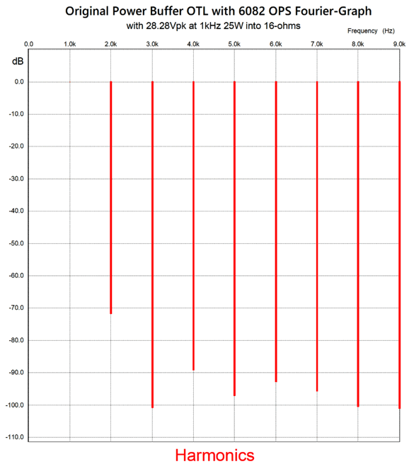
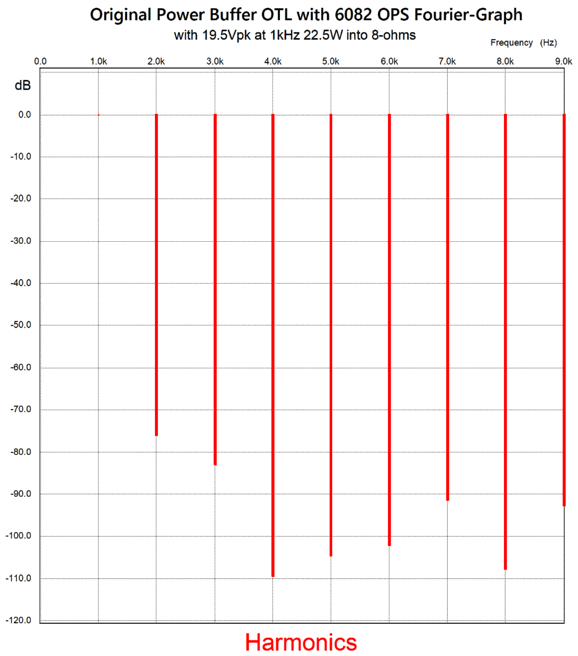
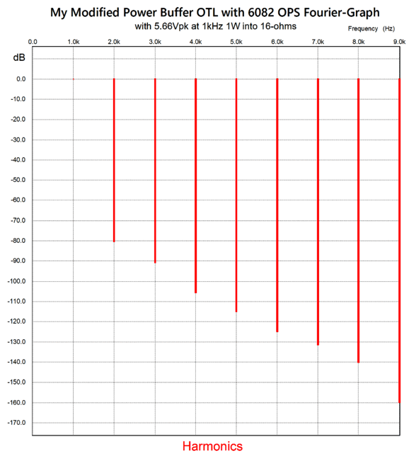
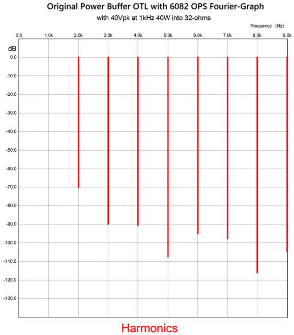
Note the bigger signal for the top output triodes. In SPICE simulations, the split-load phase splitter's unequal cathode and plate resistors did the trick for a 16-ohm load, as the current conduction between top and bottom output triodes was well balanced. The maximum output voltage swing into 16 ohms was 28.28Vpk, which equals 25W, as 25²/(16 Ohms x 2) = 800/32 = 25. I expected this much output power. My reasoning was that a 6082 (i.e. a 6AS7), with a cathode-to-plate voltage of 100V and cathode-to-grid voltage of 0V, will draw about 550mA. (A factoid I have memorized, as it is useful in designing OTL amplifiers.) Well, three 6082 triodes working in parallel, with a B+ voltage of 140Vdc, should be able to deliver 2A of peak current, which would give us over 25W (average, not peak) watts into a 16-ohm load. To get 25W requires 28.28Vpk voltage swing and 1.77Apk current swings from the output stage. In SPICE simulations, I had to add an RC low-pass filter made up of a 470-ohm resistor and 300pF capacitor at the input and load the output with a 1-ohm resistor in series with a 0.1µF capacitor to prevent high-frequency oscillations and stalled simulations. The results were amazingly good, far beyond what I expected. Here is the Fourier graph for full output, i.e. 25W at 1kHz into a 16-ohm load
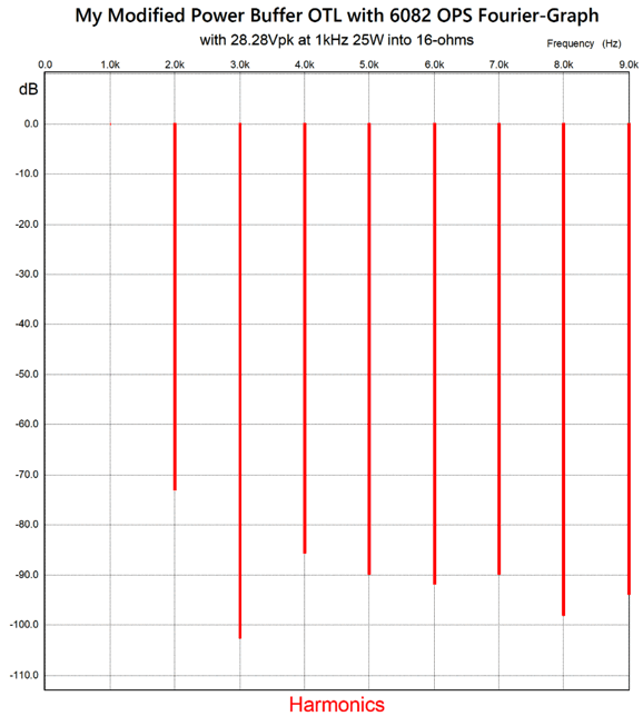
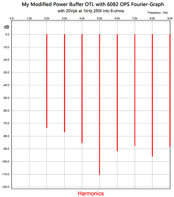
Note the glorious suppression of the 3rd and 5th harmonics. The THD translates to less than 0.1%, which is dang impressive. Of course, reality would prove somewhat worse. Why? Remember that SPICE power supplies are perfect, whereas real power supplies are dirty and limited. I bet it could deliver 25W—for a while—before its power-supply rail voltage collapsed. (Remember the 5-ohm resistors in series with the rectifiers.) I wondered how well it would perform with 25W of output into an 8-ohm loudspeaker (20Vpk). Not so good, as it would only deliver 19.5Vpk before going into positive-grid conduction. In addition, the current conduction between top and bottom output tubes was imbalanced. This translates into 22.5W, which is still a lot for so few output tubes.
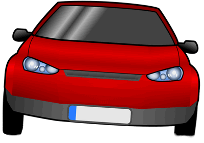
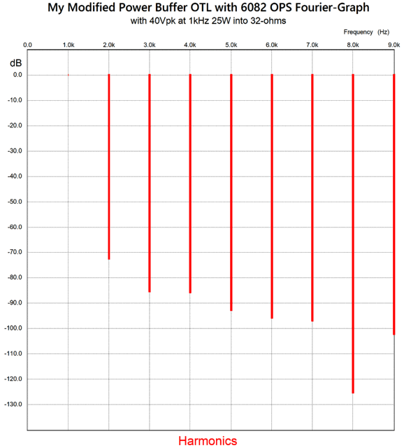
I also tried a 32-ohm load and 40Vpk voltage swings, with similar results, i.e. not as good as the 16-ohm. With a decrease in the load impedance we expect things to get worse, but with an increase in impedance things should get better, as the amplifier is less taxed. What is going on here? This is the result of the lazy static solution employed to deal with the unequal drive requirements for the top and bottom output triodes. The analogy I have made before was that of a car that had larger tires on the right than on the left side. The static solution might be to under-inflate the tires on the right, while over-inflating those on the left. As long as the car was parked, this lazy solution would work just fine.
What would a dynamic solution to deal with the unequal drive requirements for the top and bottom output triodes look like?
We start with the split-load phase splitter delivering a true balanced output, and then we use the differential amplifier to dynamically correct for the differing drive voltages for the top and bottom output triodes. Note that the added electrolytic capacitor on the left terminates into the output; the one on the right, to the -140Vdc power-supply rail. The result is that both the top and bottom triodes function as grounded-cathode amplifiers. That's right grounded-cathode amplifiers, not a cathode follower and a grounded-cathode amplifier. Imagine that we break the negative feedback loop and quickly place a D-cell battery in place of the loudspeaker. The top triode's cathode is forced up by 1.5V, while its grid is also forced up by 1.5V, as the electrolytic capacitor that bridges the output to the differential amplifier relays the positive pulse through the coupling capacitor to the top triode's grid. In other words, as far as this top triode is concerned the difference is that its B+ voltage has fallen by 1.5V. As far as the bottom output triode is concerned, the only difference is that its B+ voltage has risen by 1.5V. Both output triodes only offer their plate resistance (rp) to oppose the positive pulse. Next, let's examine the added electrolytic capacitor on the right that terminates into the -140Vdc power-supply rail. Why not ground? Enhanced PSRR is the short answer. The -140Vdc power-supply rail delivers current to the output-stage triodes; it's going to carry a lot of ripple, especially with the half-wave rectification. A triode's cathode functions as the triode's non-inverting input; in addition, it actually delivers a slightly higher gain than the grid, as it exhibits slightly higher transconductance, (mu + 1)/rp versus mu/rp. With a 12AX7 this makes little difference, as its amplification factor (mu) is 100. But with a 6AS7, the difference is huge, as its mu is only 2. The added electrolytic capacitor on the right that terminates into the -140Vdc power-supply rail relays the ripple at the -140Vdc power-supply rail to the bottom triode's grid. In other words, the cathode and grid will see 100% of the ripple, so there is effectively no signal to amplify. By the way, this modified differential amplifier requires a balanced set of anti-phase signals that are equal in amplitude, which brings us back to the split-load phase splitter. (When designing preamps, we begin at the input and design our way to the output. When designing power amplifiers, we do the opposite: starting at the output and working are to the input.)
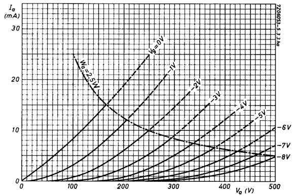
I don't like running tubes at trickle current. In fact, I have a reputation for having lead foot when it comes to setting idle current. I am guilty as charged. Examine the following set of plate curves for the 12AT7/ECC81 triode. The bottom horizontal line marks zero mA. The next line up marks 1mA. The original setup had the input triode idling at a wee 0.39mA. Next note the poor linearity below 1mA. In contrast, my modified version (shown above) increases the idle current to 1.7mA, which is still low, but four times greater than the original.
The added Aikido-Mojo parts improve the PSRR by ensuring that both of the split-load phase splitter's outputs carry the same amount of ripple and in phase with each other. The following differential amplifier offers a poor common-mode rejection ratio (CMRR), but will equally amplify the ripple signal, which the output triodes will then null at the output. (Well, they will produce the null as long as they are still operating in the class-A window of current conduction.) The original frontend circuit and, to a lesser extent, this Aikido-Mojo version suffer from high-frequency instability when combined with the differential and output stage. Part of the problem is that 100% negative feedback is hard to pull off with any amplifier. For example, most of the chip power amplifiers, such as the LM1875 and LM3886, require minimum gains of 1:10 (20dB) to ensure stability. The more stages in cascade the more difficult it becomes to use a global negative feedback loop due to compounding phase shifts. On the other hand, we could let the differential amplifier function as the phase splitter.
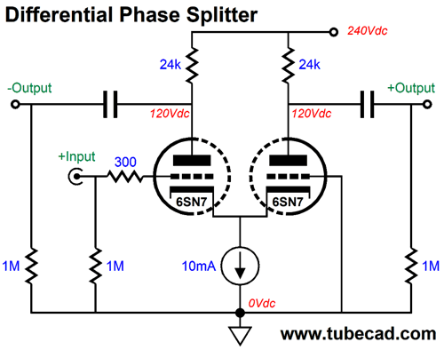
An unbalanced input signal comes out a balanced pair of signals. This circuit is sometimes called a long-tail phase splitter due to the high-valued shared cathode resistor that terminates into a negative power-supply rail. In this example, a constant-current source takes the place of the resistor. When we do use a shared cathode resistor, the plate resistors values must differ to obtain balanced outputs
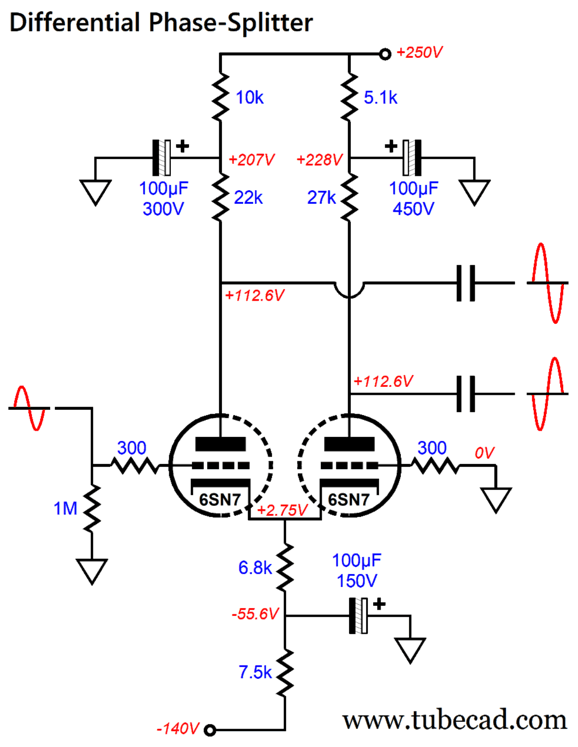
Note that the 22k and 27k plate resistors do not match; if they did match, the two outputs would not match in amplitude. If we replaced the 6.8k cathode resistor with a constant-current source, the imbalance decreases substantially. Note that the right 6SN7 triode's grid is grounded. Well, this grid can also be used as an inverting input; and, thus, it can be used as a negative feedback input. From post 471:
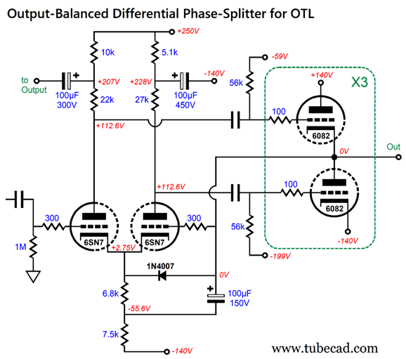
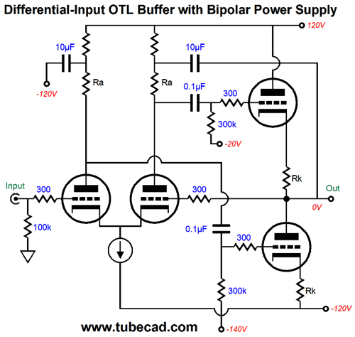
In the following circuit, the output is given to the right 6SN7 triode's grid at full strength and DC coupled. The super-short negative feedback loop lowers the distortion and output impedance.
The added 1N4007 diode protects the 6SN7 at turn-on. The 100µF/300V electrolytic capacitor is not ground terminated, but attaches to the buffer's output. This arrangement dynamically adjusts the balanced drive of the top and bottom triodes. Yes, this is a power buffer, as no signal gain is realized. Since we no longer need a balanced input signal to drive the differential amplifier, we can design a new input stage. I can think of many possible designs, but how about a simple cathode-coupled amplifier?
The 12AT7-based cathode-coupled amplifier delivers an in-phase output signal. In addition, it too employs 100% feedback of the power buffer's output. Note how the 12AT7 and 6SN7 "travel" with the input and output signal. "Travel" in the sense that their grids and cathodes follow the input signal. The result is that we still have a unity-gain power buffer that relies on the input amplifier stage to deliver the signal gain. How well does it perform? The input cathode-coupled amplifier effectively halves the gain from the original version of the grounded-cathode amplifier followed by the split-load phase splitter. Here is the SPICE-generated graph for 1W output at 1kHz into 16 ohms from just the power buffer.
I love the very single-ended look of this cascade of harmonics. The output impedance was a low 0.18 ohms, whereas the original version deliver an even lower 0.11 ohms output impedance. At full output, the distortion is still low.
Looks a lot like the original, which is amazing considering the reduced open-loop gain. Next, we see the Fourier graph for the modified version driving an 8-ohm load.
The next test is with 32-ohm loads.
Let's compare this to the original circuit with a 32-ohm load.
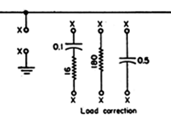
The reduced 5th harmonic is particularly nice. The problem is that SPICE simulations will only take us so far, as the assumption of perfect power supplies is enough to introduce huge doubts. For example, real OTL power-supply rails will begin to collapse under heavy output current demand, which will cause the bottom output-triodes' cathodes to rise positively in voltage, making their grid-bias effectively far more negative. In my modified version, however, the bias voltage will track this positive upward swing. In other words, the 1W output tests are more reliable in SPICE simulations, as the power supplies are not as taxed. But the bigger problem is high-frequency instability. In the original schematic, we saw three different load-correction networks to attach to the output and ground:
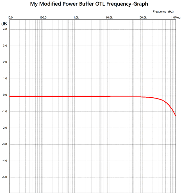
In my SPICE simulations I found that 1-ohm and 0.1µF worked best with the original circuit, but my modified circuit didn't need any. Bear in mind that this is with ideal resistance loads. With squirrelly loudspeaker impedances, who knows what will work best. By the way, here is the frequency plot for my modified power buffer.
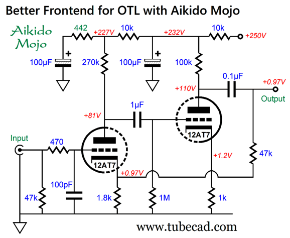
As we can see, the -3dB high-frequency cutoff frequency is over 1MHz. Returning to my alternative heater power supply, we see that I show twice as many 6082 output tubes. Why? The assumption was that most would want to drive 8-ohm loudspeakers, so I doubled the number of output tubes. Strictly speaking, we need only increase the number by the square-root of 2 (1.414) when we halve the load impedance. The problem is that three times 1.414 gives us 4.242 number of tubes. What we need is an even integer, as the 6082 is a twin-triode tube. In addition, most nominally 8-ohm loudspeakers actually dip much lower in impedance at some frequencies. Thus, six 6082 output tubes seems a reasonable number. Returning to the first amplifier input stage, here is my modified version.
No more 40µF electrolytic capacitor in the negative feedback loop; instead, the loop terminates after the output coupling capacitor. In order for this arrangement to work, the time constants between the internal and output coupling capacitors must be carefully staggered. This explains why a 1µF internal coupling capacitor was used. Note the DC offset voltage of 0.97V at the output, which means that the unity-gain power buffer needs to hold its own input coupling capacitor. Or, we can retain the original topology of the buffer's input stage, but use a larger cathode resistor to absorb the DC offset.
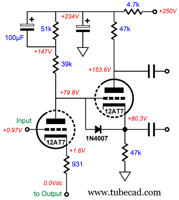
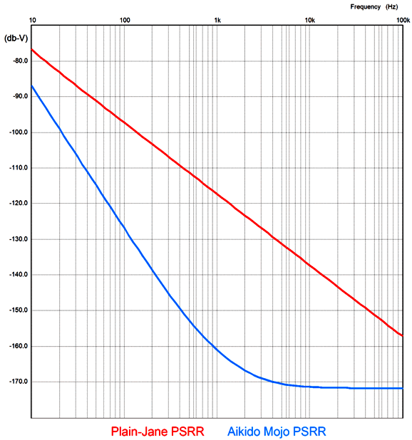
Returning to my modified version of the first input stage, the added 442-ohm Aikido-Mojo resistor improves the PSRR substantially, which the following graph reveals. The red plotline is without the resistor, the blue with the resistor.
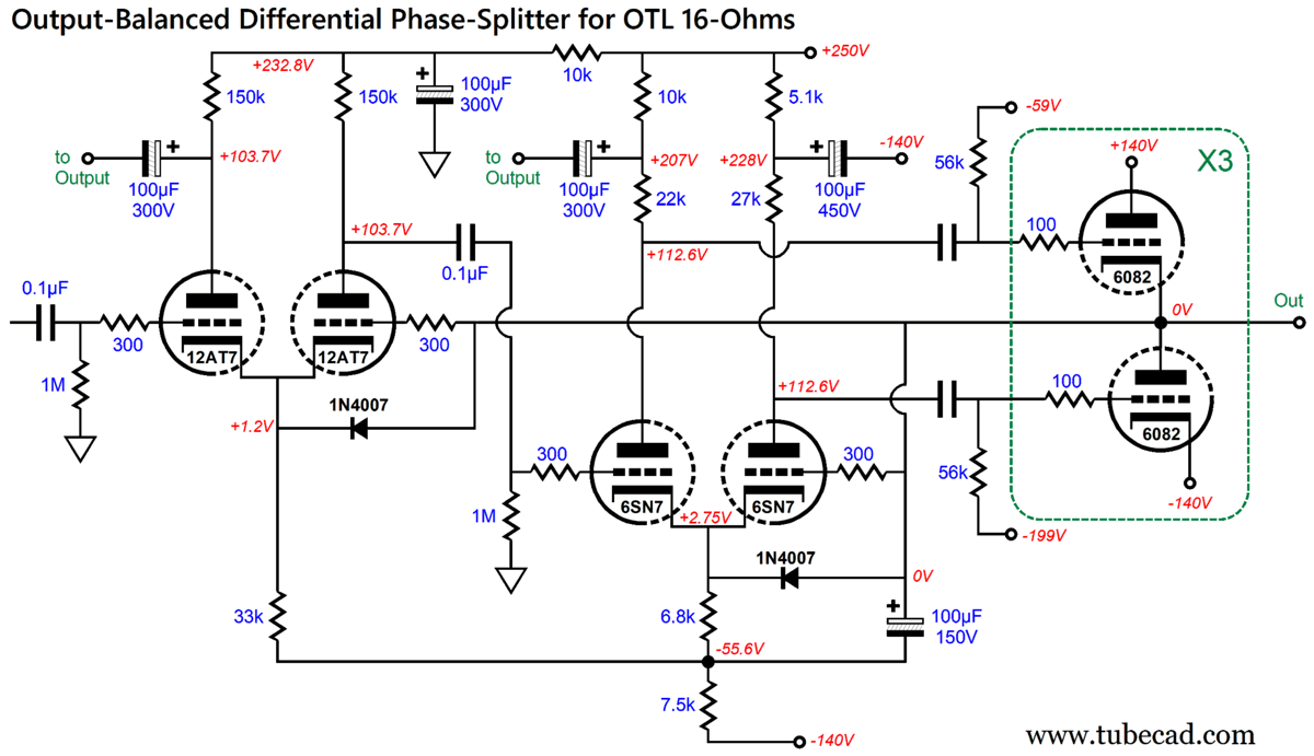
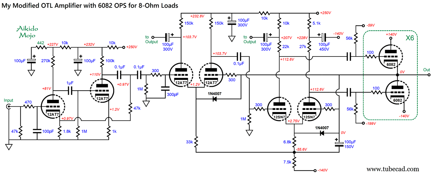
Okay, let's put it altogether:
We see the same arrangement of two circuits in series: the first holds its own negative feedback loop and delivers the entire signal gain; the second, also holds a negative feedback loop and delivers all the current gain, but no signal gain. Bear in mind that my goal was to retain as much of the original circuit as possible; thus, we don't see any tube substituting other than the (12SN7 for the 6SN7) or changes in power-supply rails. My take is that if we use a tube-based line-stage amplifier with a gain of 30dB (i.e. 1 : 31.6), we can forgo the first stage altogether. In addition, the cathode-coupled amplifier input stage for the power buffer might be replaced by a cascode amplifier. What I would absolutely do, however, is bump up the 250Vdc power-supply rail voltage increasing it to at least 350Vdc.
T.S. Eliot wrote in his famous poem, The Love Song of J. Alfred Prufrock,
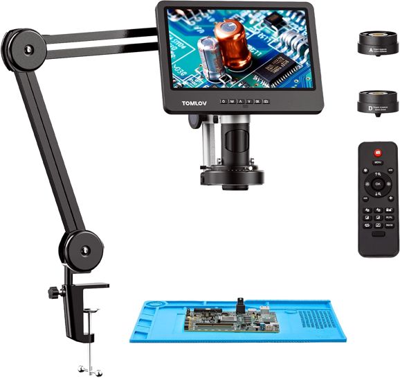
Well, I also grow old, but I will leave my trousers unrolled. What I need is better close-up sight. Thus, when I saw that a sub-category of LCD video microscopes was solder aids, I was intrigued.
Yes, we can use a large magnifying glass, which would be cheaper. The problem with this alternative is that the magnifying glass must go between my eyes and the circuit board. In addition, to get the best focus, my head position is critical. In contrast, the video camera gets out of the way and the screen can be viewed in-focus at any distance. Right now, my procedure is to review my just-soldered PCB with a 10X jeweler's eyepiece, which often reveals questionable solder joints. This might be the best solution. PS: I just bought it. Review to follow soon.
Music Recommendation: More 24-Bit, 192kHz
It's time to reveal classical-music recordings at Amazon Music in 24-24, 192kHz. Be sure to check the actual resolution, as the high-res versions sometimes are replaced by lower-res versions. When I complied this list, they were all 24-Bit, 192kHz.
Anna Fedorova, Storyteller
Bruckner, Symphonies Nos. 6 & 9
Un Milagro de Fe
The Planets - Zubin Mehta, LA Philharmonic Orchestra
Contrasts in Concerts
Mariam Batsashvili, Romantic Piano Masters
Tchaikovsky, Symphony No. 4 & Leshnoff Double Concerto for Clarinet and Bassoon
Sault, Air and Aiir
//JRB
Did you enjoy my post? Do you want to see me make it to post 1,000? If so, think about supporting me at Patreon.
User Guides for GlassWare Software
For those of you who still have old computers running Windows XP (32-bit) or any other Windows 32-bit OS, I have setup the download availability of my old old standards: Tube CAD, SE Amp CAD, and Audio Gadgets. The downloads are at the GlassWare-Yahoo store and the price is only $9.95 for each program. http://glass-ware.stores.yahoo.net/adsoffromgla.html So many have asked that I had to do it. WARNING: THESE THREE PROGRAMS WILL NOT RUN UNDER VISTA 64-Bit or WINDOWS 7, 8, and 10 if the OS is not 32-bit or if it is a 64-bit OS. I do plan on remaking all of these programs into 64-bit versions, but it will be a huge ordeal, as programming requires vast chunks of noise-free time, something very rare with children running about. Ideally, I would love to come out with versions that run on iPads and Android-OS tablets.
|
I know that some readers wish to avoid Patreon, so here is a PayPal button instead. Thanks.
John Broskie
John Gives
Special Thanks to the Special 89 To all my patrons, all 94 of them, thank you all again. I want to especially thank
I am truly stunned and appreciative of their support. In addition I want to thank the following patrons:
All of your support makes a big difference. I would love to arrive at the point where creating my posts was my top priority of the day, not something that I have to steal time from other obligations to do. The more support I get, the higher up these posts move up in deserving attention.
If you have been reading my posts, you know that my lifetime goal is reaching post number one thousand. I have 401 more to go. My second goal was to gather 1,000 patrons. Well, that no longer seems possible to me, so I will shoot for a mighty 100 instead. Thus, I have just 16 patrons to go. Help me get there. Thanks.
Only $12.95 TCJ My-Stock DB
Version 2 Improvements *User definable Download for www.glass-ware.com
|
|||


%20Small.png)


| www.tubecad.com Copyright © 1999-2024 GlassWare All Rights Reserved |