| John Broskie's Guide to Tube Circuit Analysis & Design |
14 August 2024 Post Number 606
Balanced Audio
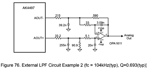
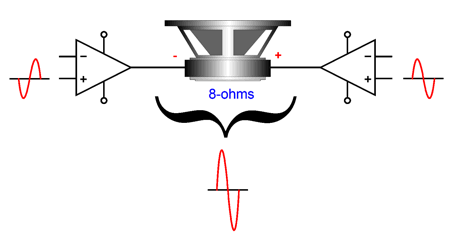
In order to preserve the balanced signal from the DAC, we need only duplicate the circuitry to the right of the DAC, but flip its connections to the DAC. In other words, the 33.2-ohm resistor would attach to the inverting output, while the 215-ohm resistor attaches to the non-inverting output. The question many audiophiles, including me, ask themselves is, Since the XLR jacks are there, what can I do with them? The obvious answer is to buy a balanced line-stage and balanced power amplifier. Not cheap. Another possibility, however, is to buy another unbalanced stereo power amplifier. This way, each loudspeaker gets its own mono-block bridged power amplifier, as the balanced signals drive the two internal power amplifier in anti-phase.
The bridge-amplifier configuration potentially results in quadrupling the power output. In other words, a 100W & 100W stereo power amplifier could deliver 400W into one loudspeaker. The words "potentially" and the "could" enter the picture as each internal power amplifier effectively sees a 4-ohm load, in spite of the loudspeaker being an 8-ohm type. A well-built and designed solid-state power amplifier will deliver twice the power output into a 4-ohm load as it does into an 8-ohm load. Thus, two doublings gives us a fourfold increase. Put mathematically, to get 100W into an 8-ohm load requires 40Vpk voltage swings; since the two internal power amplifiers are driven in anti-phase, the voltage swing the single loudspeaker sees is 80Vpk, which equals 400W into an 8-ohm load, as Vpk²/(2 x Rload) = Watts, or 80²/16 = 400. In contrast, if a 100W solid-state power amplifier delivers only 150W into a 4-ohm loudspeaker, then when two are bridged we only get 300W driving an 8-ohm loudspeaker. If you own 4-ohm loudspeakers, then it is best to avoid the bridge configuration altogether. Another possible use of balanced output signals is to use one phase of signals for the main loudspeaker amplifiers, while the other phased signals drive the subwoofer power amplifiers. (We must reverse the cable connections to the subwoofers to undo the inverted phasing.) Or, we could send the anti-phase signals to a headphone amplifier, thereby avoiding extra switching or unplugging and plugging interconnect cables. A other still possible use is to use a polarity switch to choose between the anti-phase outputs, so we can flip the phase as needed. Post 583 includes more possible uses for balanced signals. In short, having an extra set of output signals can prove handy. In fact, I am stunned that those standalone DACs that sport XLR jacks do not also offer two sets of RCA output jacks, one pair of non-inverting left and right and one pair of inverting left and right RCA jacks. The de facto standard for DAC signal output level is 2Vpk, which is easily enough to drive most power amplifiers to full output. Throw in a remote control for the DAC, and the need for a high-gain (or any gain at all) line-stage amplifier (i.e. preamp) vanishes. We can get extra fancy by adding a unity-gain tube-based buffer to the DAC's outputs, thereby inducing some added sweetness and possibly greater output current delivery.
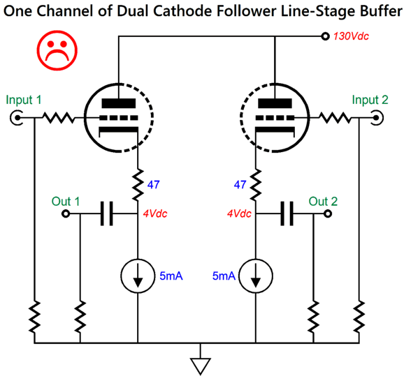
This is pretty much what I do with my own system, as my line-stage runs unity-gain cathode follower outputs, two per channel, so the main power amplifiers get their own set of cathode followers, while the subwoofer amplifiers get their separate set of cathode followers, which prevents interaction between the two. My line-stage buffer also holds an input selector switch and my three-knobbed ladder stepped-attenuator, along with a staggered- power switch. If I didn't also play LPs, I could do away with four switches, leaving only the power switch. See post 588 for more details on my design. Well, all this got me thinking about how to design a dual-cathode-follower circuit that didn't use a high-voltage bipolar power supply, as my line-stage buffer does, but a relatively low high-voltage monopolar power supply—for example, such as the power supplies in some of my 12Vac designs. The hard part will be achieving the same excellent PSRR that the bipolar power supply delivers with a monopolar power supply. With the bipolar power supply, as long as the ripple is equal and in anti-phase on both power-supply rails, we can force a power-supply-noise null by carefully selecting the two cathode resistors values.
Quote from post 588:
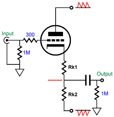
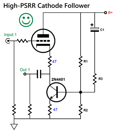
With a monopolar power supply, however, we cannot use this trick. Instead, we must get extra sneaky. Let's start with two cathode followers, each loaded by a solid-state constant-current source at its cathode.
The unhappy face is due to the relatively poor PSRR figure. From post 295:
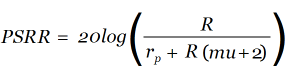
When we replace the cathode resistor with a constant-current source, the formula reduces to 20log(1/(mu + 2)). In other words, the cathode follower will leak ripple/(mu + 2) at its output. The workaround is found in tweaking the solid-state constant-current source.
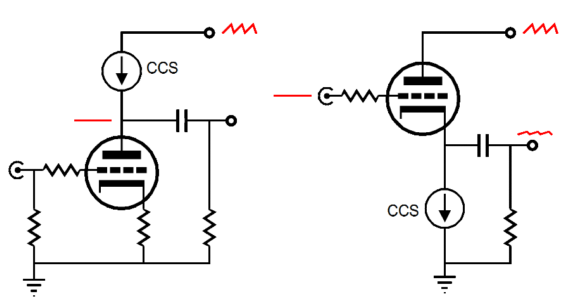
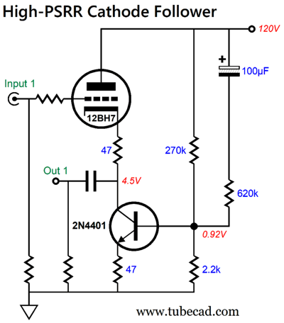
If we leave capacitor C1 and resistor R3 out, we have a simple constant-current source formed from the NPN transistor and its emitter resistor. What capacitor C1 and resistor R3 do is to leak additional power-supply noise into the transistor's base, thereby creating an anti-phase current conduction to the ripple, which in turn will force a ripple null at the cathode follower's output. Obviously, the values for capacitor C1 and resistor R3 will depend on the tube used and the B+ voltage. Here is a design example that uses a 12BH7.
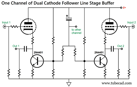
The 12BH7 draws 5mA of idle current. The 47-ohm cathode resistor is there to buffer the cathode from high-capacitance loads, such as long interconnect cables. One fear I had was that at startup, the 100µF capacitor must be charged up through resistor R3, which means that the capacitor is effectively a dead short for a short while; thus, resistors R1 and R3 are effectively in parallel, which could potentially develop too great a base voltage on the NPN transistor. Not to worry, as the lowest value for R3 was found to be 180k, with use of an E182CC tube, making for a combined resistance of 108k, which is still plenty high enough. In other words, no protection zener is needed. Adding an additional cathode follower to each channel is easy enough.
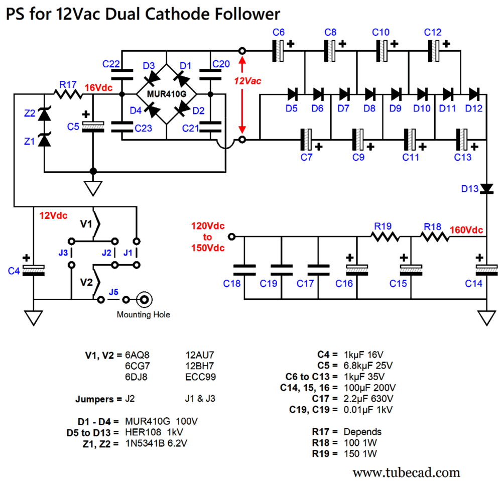
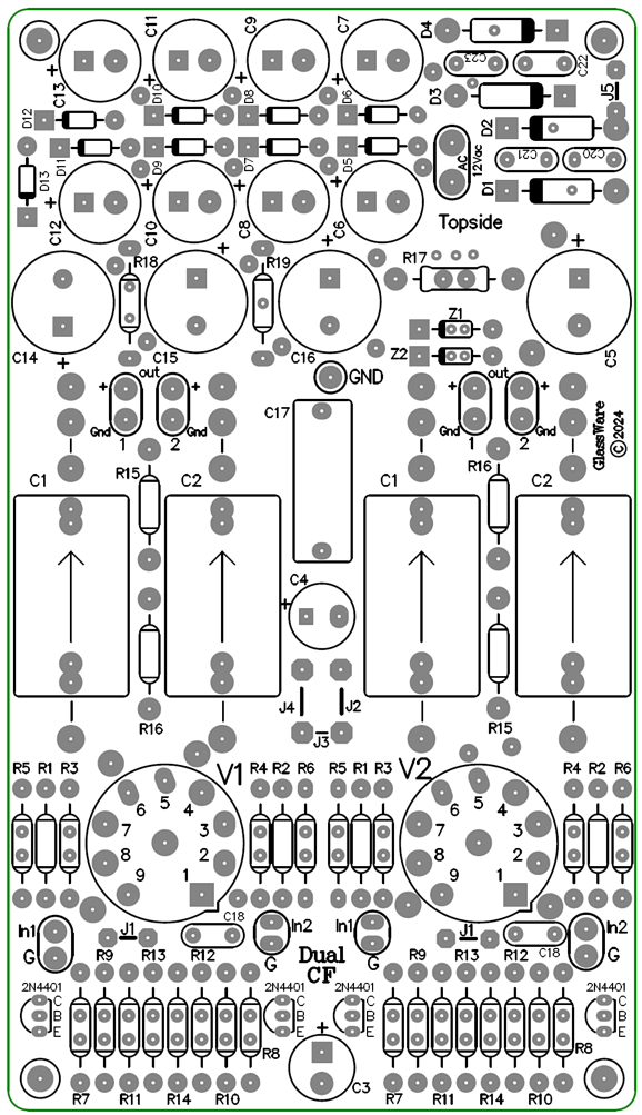
The large-valued electrolytic capacitor can be shared not only between two cathode followers, but between two channels of buffers. I so like this design that I laid out a PCB for it. The 2N4401 is a general-purpose NPN transistor with an Ft of 250MHz and less than 7pF of base-to-collector capacitance. Of course, other transistors could be used, but there's no real need for high-voltage transistors, as the cathode voltages are so low. The accompanying power supply is powered by either a 12Vac wallawart or a 12Vac power transformer. The key descriptor in this last sentence is "12Vac," as 12Vdc switching power supplies will not work. (It seems that I cannot ever repeat this too often, as the distinction between AC and DC eludes many.)
Both the heater and high-voltage power supplies are full-wave types. The two 6.2V 5W zeners in series form the shunting regulator for the heater power supply. Either 6-volt tubes, such as the 6CG7 and 6DJ8, or 12-volt tubes, such as the 12AU7 or E188CC, can be used by selecting the correct jumpers.
Four cathode followers and 12Vac powered power supply on one board, a relatively small board at that (4in by 7in). I haven't actually pulled the trigger, however, and ordered a production run of the PCB. (Since I do not use auto-routing—ever—laying out a PCB is close to being an art form and logic puzzle at once.)
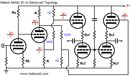
Unbalanced to Balanced Out
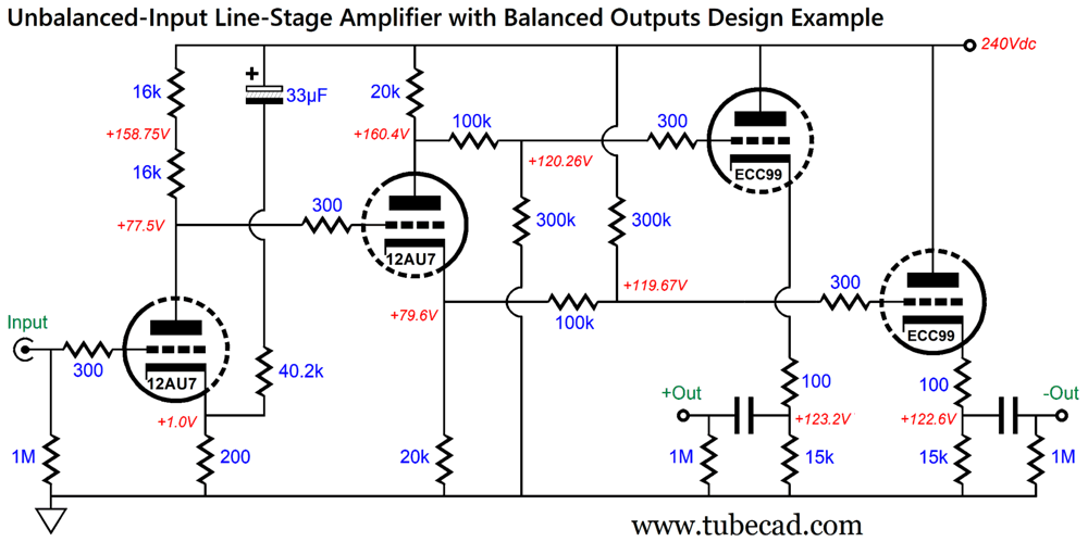
The circuit turns an unbalanced input signal into a set of balanced outputs. In addition, it offers a greatly-enhanced PSRR and low output impedance. No internal coupling capacitors are used, just two output coupling capacitors. The Aikido mojo is found in the mathematical ratios within the circuit. (Read the post for more details.) I wondered if I could simplify the circuit by losing one tube (i.e. two triodes). What we would be giving up is stellar PSRR, as the dual Aikido-cathode-follower output stage forced a power-supply-noise null at the outputs. Without the Aikido-cathode-follower output stage, the PSRR falls to just -6dB. Is this the end of the world? No.
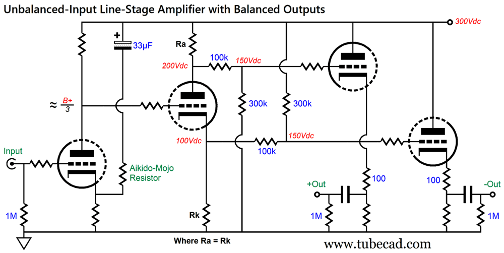
If the unbalanced-to-balanced line-stage amplifier drives a balanced power amplifier, the power amplifier's own intrinsic common-mode rejection (CMRR) produces a deep power-supply-noise null at the loudspeaker. Well, it does provided that each output shares the same amount of power-supply noise. If they differ, the difference will be amplified. For example, say the inverted output delivers 0.4mV of ripple, while the non-inverting output leaks 0.5mV of ripple, the balanced amplifier will treat the 0.1V of difference as a signal to amplify. The workaround is to add some fine-tuning adjustment.
The Aikido-mojo resistor and 33µF capacitor allow for such fine tuning. Ideally, we want 2/3 of the power-supply noise to appear at the split-load phase splitter's plate and 1/3 to appear at its cathode. The 3/4 voltage divider attaching to the plate will reduce the noise to 1/2, while the voltage divider attaching to the cathode will increase the noise to 1/2. Equality, parity, uniformity. Of course, we will still try to deliver the cleanest B+ voltage possible, but it is reassuring to know that whatever remaining trickle of power-supply noise present will be equally superimposed upon the two output signals. Here is a fleshed-out design example:
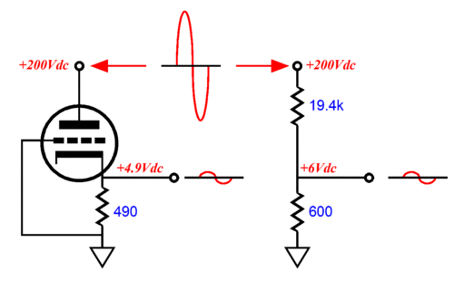
Note that the grounded-cathode amplifier input stage uses two plate resistors in series. This arrangement not only splits the heat dissipation, but also allows mixing two 5% resistors to obtain the desired load resistance; in this example, no 32k 5% resistors are made, but the two 16k 5% resistors are made. Other than the 40.2k Aikido-mojo resistor, all the other resistors can be 5% types. Of course, the best results obtain with tightly matched resistors, no matter what the tolerance. The beauty of this arrangement lies in that as we change the Aikido-mojo resistor's value, all the voltage relationships within the circuit remain unaltered. Another approach to deriving a balanced output from an unbalanced input signal is to use an audio-signal output transformer.
The signal transformer does not need to hold an airgap, as no DC current flows through its primary. By carefully selecting the input stage's plate and cathode resistor values we can deliver 50% of the B+ voltage ripple to both ends of the primary, which means the transformer will ignore the ripple. Note how the two capacitors define a 50% AC voltage divider; in addition, they serve as part of the RC filtering for the B+ voltage. A twofer, in other words. By the way, these two capacitors do not have to be film or PIO, as two low-ESR, high-frequency electrolytic capacitors can be used instead. (I would still bypass the electrolytic capacitors with high-quality film capacitors.) Note that the transformer's secondary is completely floating (i.e. not connected to ground); this arrangement elegantly sidesteps grounding problems. Each 1:1 signal transformer will have an optimal load impedance. Often, this impedance is a low 600 ohms. I have seen 15k, 20k, and 22k as alternative resistances. Whatever the optimal load impedance is, give the transformer it. For example, if the power amplifier uses two 47k input resistors, making a combined resistance of 94k, and the optimal load is 20k, we would place 25.5k resistor across the secondary leads, bringing the load impedance down to 20k.
In this design example, we see 6SN7 configured in a constant-current-draw amplifier (CCDA), which greatly unloads the B+ voltage in terms of AC, as the two triodes current swings move anti-phase, thereby delivering a constant current flow. Ready for this? Even if they differed in current conduction, the two-capacitor voltage divider will force an output null of whatever AC signal that appears on the B+ voltage rail. One fear I have is that the output transformer might saturate at startup, as the two big-valued capacitors charge up. We can add two zeners to protect the primary from an over-voltage.
The two 6.2V zeners impose a peak voltage clamp of about 7V across the primary, which in turn would force the same 7V peak differential voltage swing on the secondary. Is this a problem? Not likely, as most balanced power amplifiers only need a peak differential input voltage swing of 2V to achieve full output.
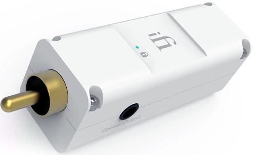
iFi SPDIF iPurifier2
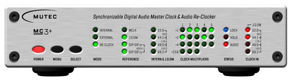
The connection is made from either an SPDIF coaxial RCA jack or a Toslink optical jack. In addition, the data stream contains the clock information, i.e. the sampling rate, e.g. 44.1kHz up to 192kHz. So far, everything is great. The huge problem is that a personal computer or laptop is super noisy, which is evidenced by playing an AM radio near a PC. Besides RFI, PCs spill a lot of switching noise, which makes sense as their power supplies draw hundreds of watts. Moreover, PCs give rise to jitter, i.e. the unfortunate variation in clock synchronization. The Mutec MC3+ cleans up the noise and cascading MC3+ will further clean up the noise (at least that is what I have heard). In addition, the MC3+ re-clocks the output digital stream, thereby greatly reducing jitter.
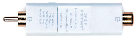
In my system, I use the Wiim WiFi streamer to receive the music my PC streams out via WiFi. The Wiim puts out either optical or RCA SPDIF. I sent the Wiim's digital output to the MC3+ via coaxial cable and then sent the M3+ output through another coaxial cable to my DAC's SPDIF input. How did it sound? Pretty amazing. Unlike magic rocks, this tweak can readily heard, as the resulting sound takes a major turn to sounding analog. In addition, fine-detail resolution improves. Is the improvement worth the $1200 price tag? It depends on the listener's budget. If your system is sporting $1200 power cords, then do not hesitate to buy one… I wondered, on the other hand, if a cheaper alternative could be had. I knew that iFi-Audio has the reputation for making low-jitter DACs, so I searched their website and found the Ifi iPurerfier2. (BTW, the 2 at the end is important, as it marks a big upgrade over the original.)
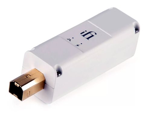
The ifi iPurerfier2 cost $199 and comes in a handsome box with lots of accessories and includes a regulated power supply (wallwart). It, too, re-clocks the digital data stream and filters away noise. I compared the two units separately and in cascade. Cascading the M3+ to the iPurerfier2 didn't improve the sound over a single re-clocker; in fact, it seemed to diminish the sound slightly, which surprised me. The best sound in my system came from using the RCA SPDIF output from the Wiim Pro Plus to the iPurerfier2 and, then, taking its optical SPDIF output to the Pro-Ject DAC Pre Box S2 run off of a battery. Amazingly solid imaging. No tonal differences, other than better defined deep bass. In general, a more relaxed and effortless sound. On the other hand, I get more fine-detail resolution from my Schiit Gungnir revision-B multibit DAC, along with an analog-like sound. The first thing I noticed was that the sound level seemed lower with both the M3+ and the iPurerfier2. That is not possible. The digital code remains constant, with no truncating of the ones and zeros. So why the odd result? Our ears evaluate SPL differently from an SPL meter, as the ear has learned to correlate high distortion with high SPL. For example, a car drives by with blaring music playing inside, and our ears hurt. Yet, the SPL might be relatively modest on the SPL meter, say 85dB, but the THD might be 30%. Unlike our eyes, which readily handle near infinite distortion without distress, our ears hurt when hearing 30% distortion. In other words, the re-clocking and cleaning up of the digital stream produces less distortion, which our ears evaluate as lower volume. The less distortion does not take the form of harmonic distortion, but timing and glitching distortion, which both the M3+ and the iPurerfier2 eliminate. On the other hand, if you are lucky enough to own an already perfect digital audio system, these two devices will not add anything, as you cannot improve upon perfection. Stupidly, I never tried the reverse: running the Wiim's output into the iPurerfier2 to the Mutec with is optical output. So what is my take on the iPurerfier2? The best $200 I have ever spent. I love that the electrical connection to my PC is broken by WiFi signal and that the data leaving the iPurerfier2 travels through optical cable, thereby breaking that electrical connection. (I believe that in my system, that the Mutec M3+ didn't deliver its true potential due to it using a three-prong AC wall plug, which introduced house-ground problems, problems that the two-pronged regulated wallwart power supply from iFi avoided. Once again, I wish I had experimented with the M3+ optical output.) BTW, iFi makes an USB purifier: the iPurerfier3, which has USB input and output, along with optical SPDIF output.
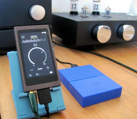
It, too, re-clocks and filters. In addition, it regenerates the digital output signal and rebalances it, eliminating DC offset. Amazingly, it costs $70 less than it brother iPurerfier2 (it doesn't need an external power supply, as the USB supplies the needed power). I almost bought one just to use with my laptop. Often, I hook up my Sony NW A45 personal music player as an external DAC and headphone amplifier; the connection is made through a USB cable. My guess is that the iPurerfier3 might improve the sound enough to bypass the need for additional tube sweetness.
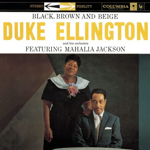
Music Recommendation: Black, Brown and Beige I searched for a more recent recording of the work, and I found Wynton Marsalis' release of the 2018 performance, with Brianna Thomas singing and the Jazz At Lincoln Center Orchestra taking the place of a jazz big band. Well worth hearing.
In my further searching, I discovered a more classically flavored version offered on the Naxos label.
This recording also holds four additional Ellington compositions. Moreover, Amazon Music and Qobuz streaming services deliver it in 24-bit, 192kHz resolution. Now we are talking—or, rather, now we are listening. I just put this album on my shortlist of must hear recent albums, as this is what audiophile dreams are made of. Naxos has to be the most under-rated classical-music label—in spite of their often excellent recordings.
//JRB
Did you enjoy my post? Do you want to see me make it to post 1,000? If so, think about supporting me at Patreon.
User Guides for GlassWare Software
For those of you who still have old computers running Windows XP (32-bit) or any other Windows 32-bit OS, I have setup the download availability of my old old standards: Tube CAD, SE Amp CAD, and Audio Gadgets. The downloads are at the GlassWare-Yahoo store and the price is only $9.95 for each program. http://glass-ware.stores.yahoo.net/adsoffromgla.html So many have asked that I had to do it. WARNING: THESE THREE PROGRAMS WILL NOT RUN UNDER VISTA 64-Bit or WINDOWS 7, 8, and 10 if the OS is not 32-bit or if it is a 64-bit OS. I do plan on remaking all of these programs into 64-bit versions, but it will be a huge ordeal, as programming requires vast chunks of noise-free time, something very rare with children running about. Ideally, I would love to come out with versions that run on iPads and Android-OS tablets.
|
I know that some readers wish to avoid Patreon, so here is a PayPal button instead. Thanks.
John Broskie
John Gives
Special Thanks to the Special 88 To all my patrons, all 88 of them, thank you all again. I want to especially thank
I am truly stunned and appreciative of their support. In addition I want to thank the following patrons:
All of your support makes a big difference. I would love to arrive at the point where creating my posts was my top priority of the day, not something that I have to steal time from other obligations to do. The more support I get, the higher up these posts move up in deserving attention.
If you have been reading my posts, you know that my lifetime goal is reaching post number one thousand. I have 397 more to go. My second goal was to gather 1,000 patrons. Well, that no longer seems possible to me, so I will shoot for a mighty 100 instead. Thus, I have just 12 patrons to go. Help me get there. Thanks.
Only $12.95 TCJ My-Stock DB
Version 2 Improvements *User definable Download for www.glass-ware.com
|
|||


| www.tubecad.com Copyright © 1999-2024 GlassWare All Rights Reserved |