| John Broskie's Guide to Tube Circuit Analysis & Design |
28 August 2024 Post Number 607
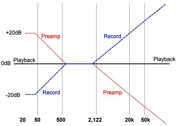
Almost Forgotten RIAA EQ Technique The actual audio signal engraved on an LP is not frequency flat: the lows are attenuated; the highs, boosted. This was done to extend playback time and to reduce surface noise. To get a flat frequency response requires that the phono preamp undoes the LP's equalization by imposing an inverted version of the LP's equalization. In other words, the phono preamp must boost lows and attenuate highs.
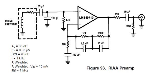
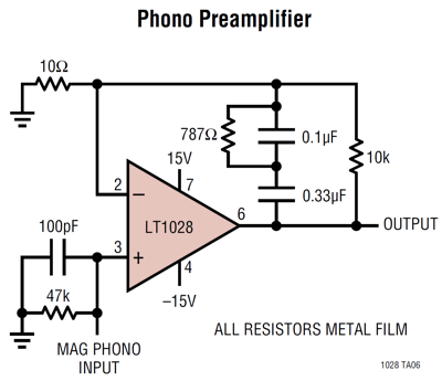
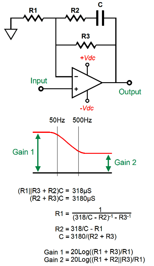
The three transition frequencies are 50Hz, 500Hz, and 2122Hz, which correspond to the three time constants of 3180µs, 318µs, and 75µs. (To translate a time constant into frequency just divide 159155 by the time constant in µs.) Although RIAA equalization can be achieved either by passive or active means, a safe pronouncement is that most phono preamps use active equalization, wherein the negative feedback loop contains added capacitors that force the inverse equalization on the output signal. Here is an example of active equalization:
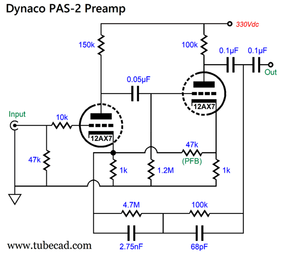
This negative feedback arrangement is quite old school, as it first appeared in tube-based phono preamps. For example, here is the Dynaco PAS-2 Preamp.
(The 47k resistor marked PFB provides positive feedback to the input triode, increasing the final gain.) While this two-resistor, two-capacitor negative feedback loop for RIAA equalization is the most popular topology, other arrangements exist.
To see how the feedback equalization works note that the amplifier's DC the gain is equal to (10 + 10k)/10 or 1:1001; but at high-frequencies its gain falls off, in a staggered manner, arriving at unity-gain at some near-infinitely high frequency. In contrast, phono stages that employ passive RIAA equalization hold two frequency-flat gain stages with a passive equalization network wedged between.
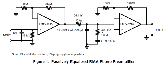
Of course, we can create a hybrid RIAA equalization that uses both active and passive equalization. My preference is to actively equalize the bass frequencies from 50Hz to 500Hz, but use a passive low-pass filter at 2122Hz. Why? The higher the frequency, the better passive filters work; conversely, the lower the frequency, the better active filtering works (or at the very least, gets away with lower-valued capacitors). Remember LPs present much more high-frequency content than just the music, as ticks and pops and scratches produce high-frequency bursts of signal. Here is one such example from post 494.
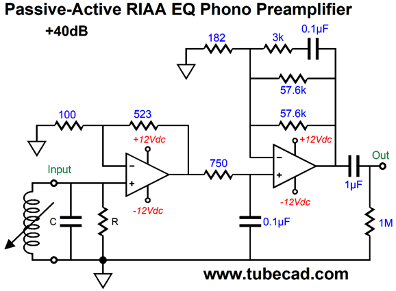
The input OpAmp delivers a flat-frequency response, but once its output signal passes through the 750-ohm resistor and is shunted by the 0.1µF capacitor, the 2122Hz low-pass filter function is complete, leaving only the bass boost from 50Hz to 500Hz for the second OpAmp. The second OpAmp performs this equalization actively through its negative feedback loop. (The two 57.6k resistors are there as they do not make a 28.8k resistor.) From post 535, we see an all-active RIAA equalization arrangement.
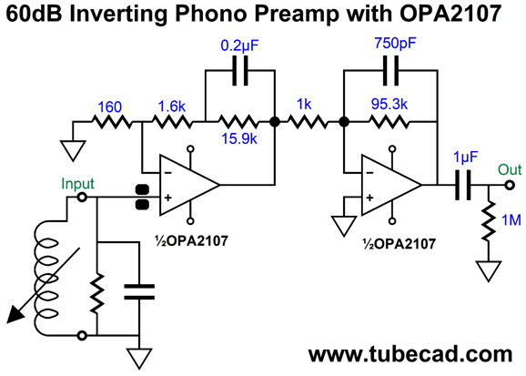
This time, the first stage performs the bass boost, while the second stage accomplishes the 2122Hz low-pass filter. The math behind active equalization in the prior circuit was given in post 494.
Now, we can arrive at the interesting active RIAA equalization technique. Let's start by imagining that resistor R3 is removed from the circuit shown above. What is the DC gain? Without R3, the DC gain equals the OpAmp's open-loop gain. Solid-state OpAmps offer screaming high open-loop gain; for example, the low-noise AD797 OpAmp offers an open-loop gain of 1:20Meg, yes 20 million (146dB). At high-frequencies, the gain equals (R1 + R2)/R1. If R1 equals 100 and R2 equals 10k, then the gain at high-frequencies equals 1:101 (or roughly +40dB). Well, the OpAmp's huge surplus of gain will help it better achieve flat inverse RIAA equalization—but tubes are a different story.
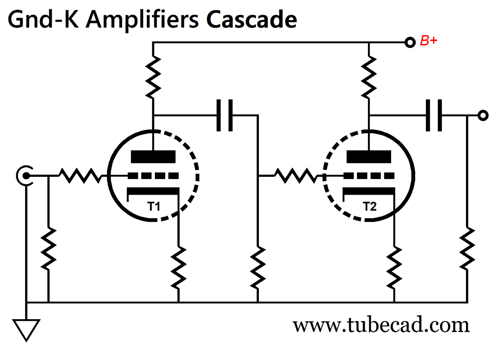
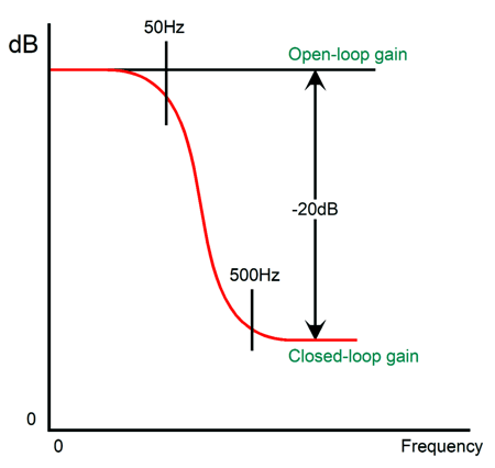
Here we see two cascaded grounded-cathode amplifiers, whose final AC voltage gain equals the two stage gains multiplied against each other. For example, if each amplifier stage delivers a gain of 1:20, the final gain will be 1:400 (in dB, 52dB). The RIAA equalization's bass boost from 50Hz to 500Hz results in bass boost of 20dB or 10X. If we divide 400 by 10 we get 40. In other words, if we imposed the first half the equalization curve, the final gain would equal 1:40 or +32dB. How would we do so?
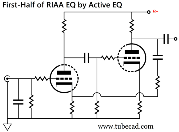
By carefully selecting the added resistor and capacitor values, we can force frequencies below 50Hz to run full out at a gain of 1:400, as the frequency reaches 50Hz, the boost falls off at -6dB per octave, -20dB per decade, so that at 500Hz, the curve flattens to 1:40. What makes this approach interesting is that it attempts to retain as much triode gain as possible, but at the cost of providing no negative feedback at frequencies below 50Hz. If we want to apply negative feedback to those very low frequencies, it will be at the expense of the final gain, as negative feedback is fueled by excess gain. The first time I saw this interesting equalization twist was in a Japanese audio magazine back in the 1980s, but I am sure it must have been developed much earlier. Here is a design example:
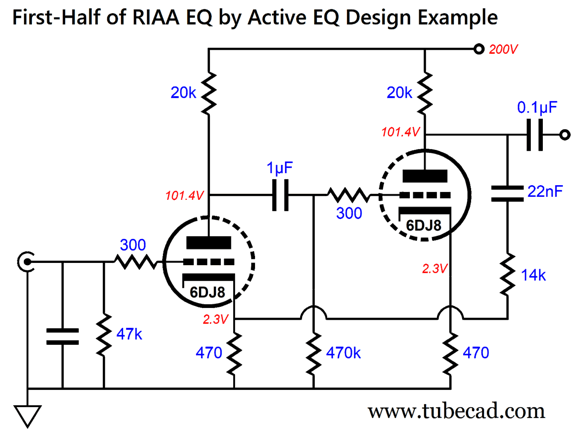
How did I come up with these values? The 20k plate resistor and 470-ohm cathode resistors were from memory. The 14k negative feedback resistor's value was from quick math—and then SPICE testing.
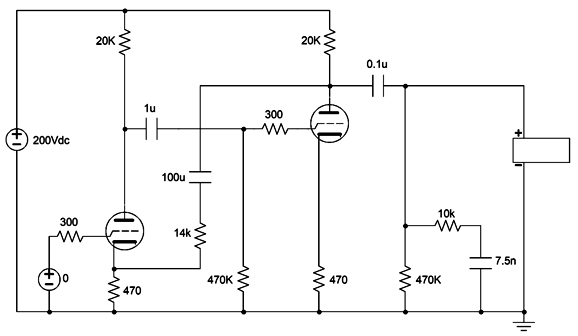
I reasoned that since the 6DJ8-based grounded-cathode amplifier split the B+ voltage at its plate, it would yield half its mu as the grounded-cathode amplifier gain, i.e. about 15. With two such stages in cascade, the final open-loop gain would equal 15 ² or 1:225. I then divided by 10, as that was the required bass boost, leaving 1:22.5 as the target gain. Next, I multiplied 22.5 against 470 (the cathode resistor value) and got 10575. Wait a minute, that's not 14k. That's right; it was only my first educated guess. I then fired up my SPICE program and used the following circuit to hone in on the precise values. Having the roughly correct part values in mind before beginning a SPICE simulation will save you a lot of time, especially with RIAA equalization. I knew that I wanted this circuit to drive a passive 2122Hz low pass filter, so I added it to the circuit. I knew that the negative feedback capacitor would impose a 500Hz transition frequency, but I didn't know that 14k would end up being the desired resistor value, so I used a ridiculously high 100µF capacitor, as I needed to find the resistor value first.
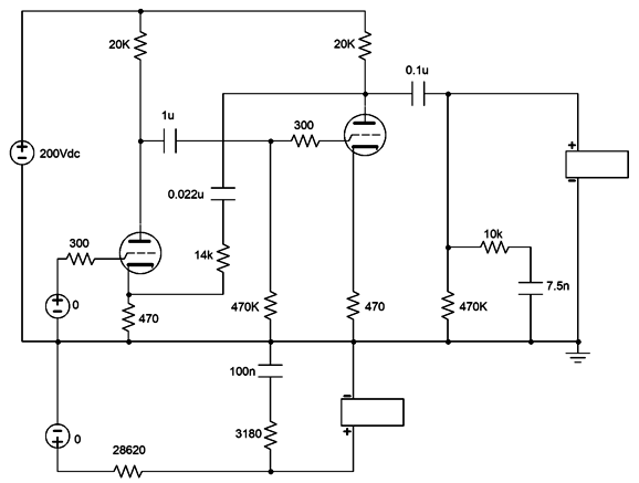
I fiddled with the feedback resistor's value until I got the closed-loop gain reduced by 1/10 or -20dB. I then added 470 to 14k and found the feedback capacitor value with the following formula: C = 159155/R/500 where R equaled 14470. The answer was 0.0219979, with 0.022 being dang close. My next step was to use the following circuit in SPICE to confirm my calculations.
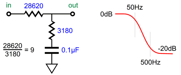
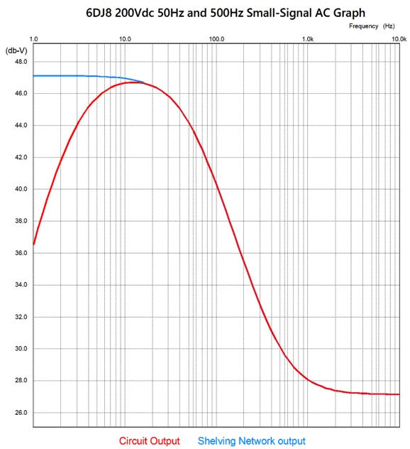
The 14k resistor and 0.022µF (22nF) capacitor are there. The two resistors and single capacitor below ground define a shelving network whose output yields the 50Hz to 500Hz first half of the RIAA equalization. In other words, this was my gold-standard reference. How well did it work?
The shelving network freely passes DC and low frequencies, but at 50Hz it begins to attenuate and then flattens out above 500Hz.
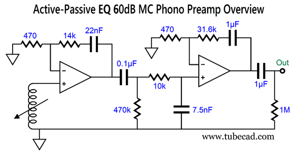
An amazing overlap this is. The departure below 20Hz due to all the coupling capacitors is not a liability, but a feature, as we do not want to amplify LP warps and turntable rumble. In fact, the equalization curve was later amended in Europe to include a 10,000µs (10ms) time constant to impose a high-pass filter at 16Hz. By the way, the AC signal source that drives the bottom passive shelving network must present a signal equal in magnitude to what the open-loop tube-based circuit delivers; in this example, 1:227 or +47.1dB. Let's complete the phono preamp by adding a second negative-feedback-based gain stage. Here is the overview of what is needed.
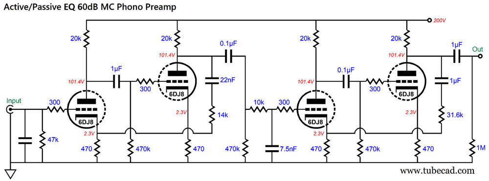
The second stage also holds a negative feedback loop, but without any RIAA equalization, as the signal entering the second stage has already been made flat by the first stage's feedback equalization and by passing through the 10k and 7.5nF low-pass filter. Now, let's do it with tubes.
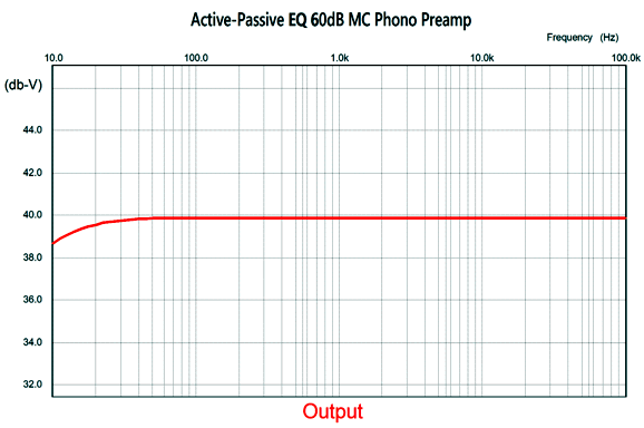
By the way, the coupling capacitor values might appear arbitrary; they're not. This is a high-gain phono preamp for use with a low-output moving-coil (MC) phono cartridge. I quite like the tube count, just two tubes per channel. Mind you, this was a design example to show how this different RIAA equalization scheme could be put to use, not as an example of how to create the ultimate tube-based phono preamp. Okay, having said that, how well did this design work in SPICE simulations? Not bad.
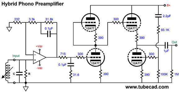
The output is flat from 20Hz to 20kHz within a third of a dB. In other words, this active-passive RIAA equalization mix works well. In post 555, we see a hybrid phono preamp that uses an OpAmp for the first stage and which include the same 50Hz to 500Hz bass boost, followed by an Aikido gain stage.
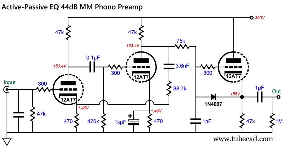
(They don't make 31.8k resistors, so we place a 16k resistor in series with 15.8k resistor.) There's a lot to like about this preamp, such as the fact that low-noise OpAmps are vastly lower in noise than the best tubes, and that the Aikido gain can easily be altered by swapping different input tubes; a 12AU7 for low gain, 12AT7 and 5751 for medium gain, and a 12AX7 for high gain. Also note the single coupling capacitor and only two tubes per channel. Okay, returning to the interesting equalization technique, if the triodes used provide enough gain, we use just three triodes to make an MM phono preamp.
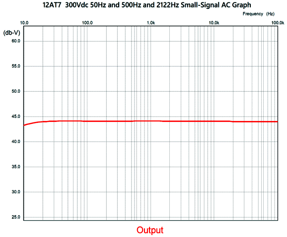
The cascade of two 12AT7-based grounded-cathode amplifiers yields an open-loop gain of 64dB. Subtracting 20dB for the required bass boost, we get a final gain of 44dB. In SPICE simulations, the results were quite promising for such a simple circuit.
The output is flat from 20Hz to 20kHz within 0.2dB, which is amazing considering that all the part values are standard 1% resistor and 5% capacitor values.
In Pursuit of Musical Digital Even I wondered if it was true. It was time to return to actual analog. I listened to LPs for about half the day, digging out old favorites, my ears swimming in an analog lake of sound. I have recently rediscovered my love of Duke Ellington's music, so the first album I dug out was his The Afro-Eurasian Eclipse.
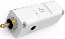
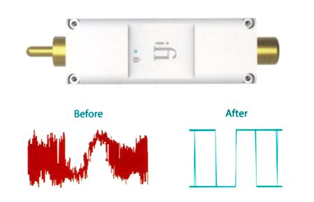
All things considered, LPs are amazing. Albums I haven't played for a quarter of century sound so familiar, so compelling. (Mind you, if I didn't already own 22 linear-feet of LPS, I wouldn't think of starting an LP collection.) I gave my ears a half hour rest, and then I listened to the digital versions of the same albums. Interestingly enough, often the LP's sonic stage was wider—but often in a gimmicky, forced way. (When stereo first arrived in HiFi, listeners wanted to hear separation, good and hard; so recording engineers gave it to them good and hard. But when old albums were remastered for CD production, the extreme stereo effect was tamed.) Returning to streamed re-clocked digital did not prove disappointing, as that same liquid flow of music had been retained. Missing was the LP surface noise and ticks and pops. I did run into a sonic snag, however, as I could not consistently stream 192kHz with the Mutec M3+ in the system—well, at least not when using the Toslink fiber cables. I remove the M3+ and used the Wiim Pro Plus WiFi streamer's optical output to the iFi SPDIF iPurifier2 and its optical out to my DAC. This not only played 192Khz music files flawlessly, it sounded just as good as having the M3+ in cascade. I still want to experiment with cascading re-clockers, so I ordered another iFi SPDIF iPurifier2, which I will then cascade optically with my existing unit. If there's anything to cascading re-clockers, that setup should reveal it.
By the way, the highly-rated Aqua DAC from Italy uses separate power supplies for each of its stages and only connects the digital signal from stage to stage via optical cable. Hence, no ground issues, no power-supply noise recirculation. As John Milton put it,
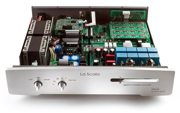
Back in 1637, "trip" also meant to dance, so we soon got "trip the light fantastic." Stop and think about it: isolating two stages with fiber optic beats isolation transformers, as the capacitance between primary and secondary define a coupling capacitor of sorts, which helps explain their seemingly too good high-frequency response. By the way, Aqua also makes a deluxe DAC, the La Scala MKII Optologic DAC, which includes tube-based output stages.
Well, I got the optical linked re-clocker and de-jitter along with a DAC hold holds four super-linear medical-instrumentation DAC ICs and my tube-based unity-gain buffers.
I love the results I am getting. Is there anything not to like? I can only think of one thing. Let's start with one of my signature crazy analogies. I was once asked what I thought of the bottle of whisky I had bought recently. I stated that it was good, very good, but dangerous. How so? The whisky was quaffable—a dangerous attribute for a strong liquor, as one risks drunkenness due to the ease with which it went down one's throat. Well, re-clocking and de-jittering makes for a far more quaffable sound, so much so that we risk playing at far higher volume than our ears should be subjected to. As I stated in my last post, "our ears evaluate SPL differently from an SPL meter, as the ear has learned to correlate high distortion with high SPL." Remove the distortion and we remove the curbs and discouragements to higher SPL.
UPDATE By the way, I measured the resistance between the Mutek M3+ connection to the house ground to signal ground. Zero, there was no resistance, which I believe explains why I had issues with it, as I have endeavored to prevent this from happening with my House-Gnd circuits.
Music Recommendation: Arooj Aftab's Night Reign Ms. Aftab is a Pakistani-American singer, composer, and producer, so Wikipedia informs us. She sings jazz, world, pop-adjacent—all of it in a minimalist and enchanting fashion. Her latest album, Night Reign, is a great place to start listening. Start with the third track, "Autumn Leaves," and then let the fourth track, "Bolo Na," follow. Amazon Music and Qobuz both offer this album in 24-bit, 96Hz resolution.
//JRB
Did you enjoy my post? Do you want to see me make it to post 1,000? If so, think about supporting me at Patreon.
User Guides for GlassWare Software
For those of you who still have old computers running Windows XP (32-bit) or any other Windows 32-bit OS, I have setup the download availability of my old old standards: Tube CAD, SE Amp CAD, and Audio Gadgets. The downloads are at the GlassWare-Yahoo store and the price is only $9.95 for each program. http://glass-ware.stores.yahoo.net/adsoffromgla.html So many have asked that I had to do it. WARNING: THESE THREE PROGRAMS WILL NOT RUN UNDER VISTA 64-Bit or WINDOWS 7, 8, and 10 if the OS is not 32-bit or if it is a 64-bit OS. I do plan on remaking all of these programs into 64-bit versions, but it will be a huge ordeal, as programming requires vast chunks of noise-free time, something very rare with children running about. Ideally, I would love to come out with versions that run on iPads and Android-OS tablets.
|
I know that some readers wish to avoid Patreon, so here is a PayPal button instead. Thanks.
John Broskie
John Gives
Special Thanks to the Special 85 To all my patrons, all 85 of them, thank you all again. I want to especially thank
I am truly stunned and appreciative of their support. In addition I want to thank the following patrons:
All of your support makes a big difference. I would love to arrive at the point where creating my posts was my top priority of the day, not something that I have to steal time from other obligations to do. The more support I get, the higher up these posts move up in deserving attention.
If you have been reading my posts, you know that my lifetime goal is reaching post number one thousand. I have 393 more to go. My second goal was to gather 1,000 patrons. Well, that no longer seems possible to me, so I will shoot for a mighty 100 instead. Thus, I have just 15 patrons to go. Help me get there. Thanks.
Only $9.95
The Tube CAD Journal's first companion program, TCJ Filter Design lets you design a filter or crossover (passive, OpAmp or tube) without having to check out thick textbooks from the library and without having to breakout the scientific calculator. This program's goal is to provide a quick and easy display not only of the frequency response, but also of the resistor and capacitor values for a passive and active filters and crossovers. TCJ Filter Design is easy to use, but not lightweight, holding over 60 different filter topologies and up to four filter alignments: While the program's main concern is active filters, solid-state and tube, it also does passive filters. In fact, it can be used to calculate passive crossovers for use with speakers by entering 8 ohms as the terminating resistance. Click on the image below to see the full screen capture.
Tube crossovers are a major part of this program; both buffered and un-buffered tube based filters along with mono-polar and bipolar power supply topologies are covered. Available on a CD-ROM and a downloadable version (4 Megabytes). |
|||


| www.tubecad.com Copyright © 1999-2024 GlassWare All Rights Reserved |