| John Broskie's Guide to Tube Circuit Analysis & Design |
| April 20 2025 | Post Number 619 |
||||
Balanced Input for Single-Ended Amplifiers
Since single-ended power amplifiers do not push and pull, no phase splitter is needed. Does this mean that a balanced input signal cannot be used with a single-ended amplifier? No. If nothing else, the single-ended power amplifier could just ignore one of the pair's balanced signals.
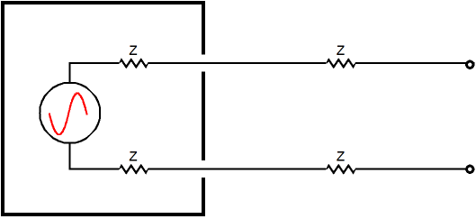
Such a setup is possible because we do not produce "true" balanced signals today, as true balanced uses only two connections, not three. Today, a third connection (Pin 1) is included, i.e. the ground connection. Originally, this ground connection was only meant to be used to connect to the cable's outer shield, as an unterminated shield can act as an antenna, which can be undone by terminating the shield into small-valued capacitor (often in series with a 51-ohm resistor) to the receiving circuit's chassis. In other words, with a true balanced input signal, we cannot just ignore one connection pin.
To help make this point more clear, imagine that the true-balanced input signal comes from a signal transformer's secondary. Attaching to just one end of this winding will only produce a lot of hum, no music. Of course, we could add a two-resistor voltage divider and a ground connection, as this would allow us to take signal from only one end of the secondary, but we could just as easily forgo the two resistors and just ground the other end. 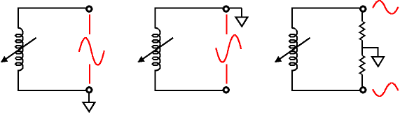
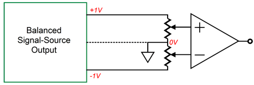
If the balanced-signal source does not hold an output transformer with a floating secondary (in other words, if it grounds a center-tap on the secondary), we cannot just ground the inverting pin, as the common connection to the house ground will cause a shorting. House grounds promote safety, sadly, not audio excellence. A more interesting use of a set balanced input signals would be for the single-ended amplifier to utilize the pair of non-inverted and inverted signals to further the aims of the amplifier. For example, most DAC's that sport XLR output jacks deliver at least ±2Vpk of output signal, which sums to 4Vpk of unbalanced signal, which is a lot of signal, considering that most power amplifiers can be driven to full output with only 1Vpk of input signal. In other words, the single-ended power amplifier could get away with one fewer gain stages with such a hot input signal. (Many high-end DACs come with remote controls that allow volume control, thereby eliminating the need for a line-stage amplifier or preamp.) Here is an example amplifier that uses an input transformer:
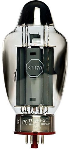
If it were not for the expense, input transformers would be much more popular, as they solve many ground-loop headaches. In addition, they guard against DC offsets and RFI contamination in the input signal, due to the transformer limited bandwidth at both extremes. In this example, a power pentode, such as the KT88, KT120, KT150, and KT170, is triode-connected. Speaking of the KT170, the new big beast on the block, here it is.
With its high plate dissipation limit of 85W and its arresting appearance, this power tube would make a fun single-ended power amplifier output tube. Okay, returning to the single-ended amplifier schematic, the output tube requires around 30Vpk to 40Vpk of input signal to be driven to full output. The 6SN7-based input grounded-cathode amplifier only delivers a gain of 1:10 (+20dB), but with the 4Vpk of input signal coming out of the transformer's secondary, we have enough to drive the output tube. The cathode follower makes use of the other triode in the 6SN7's envelope; in addition, it can drive the output tube into positive-grid current with little ill effect. The DC servo auto biases the output tube. For example, if we give the output tube a 10-ohm cathode resistor and set the servo's reference voltage to +1Vdc, the output tube will auto bias to 100mA, as 1/10 equals 0.1. The OpAmp must be a high-voltage type. (See Post 591 for more details on DC servos.) With the input transformer, we can get extra fancy and include some Aikido Mojo, as was revealed in Post 486.
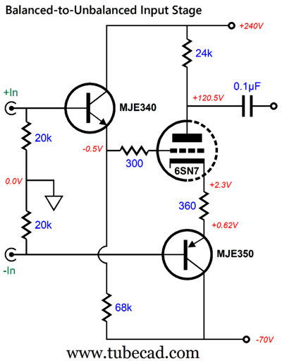
The input potentiometer is not necessary and can be replaced by simply a transformer-load resistor. Resistors R1 and R2 along with the unmarked capacitor inject a sampling of the power-supply noise into the grounded-cathode amplifier's grid, thereby forcing a power-supply-noise null at its output. The resistor values depend on the triode's amplification factor (mu). The input transformer makes this trick possible. Of course, some do not like input transformers or are unwilling to shell out the $100 to buy one. A $2 alternative that also sums the two balanced input signals is the following:
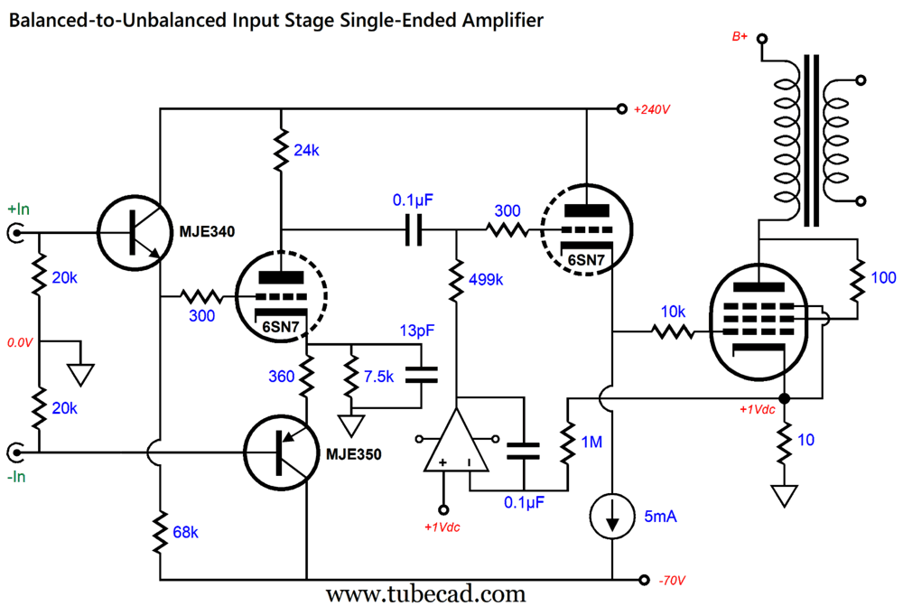
The two transistors are configured as emitter followers, which deliver no signal gain but do buffer the input signals. In other words, the triode is driven at both its grid and cathode in anti-phase, so the triode experiences the full 4Vpk of signal from the DAC with balanced outputs. Note the base-to-emitter voltage drops and how they combine to create a 1.12Vdc voltage differential, which explains why the lower-resistance cathode resistor value (360 ohms) is used compared to that of the previous design example (560 ohms). We have gotten our desired gain, but we lost the input transformer's excellent common-mode rejection ratio (CMRR), which eliminated common-mode signals, such as external electrical noise, from being passed on and amplified. In fact, the CMRR for this circuit is only -5dB. Pitifully weak. Of course, I have a sneaky solution:
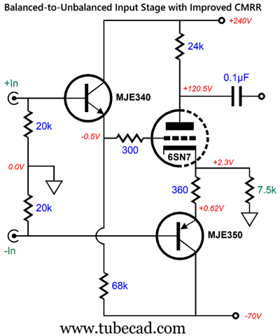
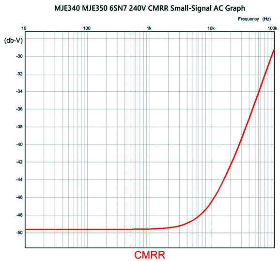
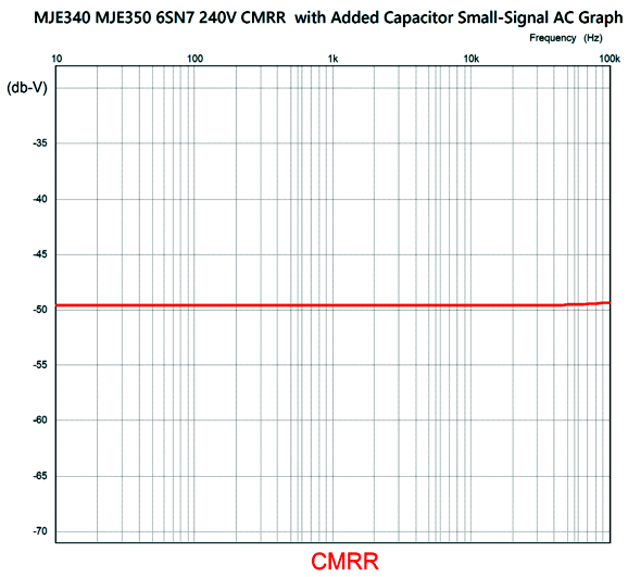
Ah, the magical benefits of one additional and well-placed resistor are breathtaking to behold. (By the way, "sneaky" is the polite and humble way to say effing brilliant.) The added 7.5k resistor delivers a CMRR of -49.6dB at 100Hz, as it has rebalanced the signals.
If we shunt the 7.5k resistor with a 13pF capacitor, we extend the CMRR farther up the bandwidth.
Simple solutions are the best solutions. Let's make a single-ended power amplifier based on this input stage.
What about adding some Aikido Mojo to improve the PSRR? I know how and can do it, but it would only work when the input signal source was connected and when that signal source provided a low input output impedance. I, therefore, leave it for the enterprising reader to figure out on his/her own. A two-tube mono power amplifier would be fun to look at, especially if it held octal tubes. No doubt, some readers are thinking, "Are you crazy? Why would I tolerate any transistors in my SINGLE-ENDED power amplifier?" Well, we could use the following circuit to sidestep the transistors.
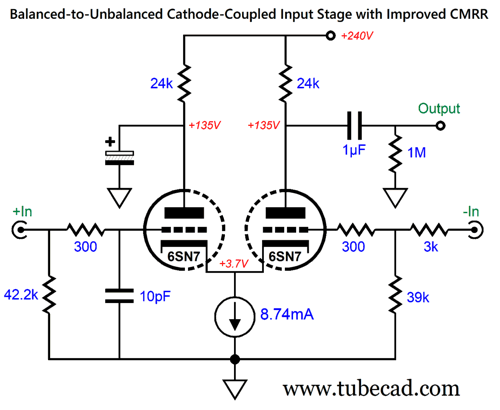
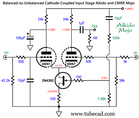
The typical Cathode-Coupled amplifier grounds the right triode's grid. Here, instead, we drive it with the inverted input signal from the XLR jack. The result is that we get roughly twice the gain from the circuit. Once again, this textbook circuit delivers a poor CMRR, only a little better than -1dB. Why so little? The non-inverted input signal gets attenuated by the left triode's—which acts as a cathode follower—insertion loss. Thus, the right triode does not see equal input signals. My workaround is the following:
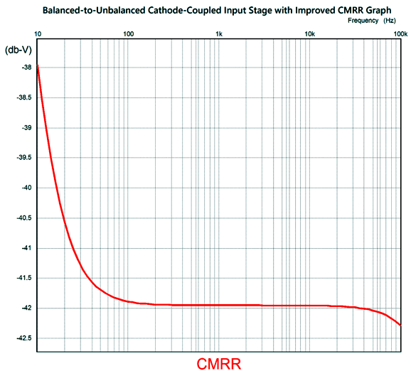
The added 10pF capacitor and 3k resistor create a -40dB greater improvement in CMRR.
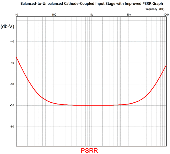
The capacitor that shunts the let triode's plate to ground was a 150µF capacitor in my SPICE simulations. The larger the capacitor's value, the further the CMRR extends down in frequency. And once again, we got improved CMRR but not PSRR. In fact, the Cathode-Coupled amplifier with a constant-current source cathode loading delivers almost no PSRR. My workaround is to modulate the constant-current source by feeding's gate a portion of power-supply noise, which prompts it to deviate from constant-current conduction to modulated anti-phase conduction.
FETs intrinsically make great constant-current sources, unlike triodes and transistors. Here is the SPICE-produced graph:
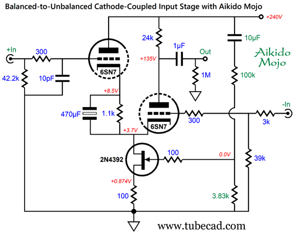
A variation on the Cathode-Coupled amplifier topology adds a cathode resistor and removes a plate resistor.
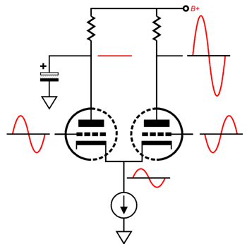
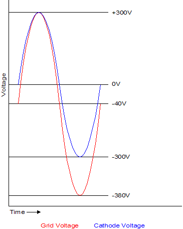
Since the left triode's plate voltage has jumped up to 240Vdc, its cathode voltage must be raised as well to maintain the same idle current flow. This arrangement allows us to use a small low-voltage non-polarized electrolytic capacitor in place of the large high-voltage polarized electrolytic capacitor. (If a 4.8V zener can be found, it could replace the 1.k cathode resistor.) The more I think about using the cathode-coupled topology, the more I find it lacking in potential gain. If we probe the voltage swings within its operation, we see that the connected cathodes swings follow that of the left triode's input signal, but in an attenuated fashion.
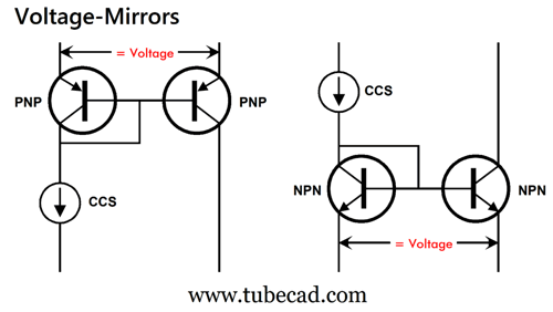
If the left triode, which functions as a cathode follower, delivered true unity-gain, we would get more gain from the right triode, as it would see a greater differential input signal. How can we augment the cathode follower action, bringing its gain closer to unity-gain? Well, we will need a new circuit concept: the voltage mirror. We all know what a current mirror is, but this topology does not mirror current; instead, it mirrors voltage.
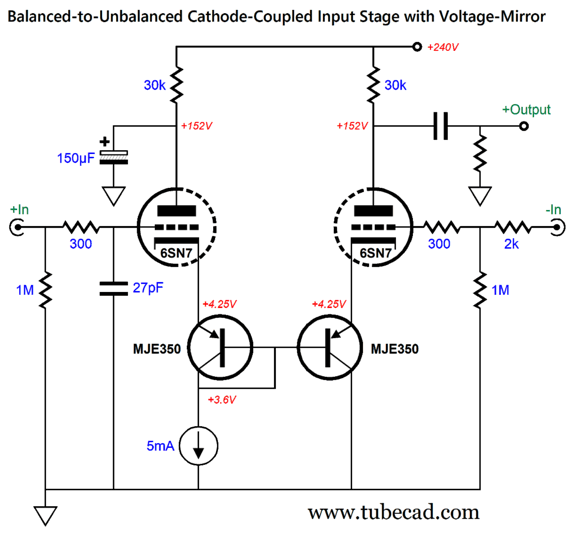
Let's plug the PNP-transistor version into a cathode-couple amplifier to see how it works:
The left triode is barely loaded at its cathode, as the constant-current source and base current draw is trivial, so it delivers a closer approximation to true unity-gain. The right MJE350 PNP transistor functions as an emitter follower, which then drive the right triode's cathode. The result is higher gain. How much more? The conventional cathode-coupled amplifier with my CMRR and PSRR enhancements produces a gain of 23 with ±1Vpk of balanced input signal. The version with the voltage-mirror delivers a gain of 32. Some of the extra gain is due to the 30k plate resistors, but not that much. Why is more gain important? The balanced signal source may not put that much output and we can use lower-transconductance output tubes, such as the 300B. In sum, we see that using a balanced input signals to drive a single-ended power amplifier is not just seemingly perverse, it's smart.
Single-Ended Cathode-Follower OPS
In other words, we must pay for the huge advantages provided by the cathode follower output stage with a huge drive signal.
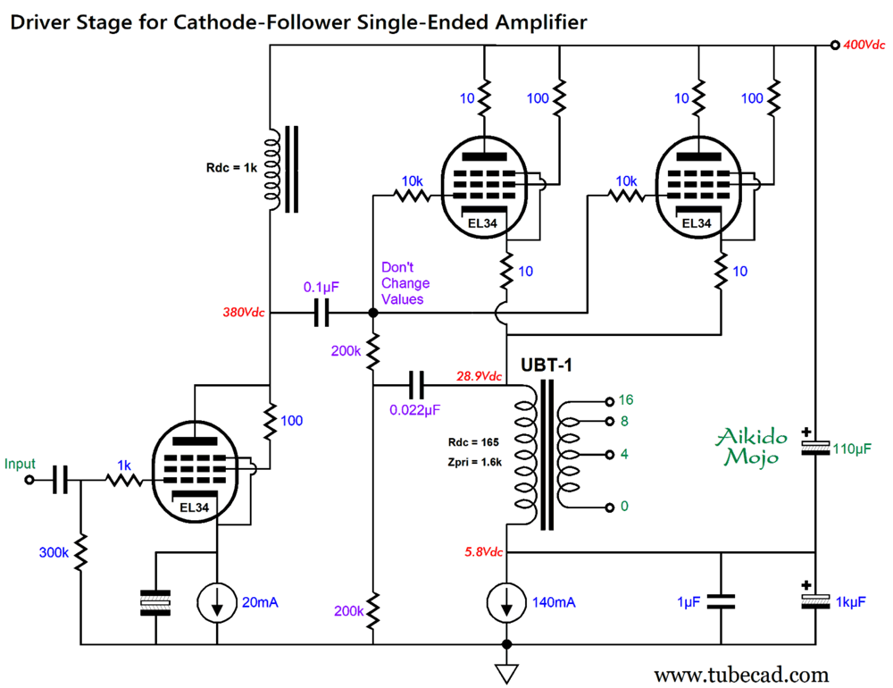
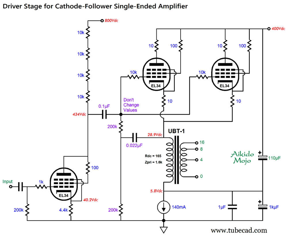
In addition to the problem of having to deliver a huge drive signal, we have the problem a relatively poor PSRR from the cathode-follower output stage, with the lower the output triode's amplification factor (mu), the worse the PSRR. My workaround is to add some Aikido Mojo:
A triode-connected EL34, with a cathode-to-plate voltage of 370V and an idle current flow of 70mA, exhibits a mu of about 9.1, which if we divide into the 1kµF capacitance that shunts the constant-current source, yields a capacitance value roughly equal to 110µF. This arrangement delivers 1/(mu + 1) of the power-supply noise to the bottom of the output transformer's primary, which results in big improvement in PSRR. The inductor-loaded EL34 allows for huge output voltage swings from this robust driver tube. (In addition, a monobloc power amplifier that held three EL34 tubes would look very cool indeed.) The part values in purple should not be changed, as you can end up with an unintended bass boost. (Of course, some might welcome the boost, probably also falsely attributing the great bass to the capacitor brand.) Alas, finding high-quality load inductors is not easy, as power-supply inductors won't cut it. We cannot simply replace the inductor with a plate resistor, as we will never get as large output voltage swings, due to the voltage drop across the plate resistor. The workaround is to use an additional 800Vdc power-supply rail voltage for the driver stage:
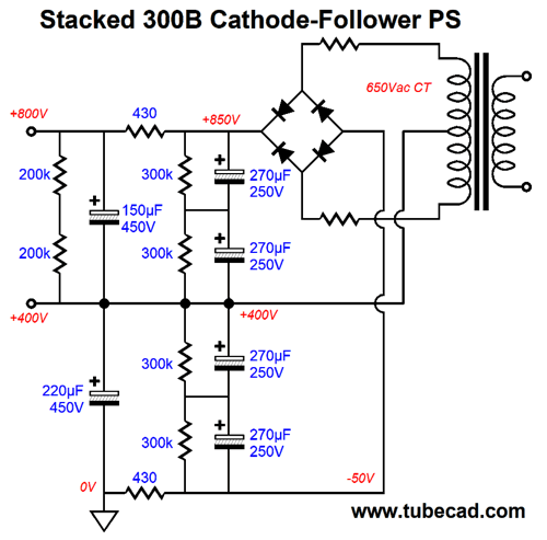
Getting a secondary high-voltage power-supply rail is not too difficult, if we use a center-tapped high-voltage secondary. From Post 505:
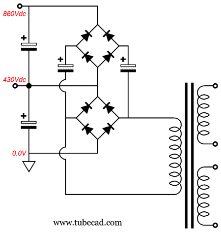
If the high-voltage secondary does not hold a center-tap, then we could use the following topology to create the additional high-voltage power-supply rail.
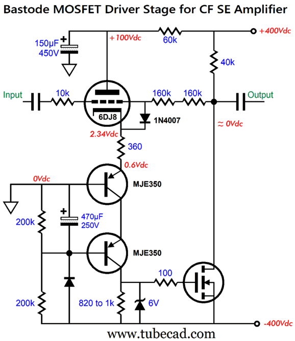
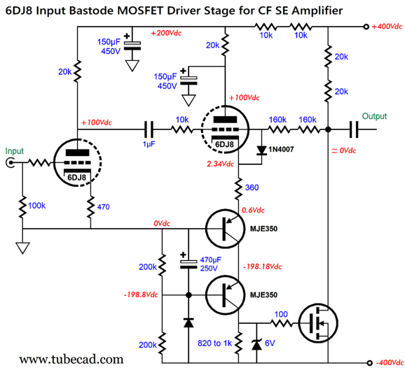
The secondary bridge rectifier and two power-supply capacitors create the new high-voltage rail voltage. Note the excessive voltage. The assumption here is that each power-supply rail will see an RC filter to strip away the ripple and lower the voltages. A further assumption is that since the driver stage's wee 20mA idle current, one seventh that of the output stage, the 800Vdc rail voltage should prove very much noise-free. An alternative driver circuit makes use of the new low-capacitance, high-voltage MOSFETs:
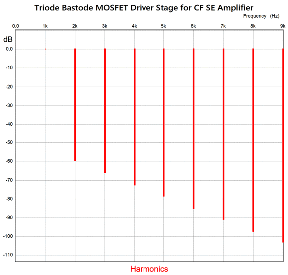
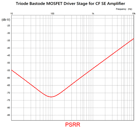
A bipolar power supply is needed, but the previous power-supply designs can be used to create one. The 6DJ8 triode forms a bastode (inverted cascode) with the top MJE350, which in turn is cascoded by the bottom MJE350 PNP transistor. The diode only engages when the 6DJ8 triode is missing from its socket or is still cold and not conducting. The 6V zener protects the MOSFET from excessive gate voltage. The 10k and the two 160k resistors define a negative feedback loop, which feedbacks both AC and DC to the triode's grid. The resistor values imply a gain of 1 to 32, but in SPICE simulations I got 1 to 31.86, which is plenty close. Here is the SPICE-generated Fourier graph with a 1kHz sinewave at ±318.6Vpk:
The THD roughly translates to 0.1%. More importantly, note the lovely single-ended cascade of harmonics. The PSRR came in at -72dB at 100Hz.
The 6DJ8's twin can be used as the input tube, which need only deliver a gain of around 1:10 (+20dB).
Note the resistors in series. With this high-voltage bipolar power supply, a single MOSFET's drain 40k resistor could possibly see a near 800V voltage drop. If we do the math, we find that 800²/40k = 16W. Yes, this is the worst-case scenario, for at idle and under normal use the dissipation is only 4W. I would, nonetheless, over-build and use four 10k/3W resistors in series. In sum, this hybrid driver stage looks super promising.
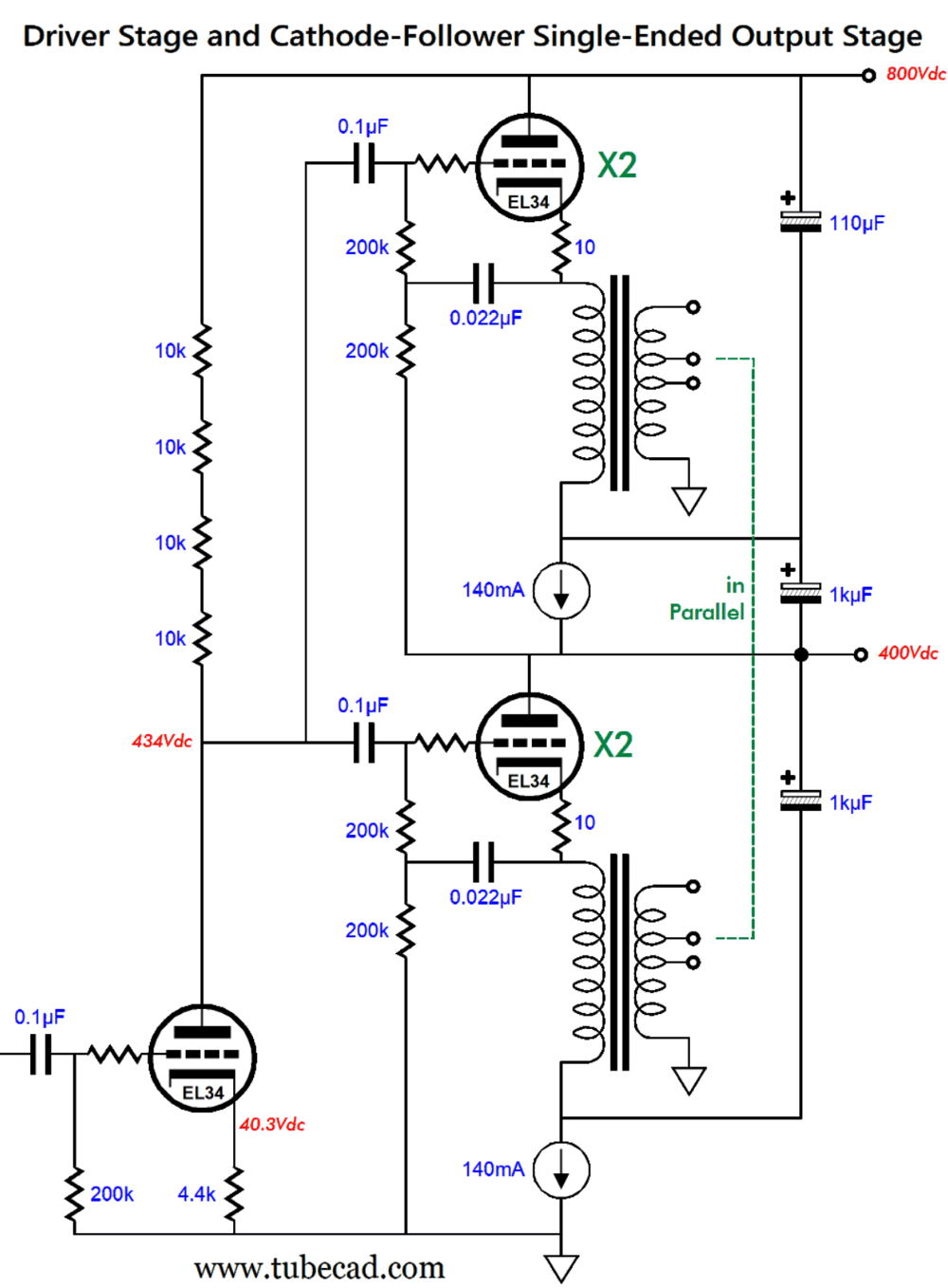
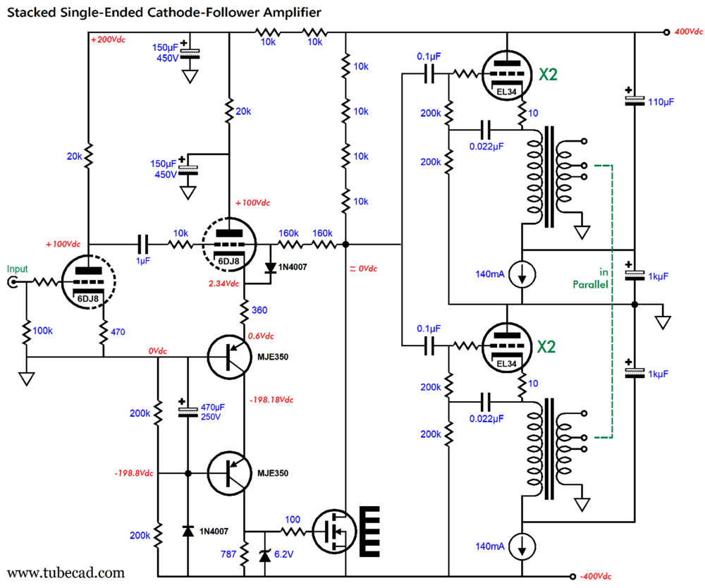
Stacked Cathode-Follower OPS Revisited
The EL34-based driver stage splits the ripple at that 800V power-supply rail, which means that its output will match exactly the amount of ripple present on the 400V power-supply rail. The top output stage then uses my two-capacitor Aikido-Mojo technique to cancel the ripple at the top output tubes' plates. The bottom output stage is effectively signal-referenced to the 400V power-supply rail, so this output stage sees virtually no ripple, as the constant-current source that auto-bias the bottom EL34 output tube also shields these tubes from the ground. Yes, paradoxically enough, this creates a better PSRR. Let me put it differently, the bottom output tubes see 100% of the ripple present on the 400V power-supply rail at their cathodes, grids, and plates, so effectively they are blind to the ripple. Without a difference, there's no signal. Relative to the bottom secondary, there is ripple, but as there's no fluctuation in current flowing through the primary to relay, the secondary is ripple free. The two transformer secondaries are wired up in parallel, with the 16-ohm output taps becoming the new 8-ohm taps; the 8-ohm taps, the new 4-ohm taps. The 16-ohm output tap puts out 1.414 times more voltage than the 8-ohm tap, which implies 1.414 times more current flow and 1.414² times more power into an 8-ohm load. The math works, trust me; the output tubes still see the same load-line. I love the idea of a monobloc power amplifier sporting five EL34 tubes. Of course, we could use other output tubes, but we should keep the EL34 driver tube. I have to remind everyone that since the output tubes' cathodes travel huge voltages, their heater elements must be floating and referenced to the cathodes, not ground or any fixed voltage. In other words, a separate floating heater winding for the bottom output tubes and one for the top output tubes. By the way, this stacked output-stage arrangement could be used with a high-voltage bipolar power supply; for example:
Yes, we have arrived. Imagine a monobloc single-ended power amplifier sporting four EL34 (or KT88) output tubes and two output transformers, an amplifier capable of delivering 30W of single-ended glory, with low distortion and output impedance.
Music Recommendation: Old Jazz Albums Of course, the decline has been going on since the 1940s—Wikipedia informs us, "The Jazz Age was a period from 1920 to early 1930s in which jazz music and dance styles gained worldwide popularity." By the early 1960s, it was obvious that jazz was losing its grip on ears and hearts. But now, its public decline is staggering. Yes, it thrives in university music classes, but not on the airwaves or digital streams. The one good sign is, according to Google's AI, "The resurgence of vinyl sales has been a positive trend for the jazz genre, offering a more viable revenue stream for artists."
Still, in 2018 jazz was only 1.1% of music sales; I understand that today it's 1% but holding steady. As long as there are, however, subwoofers to thump and tweeters to sizzle and audiophiles to show off their systems, jazz will live on. Paul Motain's 1972 album, Conception Vessel, delivers system-testing music. This was the debut album by Paul Motian, the American jazz drummer and percussionist. It was released by ECM, which in my view vouchsafes its musical worthiness and sonic splendor. I saw this album being praised in an English audio magazine, so I gave it a listen. Good stuff. I wish I had known about it when it came out. (I remember seeing his name on Bill Evans albums from the late 1950s, and then again on Keith Jarrett albums from the 1970s.) Do not assume that the album is overly drum heavy. Indeed, I found it to be a nice subtlety that the first track, "Georgian Bay," is more guitar-centric. The second, track, "Ch'i Energy," definitely gives the drums more of the spotlight, but not entirely. As I listened to the album, I remember an old friend who loved Frank Zappa, and I reflected how I was sure that he would love this album.
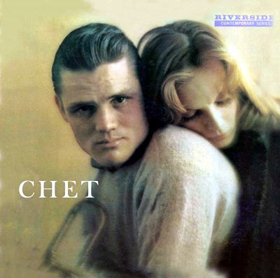
Chet Baker's 1959 album, Chet, was released in that magical year for jazz, 1959. Many know this famous jazz trumpeter for his singing, which I just don't get. This wonderful album, mercifully, is entirely instrumental. In addition, he is accompanied by other jazz greats, such as Pepper Adams, Paul Chambers, and Bill Evans. The streamed album from Amazon Music, oddly enough, delivers tracks in 192kHz and 96kHz, with one CD quality 44.1kHz. Some tracks approach audiophile grade, while others miss the mark, but the music always flows beautifully, at times in a near mournful way. I love it. //JRB
Did you enjoy my post? Do you want to see me make it to post 1,000? If so, think about supporting me at Patreon.
User Guides for GlassWare Software
For those of you who still have old computers running Windows XP (32-bit) or any other Windows 32-bit OS, I have setup the download availability of my old old standards: Tube CAD, SE Amp CAD, and Audio Gadgets. The downloads are at the GlassWare-Yahoo store and the price is only $9.95 for each program. So many have asked that I had to do it. WARNING: THESE THREE PROGRAMS WILL NOT RUN UNDER VISTA 64-Bit or WINDOWS 7, 8, and 10 if the OS is not 32-bit or if it is a 64-bit OS. I do plan on remaking all of these programs into 64-bit versions, but it will be a huge ordeal, as programming requires vast chunks of noise-free time, something very rare with children running about. Ideally, I would love to come out with versions that run on iPads and Android-OS tablets.
|
I know that some readers wish to avoid Patreon, so here is a PayPal button instead. Thanks.
John Broskie
John Gives
Special Thanks to the Special 89 To all my patrons, all 89 of them, thank you all again. I want to especially thank
I am truly stunned and appreciative of their support. In addition I want to thank the following patrons:
All of your support makes a big difference. I would love to arrive at the point where creating my posts was my top priority of the day, not something that I have to steal time from other obligations to do. The more support I get, the higher up these posts move up in deserving attention.
If you have been reading my posts, you know that my lifetime goal is reaching post number one thousand. I have 381 more to go. My second goal was to gather 1,000 patrons. Well, that no longer seems possible to me, so I will shoot for a mighty 100 instead. Thus, I have just 11 patrons to go. Help me get there. Thanks.
New URL of the GlassWare website |
||||


| www.tubecad.com Copyright © 1999-2025 GlassWare All Rights Reserved |