| John Broskie's Guide to Tube Circuit Analysis & Design |
| March 31 2025 | Post Number 618 |
|||||||||||||||||||||||||||||||||||||||||||||||||||||||||||||||||||||||||
Project Completed
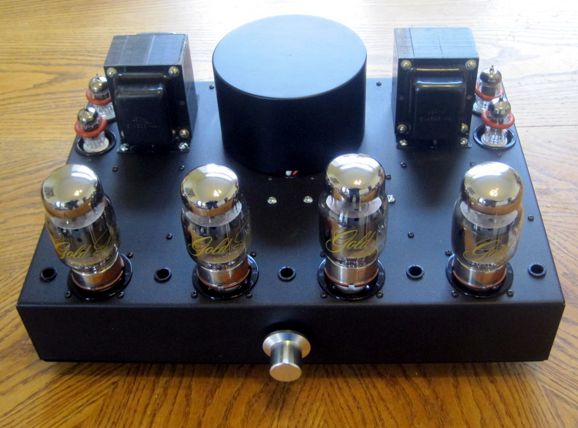
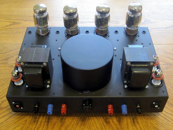
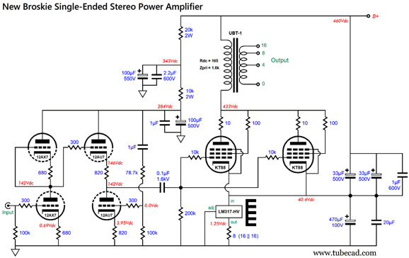
I had a goal: the desire to test if I could achieve the same level of stereo imaging with a stereo amplifier as could two mono power amplifiers. In addition, I needed to have a backup amplifier, so I could rebuild my 30-year-old single-ended amplifiers. In addition, I had a design plan, which was in many ways similar to my old mono single-ended amplifiers: Aikido input stage and parallel triode-connected output tubes with a UBT-1 output transformer, but not exactly the same. My old amplifiers used octal tubes throughout, 12SL7 and 12SN7 in the Aikido input stage and two EL34s in the output stage, while my new amplifier uses noval tubes (12AX7 and 12AU7) in the input stage and two KT88 tubes in the output stage. Fortunately, I already owned most of the needed parts, save for output tubes and power transformer.
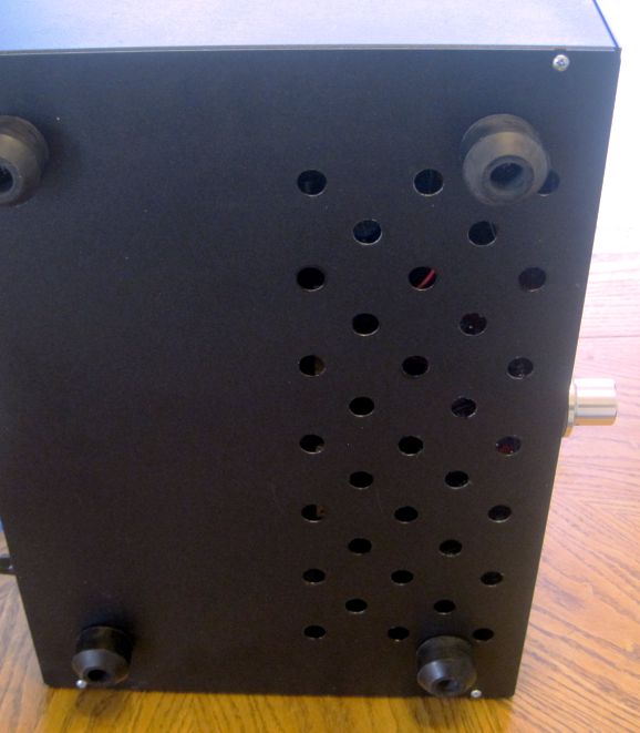
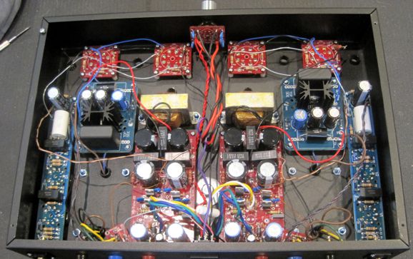
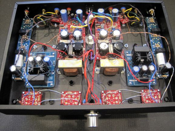
Although it took a lot of effort, the amplifier seemed to build itself. I love when this happens. When the internal logic, the logos, the blueprint, the design… is sound, assembling runs along, as the next required step is obvious. In contrast, when the design lacks a coherent internal logic, God save me, as completing the project feels like pushing a big rock up a steep hill. It's even worse than that, as it often feels as if you had to push the big rock up a steep hill filled with gigantic boulders and poisonous snakes. Yes, I know that is odd to use the word "logic" in the description of an analog circuit or device, but the study of logic contains much more than just true and false. For example in formal logic, strong, non-deductive arguments break into two categories: cogent and uncogent. Cogency, like beauty, lies in the mind of the apprehender. Well, this stereo amplifier's design was cogent, i.e. having the power to compel conviction or move the will. Moving the will is the important feature of a good design. Many stalled projects stem from a frozen will, a suspension motivation and willpower. What undoubtedly helped me this time was that I used a large chassis, 3in by 17in by 12in. In theory, I could have got away with an enclosure only 3in by 17in by 10in, but it would have proved a major headache to build. Using too small an enclosure is a trap that I have fallen into many times, far too many. Just because I can does not always mean that I should. I had planned of having a local laser-cutting business cut long narrow slits into the bottom panel cover, but I couldn't wait, so I drilled the 33 ventilation holes myself.
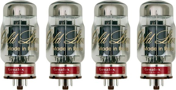
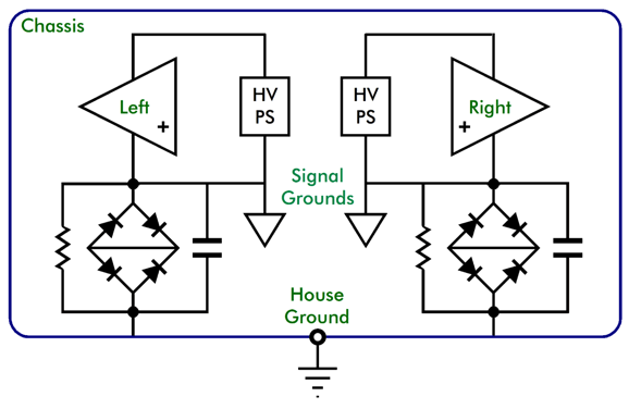
I used a variac and measured all the voltages without any tubes in place; all were good. Nonetheless, I didn't want to lose any new tubes in a catastrophic failure, so I plugged in used noval input tubes and 60-year-old used KT88 tubes that still had some life in them; once again, all the voltages were good. With my ear over the loudspeaker, barely perceptible hum emerged from the woofer, which was a good omen. Soon enough, music poured forth into my listen room. Single-ended-imbued music, free from grit, hardness, and stress. It was very good, but not perfect. I thought the bass was a tad flabby and midrange not up to the previous monobloc EL34/KT77 standard. I then switched out the old output tubes, replacing them with a new Russian Genalex matched quad of KT88 tubes, which instantly resulted in an obvious sonic upgrade. Tighter bass and greater clarity, but perhaps a tad too bright, too edgy. I had been using old Telefunken 12AX7 smooth-plate input and old Amperex 12AU7 second-stage tubes. Just for giggles, I replaced them with new Russian 12AX7s and JJ ECC802 long-plate 12AU7s. Mercy. The stereo imagining improved and the clarity was scary good—most importantly, the high-frequency edge was gone. (Mind you, the amplifier's many electronic parts might have just broken in enough to undo the edge, as I let the amplifier idle for a few hours before making the tube swaps, but my bet is that the blame lies with the old tubes.) I bought the quad set of matched Russian-made reissue of Genalex Gold Lion KT88 tubes from Antique Electronic Supply. "Matched" means different things to tube sellers. For some, matching involves setting up three bins, one labeled "low", one labeled "medium," and one labeled "high." Into these three bins all the tubes are sorted. Imagine if all men were sorted into short, average, and tall. Surely finer gradation would be welcome, otherwise the 5'6" man would fall into the same category as three footers, and the 6'1" would be grouped with professional basketball players. Antique Electronic Supply uses Apex Tube Matching®, which supercharges tube matching to a new level. How do I know? I tested all four KT88 tubes and they measured as if they were Siamese quadruplets. Tight matching is more important in my stereo single-ended amplifier, as each channel's parallel output tubes have joined cathodes and share a single constant-current source to ground. In addition, my amplifier is free of any negative feedback loops, so a matched quad delivers matched channels. My game plan— giving each channel its own power supply and ground, and then using two house-ground circuits to connect the separate grounds to the chassis, which in turn terminates into the house ground—works. It preserves the full potential of stereo imaging. Compared to my mono power amplifiers, the image is no less wide, no less deep. (See Post 434 for more on mono versus stereo power amplifiers.)
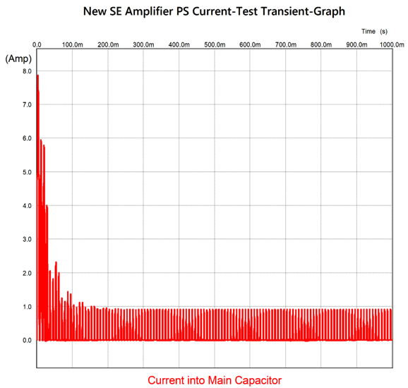
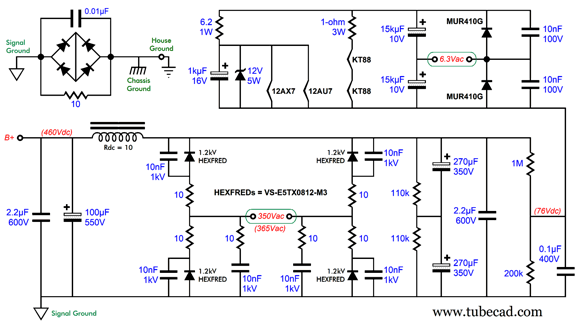
The AnTek AS-3T350, a 300VA/350Vac toroidal power transformer, rests atop the chassis inside a black metal can made by AnTek, which freed up much space within the chassis. It weighs 7 lbs, which contributes the amplifier's total weight of 33 lbs. Weirdly enough, it did not developed the B+ voltage that my calculations had predicted. Let's do the math, 350Vac peaks at 495V, so even with rectifier losses we would expect at least 490Vdc of B+ voltage. Instead, I got 460Vdc. What's up? The many small details add up in a high-voltage power supply. First of all, the 350Vac secondaries present a DCR of 25 ohms; in contrast, most low-voltage secondaries are made up from much thicker wire, which result in DCRs in the milliohms. Next, the hyperfast FRED rectifiers exhibit voltage drops of about 1V. Moreover, each rectifier is in series with a 10-ohm resistor. Thus, so far we are looking at a total oppositional charging resistance of 45 ohms, to which we must add the choke's 10 ohms of DCR, bringing us up to 55 ohms. As each channel draws about 160mA, this amount of resistance doesn't seem like it would make for much of a voltage loss, but the 0.16A is not the peak current flow through the rectifiers. The peak current flowing into large-valued power-supply capacitors is many times higher. How many times? Almost six times in this amplifier. I modeled the power-supply circuit in SPICE simulations and the peak charging current came in at 0.92A.
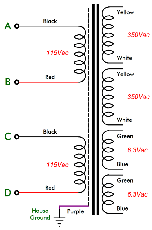
The graph displays the first one second of operation. Note the initial peak current flow of almost 8A. The SPICE simulations assume static secondary and inductor DC resistances, but as these devices heat up, so too, their DCRs rise. Here is the actual power transformer schematic, which differed slightly from the one at the AnTek website:
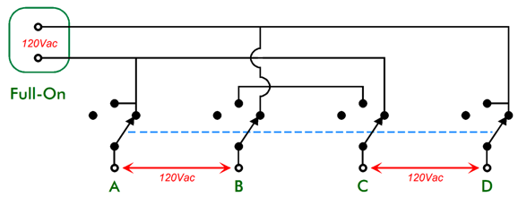
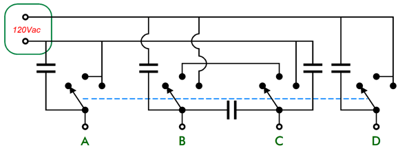
The transformer's PDF showed the 6.3Vac secondaries holding different colors, but the actual transformer had both of these secondaries using the green/blue wires. I have labeled the two input primary winding taps as A, B, C, and D to better illustrate the operation of the two-stage power switch. Perhaps you will recall Post 590's proposal of what the audio world needed was a two-stage three-position power switch.
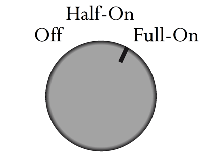
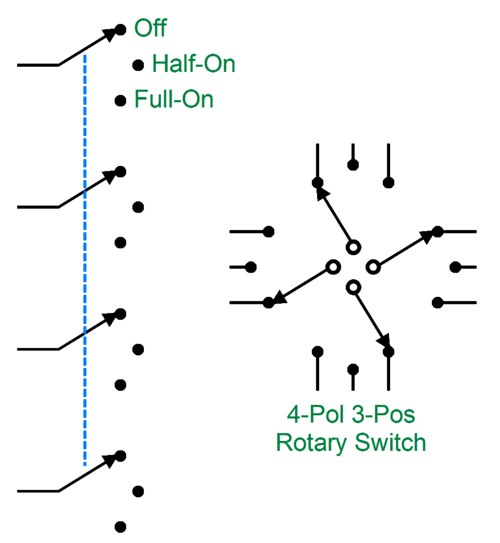
In order to make such a switch, a three-position rotary switch is needed, along with dual transformer primaries.
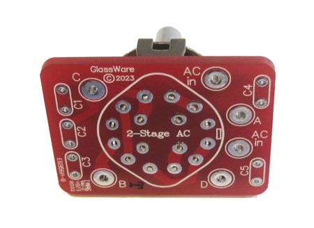
The 3-position rotary switch holds four poles, all of which move in tandem. Well, I decided that I needed such a switch, so I made one.
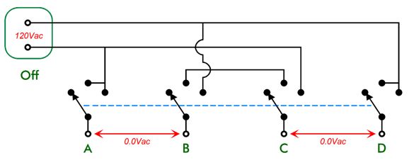
Here is the accompanying schematic with the rotary switch in the off position.
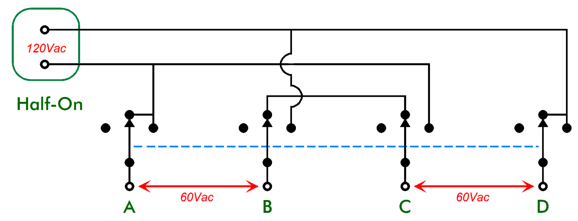
Next, in the half-on position:
Note that the two primaries only see half of the wall voltage, so the primaries deliver only half the normal voltages. Next, fully on:
Now, we get the full B+ voltage. This arrangement works nicely, with no snaps or pops, which is partially due to the inclusion of five 0.01µF ceramic capacitors, which I left out of the previous schematic for the sake of clarity:
Alas, this two-stage power switch only works in countries with 115Vac to 120Vac wall voltages. The choke is not the typical tube-based amplifier choke, as it is relatively low inductance and DCR, but high current (0.6A). Why? Long ago, a friend was complaining about how much ripple was coming out of his tube amplifier, which was an industrial design, not an audio-brand effort. I looked over the schematic and noted that no choke was used to filter the B+ voltage. As we walked out of my garage, I spotted a choke on a shelf. I gave it to him and explained that although it was not really suitable, as it offered so little inductance (and so low a DCR) for a tube amplifier, it would still be better than nothing. He called me the next day, proclaiming the marvelous transformation of his power amplifier into an audiophile-grade amplifier. Months later, I dug out a suitable choke, and we replaced the first choke. Not so good. The first inductor made for much better sound, in spite of its 100mH inductance and 4A current rating. The tube-applicable choke's much higher inductance did not yield better sound. I remembered this, as I searched through my box of chokes. His was a push-pull amplifier; mine a single-ended, so my reasoning might not be sound. The actual high-voltage secondary voltage was 365Vac due to my wall voltage being 120Vac, not 115Vac. The two 270µF capacitors in series present 135µF of capacitance with an effective voltage rating of 700Vdc. This is definitely overkill, but I like to play it safe. (Well, if I had to do it over again, I would use two 470µF/300V capacitors instead.) Now, the amplifier schematic: Most of the resistors are 1W carbon-film types. My Aikido-Mojo single-ended output stage trick of injecting a sampling of the power-supply noise into the cathodes of the KT88 output tubes worked well. I measured all the capacitors used in this circuit, and I was stunned that they were all on spec—to an amazing extent. For example, the 470µF capacitors measured 471µF and 469µF, which is far better than 1%.
The inside of the stereo power amplifier isn't as tidy (i.e. pretty) as I would like, but it was a breeze to wire everything up and I was in a hurry to hear it. By the way, about every five years, I end up soldering an electrolytic capacitor in backwards. Well, before applied the power, I made a quick visual check and found one. I fear that my five-year gap has narrowed to two years.
I am super pleased with the design. Of course, if I were to do it again, it would be different; for example, I would lay out two symmetrical PCBs, say 9in by 8in, which would hold everything needed for one channel, save for the transformers and chokes. Far less wiring would be needed. In addition, I would then have the option of building two mono power amplifiers. (A true apple-to-apple shootout would then be possible in the testing of stereo imaging between mono and stereo power amplifiers.) Moreover, the two PCBs would move the input tubes closer to the output tubes and would allow me to add two handles near the output transformers, which would make lifting the amplifier much easier. Moreover, the power supplies would be moved closer to the output tubes. So far, none of my audiophile buddies have heard the amplifier. Soon. I did, however, force my wife to listen to it. She claimed to like the sound, but wondered if the time spent in its creation was equal to the result. I pointed out that I could probably sell the amplifier for a few grand, which placated her. The power of money. I began this section with a philosopher, so I shall end it with another. As the Danish philosopher, Soren Kierkegaard, in 1846 pointed out in his ultra-fun book, The Present Age,
Load Inductor with Signal Gain
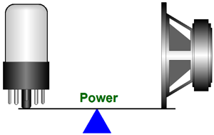
At no time do we get something for free, as cheating physics is against the universe's rules.
(Actually, we always lose a little in the exchange, the transformations of voltage and current, as real transformers are made from iron and copper.) Well, a center-tapped inductor can be used in place of an output transformer in some circuits.
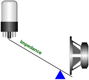
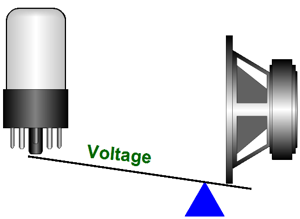
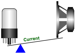
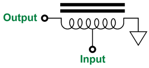
Since the tap occurs at 50% of the inductor's winding, the output-voltage swing halves, but the output-current doubles, bringing us to unity-power transfer. In other words, 100W goes in and 100W comes out. So why bother? Impedance mismatch is the good reason. If we bridge the output tap to ground with an 8-ohm load, such as a loudspeaker, the reflected impedance at the input is 32 ohms. Now, a 32-ohm load is far easier to drive with an OTL power amplifier than an 8-ohm load, as the OTL is current limited, but not voltage limited. Tubes can swing big voltages easily, but cannot deliver high current swings. In addition, a key feature that few know about is that the output inductor provides a great deal of loudspeaker safety, much like an output coupling capacitor would. How's that possible? The wire used in making the inductor presents very little DC resistance compared to the loudspeaker. If something goes terribly wrong in the OTL output stage, the milliohms of wire shunting the loudspeaker protects the woofer from DC over voltage. For example, say a high-voltage bipolar power supply is used, something like ±120Vdc, and the fuse in the positive power-supply rail blows, leaving the bottom output tubes still conducting, thereby yanking the output voltage down negatively. Well, the downward DC current yank will have little effect on the inductor's DCR, making for a trivial DC offset voltage across the loudspeaker. Wait a minute, John, isn't the whole point of an OTL amplifier no output transformer? First, a tapped inductor is not a transformer. Second, and more importantly, the center-tapped inductor's winding ratio is effectively 2:1, which is far better than the 5k output transformer's 25:1 winding ratio. Moreover, the current flowing through the inductor is the current the loudspeaker directly sees, but magnified. In other words, the inductor's iron core has less injurious effect on the resulting output. In addition, much like an autoformer (which is actually a variation on the tapped inductor), a 4 lbs. center-tapped inductor will deliver twice the output power than a comparable 2:1 output transformer weighing 4 lbs. Okay, now I will turn the table around. What if we apply the input signal to the center-tap and take the output at the inductor's beginning?
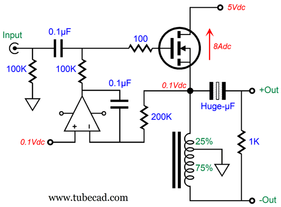
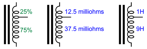
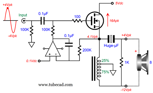
If we attach an 8-ohm load to this inductor output tap, the reflected impedance at the input will be 2 ohms. Since an OTL amplifier is inherently current limited, this would be a bad arrangement. On the other hand, solid-state gear is often voltage limited, but seldom current limited. For example, your smart phone can probably deliver 1Vp into 32-ohm headphones, which most will find plenty loud—but not all headphone listeners. For example, 300-ohm-headphone users would like a bit more output voltage swing. Well, if we attach a 300-ohm load to this inductor, the reflected impedance at the input will be 75 ohms, and the output voltage doubles (+6dB louder as a result). Still not enough? We can place the tap along the inductor's winding at 33%, which effectively creates a winding ratio of 3:1. If we attach a 300-ohm load across this new inductor, the reflected impedance at the input will be 33.3 ohms, while the output voltage triples (+9.54dB louder as a result). If the phone can comfortably drive 16-ohm headphones, we could use an inductor with the tap at 25%, resulting in +12dB of signal gain. Let's now think about driving loudspeakers with this inductor tapped at 25%. The 8-ohm loudspeaker appears as a 0.5-ohm load at the tap—a frighteningly-low impedance no doubt. We can, however, design a power amplifier for just about any impedance. With the inductor tapped at 25%, the power amplifier will have to deliver four times the current, but only one fourth the voltage swing. But as transistors and MOSFETs have no problem dumping gobs of current flow, we could build a power amplifier with a seemingly crazy-low B+ voltage. First, let's do the math for amplifier that delivers 16W into an 8-ohm load. Sixteen watts requires 16Vpk and 2Apk into an 8-ohm load, which means we could easily get away with using a bipolar power supply of ±20Vdc. Sixteen watts into 0.5 ohms requires 4Vpk and 8Apk, which implies a bipolar power supply of ±5Vdc. If we go the single-ended and inductor-loaded route, a monopolar power supply of +5Vdc is all that is needed.
Appearances to the contrary, this is a voltage amplifier, not a power buffer, as the amplifier delivers signal gain; 4Vpk goes in and 16Vpk comes out. The tapped inductor might present 100mohms of DCR and 10H of inductance. Both resistance and inductance add when in series. The reason the inductance does not follow the same ratio of 1-to-4 that the DC resistance does is that inductance arises due to the number of turns of wire, which must be squared. Thus, as the bottom of the inductor holds three times the turns, it presents 3² times the inductance. The implicit four-to-one winding ratio implies an impedance ratio of sixteen-to-one.
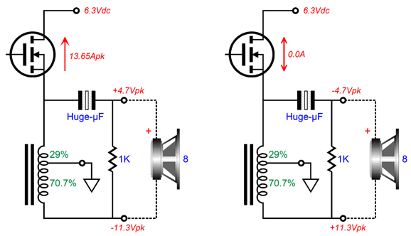
The DC voltage drop across the top 25% of the winding is only 0.1Vdc, which implies an idle current flow of 8A, which the DC servo establishes and maintains. Now, 100mV of DC offset might not hurt many loudspeakers, but it is still bad form—thus, the inclusion of the output coupling capacitor, which could have a voltage rating of only 6.3V to 10V. Let's see what an input signal of 4Vpk does at the output.
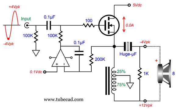
The loudspeaker sees a total of +16Vpk across its voicecoil. When the input sinewave goes to -4Vpk, the following results:
Now, the total voltage equals -16Vpk, and the MOSFET undergoes no current flow. A peak current of 16A and minimum flow of 0.0A averages out to 8A, the idle current flow, which vouchsafes this output stage as a class-A one. At idle, the 8A of current flow against the 5V B+ voltage produces 40W of heat dissipation from the MOSFET. The MOSFET will get hot, which implies a big and heavy heatsink. The amplifier efficiency is equal to 16W/40W or 40%, a bit lower than the theoretical efficiency of 50% for an inductively loaded class-A amplifier. If you are wondering where the tubes are, wonder no longer.
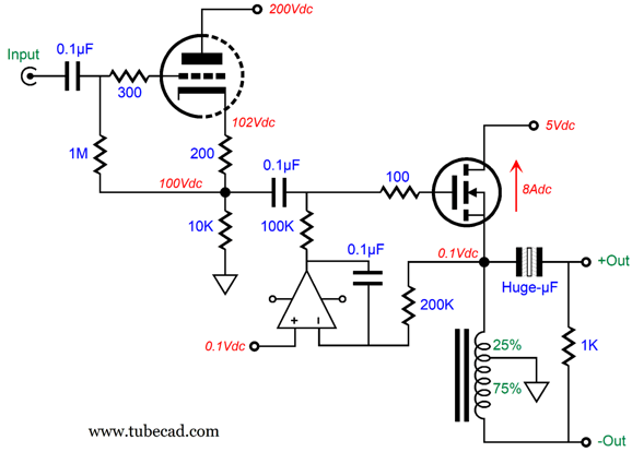
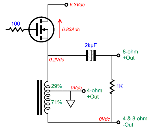
The cathode follower input stage provides no signal gain, but it does deliver the current needed to drive the MOSFET's relatively high input capacitance. So far, I have used the inductor tapped at 25%, as it lends itself to easier math examples. If we move the tap to 29%, we get something truly useful: 8-ohm and 4-ohm outputs.
Assuming an inductor DCR of 0.1 ohms, at the 29% tap the DRC will be 29 milliohms, which divided into 0.2Vdc gives us an idle current flow of 6.83A. The 29% tap also implies a winding ratio of 1-to-3.4, which in turn implies a voltage ratio of 1:3.4 and a current ratio of 3.4:1, which further implies that that the idle current of 6.83A will be—at peak power output—reduced to 2Apk into an 8-ohm load and 2.83Apk into a 4-ohm load from the ground to the negative output terminal.
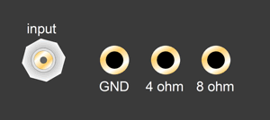
In other words, we get 16W of output into either a 4 or an 8 ohm load, as long as the correct output terminals are used, much like the several output-impedance taps on a tube-based output transformer.
Yes, solid-state power amplifiers can and should have several output-impedance taps.
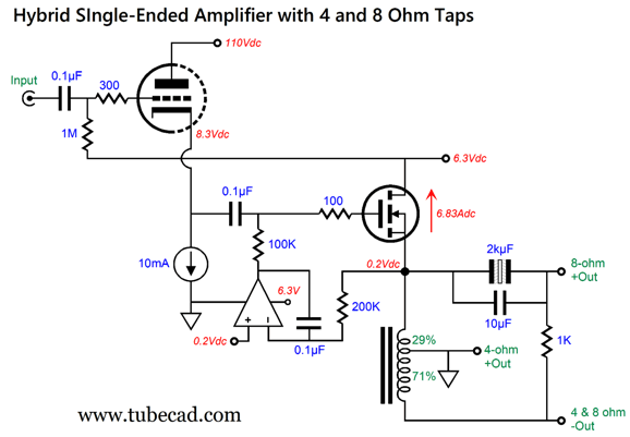
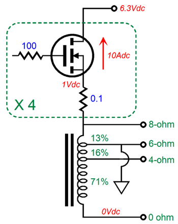
No doubt many are suffering from a math-induced headache right now. Sorry. The math does work, however. It shows that we can gain a great deal of usability from a simple tapped inductor. Note that the idle current flow of 6.83A against B+ voltage of 6.3Vdc results in a dissipation of 43W, which is not too different from the previous design example's 40W, which was optimized for 4.5 ohms and 8 ohms. Moving the inductor tap to 29% moves the two impedances to 4 and 8 ohms. Okay, we finally get to the end, which was my actual beginning. When I came up with the following single-ended amplifier circuit, I knew that I could never start with it, as the mental leap would prove too far for too many. In explicating electronics, the shortest path is often the steepest. Note that the only the 8-ohm output sees the output coupling capacitor. Since no current flows through the bottom 71% of the inductor winding at idle, no DC offset voltage can arise. This is a nice feature, as a 4-ohm loudspeaker would require an output coupling capacitor with twice the capacitance. The OpAmp must be chosen with care, as the 0.2V reference voltage is very close to the ground potential that the OpAmp's negative power-supply terminal attaches to and the bias voltage the MOSFET need will be around 4.5Vdc. In other words, a rail-to-rail OpAmp will be needed. Also note that since the triode's cathode is much closer to ground, in terms of voltage, the 6.3Vdc B+ voltage can be used to power its heater element. In other words, only two power-supply-rail voltages are needed. Switcher power supplies that put out low voltages at high currents are common and relatively cheap, one fifth the cost of an audiophile-grade fuse. The inductor must, however, be made from the same high-grade iron used in the making of audio-output transformers, not power-supply choke iron. In addition, it must hold an air-gap, much like a single-ended output transformer. Okay, I acknowledge that for many 16W is too paltry to contemplate. Well, what about 100W? If we parallel up four output MOSFETs and up the total idle current to 40A per channel and use a different multi-tapped inductor, we could get 100W of single-ended glory.
I added a 6-ohm tap and that tap is grounded. No output coupling capacitor is used, as I assume that very thick gauge wire will wrap around a large air-gapped toroidal core. Moreover, not that much inductance is needed, say only 130mH across the entire winding. Thus, we might be able to do only 13 turns of wire to reach the 6-ohm tap, then 16 turns, and then 71 turns of 16-guage copper wire. If these 100 turns of wire fail to create 130mH of inductance, we could double number of turns between taps. The 8-ohm tap needs to only swing 5.2Vpk relative to ground to establish 100W of output, which explains the still low B+ voltage of 6.3Vdc. The more I think about, the more I believe that something closer to 7.5Vdc will be need, as the voltage drop across each source resistor will equal 2Vpk at full output. Imagine a stereo power amplifier with two 6DJ8s protruding from the chassis top, a top that is also home to three large toroid cans, and two massive heatsinks flanking the enclosure. Now, imagine that Elon Musk were a tube-loving audiophile and had read this post, whereupon he concluded that this amplifier must be built, so he could hear it. "Damn the expense man, just do it and send me the bill." Well, I can dream, can't I?
Music Recommendation: Mozart, Beethoven, Mahler, Shostakovich, and Bernstein have had movies made about their lives. Actually, I remember seeing a movie about Liszt in the 1970s. I wondered how many movies about classical composers have been made that I didn't know about. At Reddit, I found this list:
Looking over the list, the obvious omission is Sergei Rachmaninoff, who at 6'6" tall and with huge hands lived an extraordinary life. Netflix, what are you waiting for? Returning to Lou Harrison, another album of his music that I can recommend is Serenado. His five-part Serenade for Guitar is well worth listening to. In adddition, the first track offers some audiophile delight.
//JRB
Did you enjoy my post? Do you want to see me make it to post 1,000? If so, think about supporting me at Patreon.
User Guides for GlassWare Software
For those of you who still have old computers running Windows XP (32-bit) or any other Windows 32-bit OS, I have setup the download availability of my old old standards: Tube CAD, SE Amp CAD, and Audio Gadgets. The downloads are at the GlassWare-Yahoo store and the price is only $9.95 for each program. So many have asked that I had to do it. WARNING: THESE THREE PROGRAMS WILL NOT RUN UNDER VISTA 64-Bit or WINDOWS 7, 8, and 10 if the OS is not 32-bit or if it is a 64-bit OS. I do plan on remaking all of these programs into 64-bit versions, but it will be a huge ordeal, as programming requires vast chunks of noise-free time, something very rare with children running about. Ideally, I would love to come out with versions that run on iPads and Android-OS tablets.
|
I know that some readers wish to avoid Patreon, so here is a PayPal button instead. Thanks.
John Broskie
John Gives
Special Thanks to the Special 89 To all my patrons, all 89 of them, thank you all again. I want to especially thank
I am truly stunned and appreciative of their support. In addition I want to thank the following patrons:
All of your support makes a big difference. I would love to arrive at the point where creating my posts was my top priority of the day, not something that I have to steal time from other obligations to do. The more support I get, the higher up these posts move up in deserving attention. If you have been reading my posts, you know that my lifetime goal is reaching post number one thousand. I have 382 more to go. My second goal was to gather 1,000 patrons. Well, that no longer seems possible to me, so I will shoot for a mighty 100 instead. Thus, I have just 11 patrons to go. Help me get there. Thanks.
New URL of the GlassWare website |
|||||||||||||||||||||||||||||||||||||||||||||||||||||||||||||||||||||||||
| www.tubecad.com Copyright © 1999-2025 GlassWare All Rights Reserved |

