| John Broskie's Guide to Tube Circuit Analysis & Design |
| March 15 2025 | Post Number 617 |
||||
Single-Ended 15W Stereo Amplifier
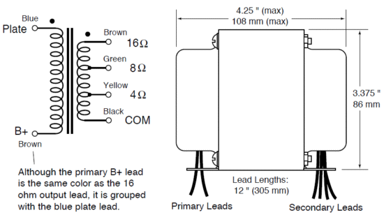
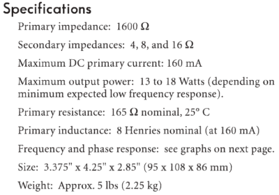
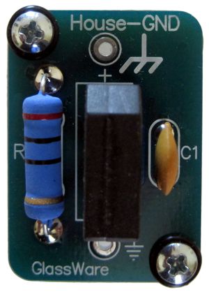
For me, the best feature was the low primary impedance, as it necessarily implies a low winding ratio. A good general rule is that the lower the winding ratio, the better the performance in terms of distortion. (Just compare a 1:1 audio transformer to a 20:1 transformer.) The math is simple: Winding Ratio = √(Primary/Secondary) In this example, 14.14:1 for an 8-ohm load; 10:1 for 16-ohm load. I fell in love with the UBT-1 transformers, so bought two additional pairs, which have sadly languished in my closet. Well, my new project, a stereo version of my mono amplifiers, grants two UBT-1s a new home. I am convinced that the best stereo imaging comes from two mono power amplifiers, as the shared ground connection in a stereo power amplifier works against this goal (as does the shared house-ground connection with two mono power amplifiers). If that is true, why am I building a stereo power amplifier? I am keen to see (hear) if I can overcome the problem of a shared ground in a stereo power amplifier. (In addition, after 30 years of use, my mono power amplifiers are in need of power-supply capacitor re-cap and general rebuild. In other words, I do not want to be left amplifier-less.) My workaround is to effectively build two mono power amplifiers on one chassis, with each holding its own power supply, and with the chassis grounded to the house ground, to which each channel's ground connects through one of my House-GND circuits.
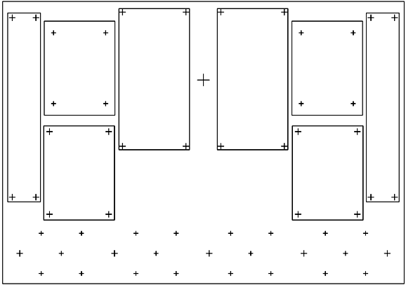
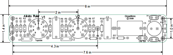
The chassis is a Hammond black-coated steel "Bud Box" 3in tall and 17in wide and 12in deep. First of all, I hate working with steel. It's so much tougher to drill and punch than aluminum, but at the same time it is much stronger, which the heavy output and power transformers require. I gave up on using a ruler and pencil to mark all the drill-hole locations. My Cannon inkjet printer can accept poster paper 19in by 13in big, so I laid out all the drill-hole placements for the top panel my vector drawing program.
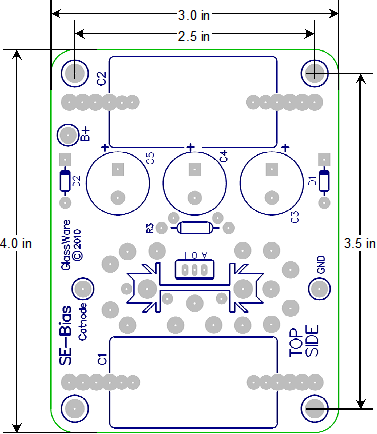
Each rectangle represents a PCB. Not shown are the four squares for the 2in octal power-tube socket PCBs, as each channel gets two output tubes, so four octal power tubes will sit at the front of the power amplifier.
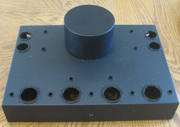
After printing the sheet, I measured the spacing between drill marks to ensure that the printer actually printed at 1:1 scale; it did (something many laser printers do not actually do). Next, I taped the sheet to the top of the enclosure with painter's blue masking tape. Before hammering drill-punch marks, I placed the chassis atop a stack of hard wood small enough to fit the 16.5in by 11.5in opening at the bottom, so as to prevent excessive bending due to my heavy hammer blows. I hoped to drill through the paper, but my tiny drill press could not accommodate the large chassis, so I used my DeWalt battery-powered hand drill to make the pilot holes. The stiff poster paper just got in the way of drilling, alas. The secret to successful steel-metal fabrication are new drill bits and machine oil. The bright Colorado sun shows the resulting drill holes.
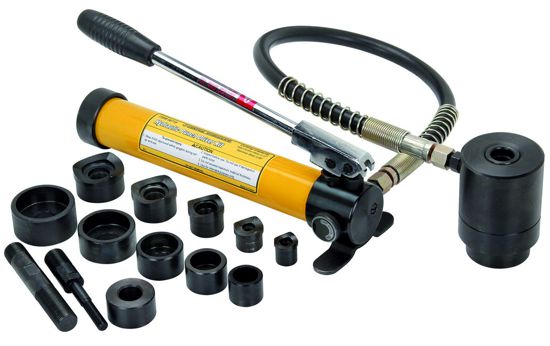
The next step was to drill bigger holes where needed and to punch the biggest holes. By the way, if you didn't heed my advice from Post 369, where I urged everyone to buy their PITTSBURGH 14-piece hydraulic punch driver kit for just $99, you are missing out on the best deal I have ever seen.
With this punch-driver kit, making the following is easy.
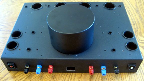
The four KT88 tubes hug the front edge of the chassis.
The blue output terminals are for 4-ohm speakers; the red, for 8-ohm speakers. Note the super short path from the RCA input jacks to the input tube. The AC power inlet rectangular punch-out was made by my Auber rectangle metal punch, which I detailed in Post 603, which can only be used with a hydraulic driver. The large cylinder is for securing the AnTek AS-3T350 - 300VA 350Vac toroidal power transformer atop the chassis, which gives much room inside the chassis and less AC hum potential.
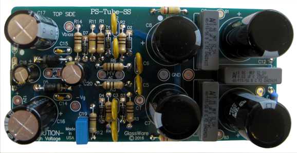
First of all, this is a huge (300VA) power transformer for 15W stereo power amplifier. In fact, it is even more powerful than it seems, as it was built to work with either 50Hz or 60Hz wall voltages, which means that it is 60/50 times more powerful here in the USA than it would be in a 50Hz country; in other words, 360VA. In addition, the all the secondary voltages will be 120/115 times greater, as my wall socket puts out 120Vac, not 115Vac; thus, the high-voltage secondaries will deliver 365Vac, not 350Vac. Now, 365Vac rectifies up to about 516Vdc. Note the four secondary windings, which means each channel will get its own high-voltage and low voltage windings. Each channel's separate power supply will reside on one of my 3in by 6in PS-Tube-SS PCBs.
And here is the schematic:
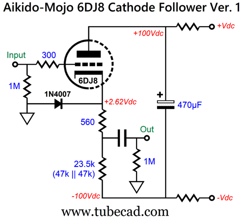
Due to the 365Vac secondaries, I will have to use extra high-voltage capacitors, with capacitors C7 and C8 being 350V capacitors The two are in series so effectively become a single 700V capacitor), and C11 and C13 being 500V capacitors. In a class-AB tube power amplifier, the output stage should connect to B1; in my single-ended amplifier, the connection will be made from B2, as the class-A nature of the single-ended output stage means a steady current flow from the power supply. The input stage, an Aikido gain stage, will attach to B3. The nominally 6.3Vac winding will attach to the 5Vac eyelets, as I plan on running all the tubes with a DC voltage. The two output tubes, matched KT88s, will have their heater elements in series. (There a reason for this arrangement; namely, I will use an auto-bias constant-current source circuit to provide cathode bias for the two KT88 tubes, which will share a cathode connection to the constant-current source circuit. If one KT88 is missing or has an open heater, the other KT88 will not be requires to absorb the missing tube's current conduction.) Of course, I will be implementing my signature single-ended Aikido-Mojo technique, which I revealed back in 1999, in Volume 1, Issue 2.
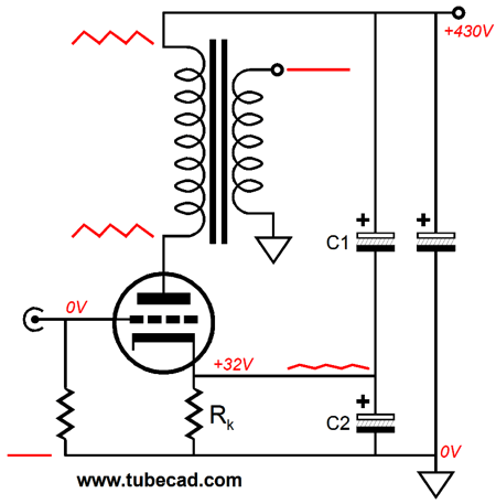
Post 276 offers additional details. The quick recap is that by injecting a small portion of the power-supply noise into the output triode's cathode, we can induce a deep power-supply-noise null on the secondary. The amount of needed power-supply noise depends on the output triode. (This Aikido Mojo technique does not work with pentodes, only triodes.)
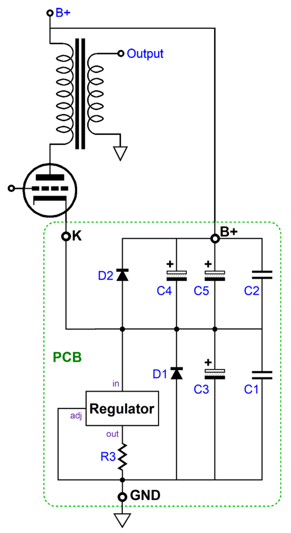
Here is the schematic:
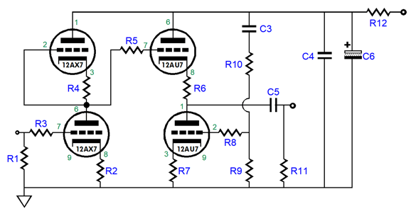
With triode-connected KT88s, the top capacitor should be 66µF, while the bottom capacitor is 490µF. The 66µF is easy to make out of two 33µF/500V capacitors in parallel, while the bottom capacitor can be made from a 470µF/63V electrolytic capacitor in parallel with a 20µF/100V non-polarized electrolytic capacitor. (Of course, I will actually hand measure each capacitor to ensure the actual values are realized. In addition, I will add two film bypass capacitors, C1 and C2.) An LM317-HV can probably do the job within its safe voltage limit; if not, the TL783 will be used. (Diode D1, could be replaced by a zener, which would safeguard the IC voltage regulator.) The input stage is a classic Aikido gain stage:
Since the 12AX7's amplification factor (mu) is 100, the final gain will approach 1:50 (+34dB), which should be enough to drive the pair of parallel output tubes to full output, with around 1Vpk of input signal. I aim for a B+ voltage after resistor R12 of about 300Vdc. The Aikido PCB is long and thin:
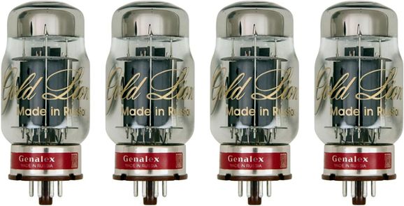
The project has advanced nicely, but has stalled as I await parts delivery. I am super eager to hear if the separate grounds and power supplies are enough to deliver monobloc imaging. In addition, it will be interesting to hear what the new-production Genalex Gold Lion KT88 tubes sound like triode-connected in a single-ended power amplifier.
Tube-Based Crossovers Part 2
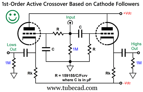
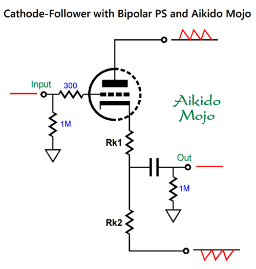
Even if the cathode followers deliver far less than unity-gain, say only 0.8 (-1.9dB), the two filter outputs sum to flat. Of course, this simple active crossover can be improved by adding two safety diodes, which would bridge the cathodes to ground, so that at startup, when the cathodes are still cold and not conducting, the maximum negative cathode will be only -0.7V. Other improvements might be to replace the cathode resistors with constant-current source, which would allow us to run a far lower-voltage negative power-supply rail, which in addition could power the heater elements. Another enhancement, which would not require using solid-state supporting devices, would be to add some Aikido Mojo.
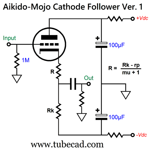
The additional cathode resistor creates a bipolar power supply noise null at the cathode follower's output. What is going on here is that the triode and resistor R increase the triode's effective plate resistance (rp) by (mu + 1)R. When the triode's effective plate resistance equals that of the cathode resistor Rk, the two resistances define a two-resistor voltage divider whose nexus sits at the power-supply noise null, just as -1 + 1 equals 0.
This assumes that the positive and negative power-supply rails present the same amplitude of ripple, but in anti-phase to each other. (A miss-tapped secondary center-tap on the high-voltage winding will create an imbalance in ripples, which will undo some of the Aikido-Mojo technique. The workaround to a miss-tapped center-tap is to place a resistor or inductor in series with the center-tap and ground.) Here is a design example:
The math is easy:
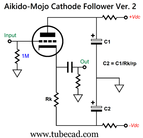
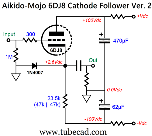
On the other hand, if we desire the lowest possible output impedance and/or the closest approximation to true unity-gain, we can use just one cathode resistor, but fiddle with the power-supply's RC filter's capacitor ratio, which will alter the amplitude of ripple on each power-supply rail.
Without the secondary cathode resistor, the triode presents a much lower impedance than the cathode resistor, so creating power-supply noise null requires making a complementary imbalance in bipolar power supply ripples.
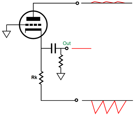
Here, again, is a design example with a 6DJ8-based cathode follower:
2nd-Order Crossovers
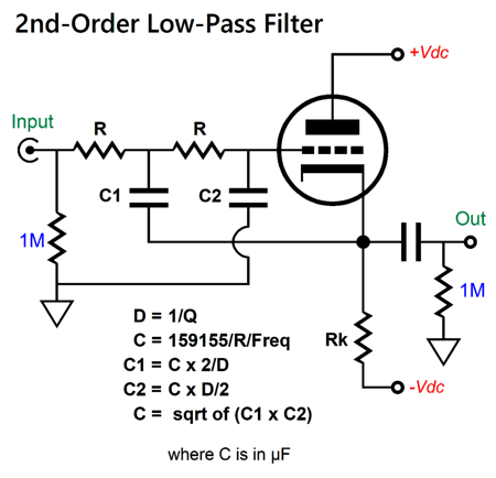
Once we move up from 1st-order filters, going to 2nd, 3rd, and 4th-order filters, we run into the problem of the cathode follower failing to achieve true unity gain. For example, the following tube-based 2nd-order low-pass filter runs into the problem that the textbook formulas, formulas which work perfectly with OpAmps, do not yield the same desirable results with the cathode follower. This is a dang shame, as the formula for the part values is so simple with a Linkwitz-Riley 2nd-order alignment: C2 = C1 and R2 = R1
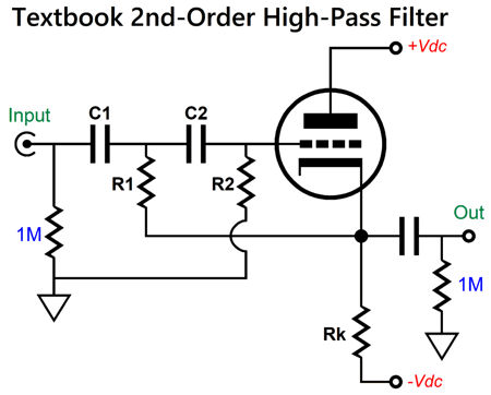
Nor does the tube-based 2nd-order high-pass filter work any better.
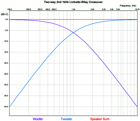
In general, the higher the triode's amplification factor (mu), the closer the cathode follower comes to realizing unity-gain output. Since, the 12AX7 offers a mu of 100, it might seem to be the perfect choice for the cathode follower. Sadly, the 12AX7's high plate resistance and low permissible cathode current flow undo the increased-gain advantage. Before going into the details, we must accept that the only useable 2nd-order crossover filter alignment is the Linkwitz-Riley, not the Bessel or the ever popular Butterworth. The Butterworth alignment, with its Q of 0.707, has both loudspeaker drivers down -3dB at the crossover frequency, but fails to sum to flat.
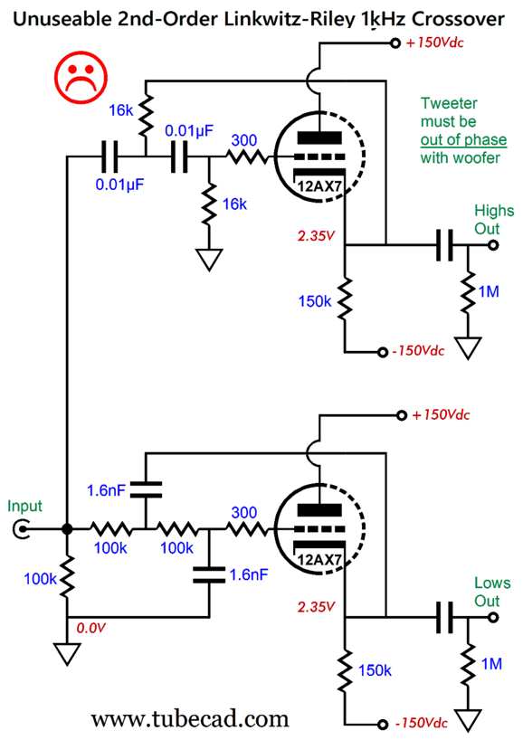
In contrast, the Linkwitz-Riley alignment exhibits a Q of 0.5 and has both drivers down -6dB at the crossover frequency. If we use the textbook formulas and build the following two-way active crossover, we do not get not textbook results.
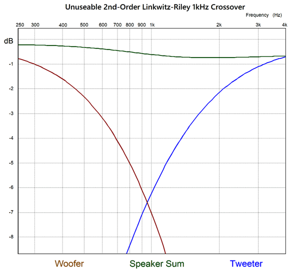
If you actually do the math, you will find that part values actually imply a crossover frequency of 994.7Hz, not 1kHz. That is not why this circuit earned the unhappy face. This is the reason:
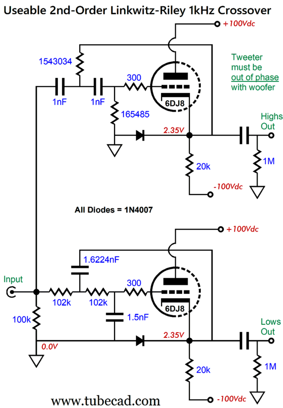
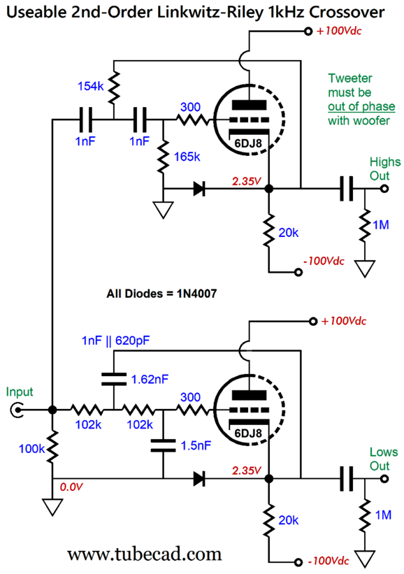
In addition to not summing to a flat output, the 12AX7's trivial 1mA of idle current flow and its relatively high output impedance of 600 ohms makes it unsuitable to drive either long interconnects or power amplifiers with low input impedances. In addition, the crossover frequency is actually 945Hz. Okay, what would a useable tube-based active 1kHz 2nd-order crossover look like?
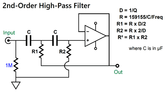
The bipolar power supply rail voltages have been reduced to ±100Vdc, but the idle current has been increased to 5mA. Moreover, the 6DJ8-based cathode follower offers an output impedance of around 100 ohms. These three changes were not enough in themselves to make this active crossover useable, as the filter part values needed to be skewed, which was the hard part. The 2nd-order Salen-Key active filter actually employs some positive feedback, as a portion of the output signal is fed back into its input. Just how much is fed back determines the frequency-selective gain it delivers; this is labeled "dampening" in active filter design. Dampening is the inverse of Q, so a Linkwitz-Riley alignment with a Q of 0.5 exhibits a dampening of 2, which results in both outputs being halved in amplitude at the crossover frequency. In contrast, the Butterworth's Q of 0.707 has a dampening (D) of 1.414. We can universalize the 2nd-order Salen-Key high-pass filter to the following:
We can see that with a Q of 0.5 and a dampening of 2, resistors R1 and R2 will equal resistor R. With a Q of 0.707 and a dampening of 1.414, resistor R1 will equal R/1.414 and R2 will equal 1.414R. Well, we can view the cathode follower's departure from unity-gain as its Q, so its dampening is the inverse of its gain, i.e. 1/gain. Thus, if a cathode follower's gain is 1:0.9, its Q is 0.9 and its D is 1.111…. In other words, the cathode follower comes pre-dampened. If we factor in its intrinsic dampening into the formulas, we can achieve our desired active crossover slopes and flat summation from the drivers. SPICE simulations revealed a D of 1.04 for the 6DJ8-based cathode follower. This means that we need a D 1.04 times smaller; thus, with the Linkwitz-Riley Q of 0.5 and D of 2, we must use a D of 1.923. T he high-pass filter requires us to fiddle with the resistor values, which is easy, as resistors come in a huge range of values. In contrast, the low-pass filter requires altering the capacitor values, which is tough. (Read my last post.)
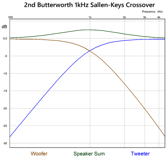
Following these formulas can lead to some dang awkward values of capacitors. Thus, I approached the problem from a different angle. I knew that capacitor C1 would have to be larger in value than C2 by the inverse of the cathode follower's gain squared or 1.0816 times larger. I then multiplied this number against the commonly available capacitor values until I found a result close to another commonly available capacitor. I started with 1 and ended at 1.5, as 1.5 x 1.0816 equaled 1.6224, which is close to 1.6 the next commonly available capacitor value. I then took the square root of (1.5 x 1.6224), which I then used to calculate R's value, using the following formula: R = 159155/C/Freq The closest 1% value was 102k. By the way, 1.6224nF is only 1.4% higher than 1.6nF. This brings up the issue of the optimal placing of capacitors in parallel to arrive at a desired value not made. We could use a 1.6nF capacitor in parallel with 22pF, but should we? My answer is no. Here's why: 3% tolerance is tight for a high-quality film capacitor, with many only being 10% tolerance. In other words, 3a % tolerance 1.6nF capacitor can actually measure between 1.552nF to 1.648nF, with this last value exceeding the target capacitance and making the addition of the 22pF pointless. My recommendation is to strive to find two capacitor values that are close to each other. For example, let's say that the target capacitor value is 3.1nF. I would place a 1.6nF in parallel with a 1.5nF capacitor, never a 3nF in parallel with a 100pF capacitor. The 3% tolerance 1.6nF capacitor can actually measure between 1.552nF to 1.648nF, while the 3% tolerance 1.5nF can actually measure between 1.455nF to 1.545nF, so the potential 3% range of parallel capacitances is 3.007nF to 3.193nF, with the statistical chance of being closer to 3.1nF. How so? If we get the 3% low value of the 1.6nF capacitor and the high value of the 1.5nF capacitor, the two in parallel will yield 3.097nF; in contrast, with the 3% low value of the 3nF capacitor and the high value of the 100pF capacitor, the two in parallel will yield 3.013nF. Okay, what if we reversed the situation? If we get the 3% high value of the 1.6nF capacitor and the low value of the 1.5nF capacitor, the two in parallel will yield 3.103nF; in contrast, with the 3% high value of the 3nF capacitor and the low value of the 100pF capacitor, the two in parallel will yield 3.187nF. Here's a mental picture: Imagine the 1.5nF bell-curve of distribution almost overlaying on the 1.6nF bell-curve of distribution, whereas the 100pF bell-curve of distribution would appear far to the right of the 3nF bell-curve of distribution. As you might guess, I tend to approach most problems from a functional/mathematical perspective. By the way, many have been asked to list their preferred pronouns. I haven't. Last year, while waiting in line to renew my driver license at the DMV, I heard those ahead of me asked to give theirs. I wasn't asked, damn it. Why, damn it? I want to be asked, as I have a ready answer: "Before we get to my preferred pronouns, I must declare my preferred adjectives: insightful and creative. I regret that I do not know you well enough to reveal my preferred verbs…" perhaps the dour DMV employee could spot my being an old trickster by my seeming eagerness. Well, after doing my preferred mode of thinking, here is result:
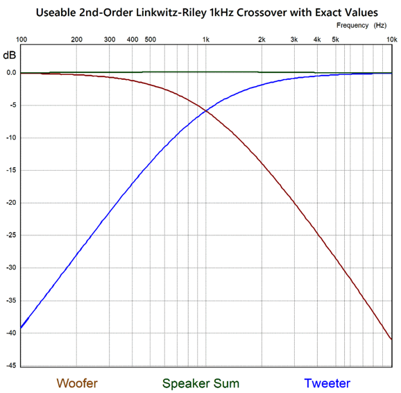
Here is the resulting frequency graph:
We can buy tight-tolerance 1nF and 1.5nF capacitors and 1% 102k resistors, the rest of the filter part values must be made up from either paralleling parts or placing parts in series. Or must we? I ran some SPICE simulations on the same crossover circuit but with commonly available part values that were fairly close to their target values.
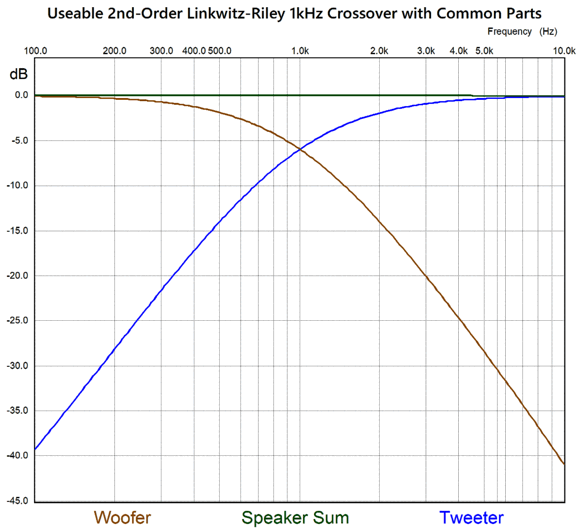
Here is the resulting frequency graph:
Stunningly close. Partly this is due to luck; but my having carefully selected many of the parts before to include commonly available values, such as the 1.5nF capacitor, also helped.
3rd-Order Crossovers
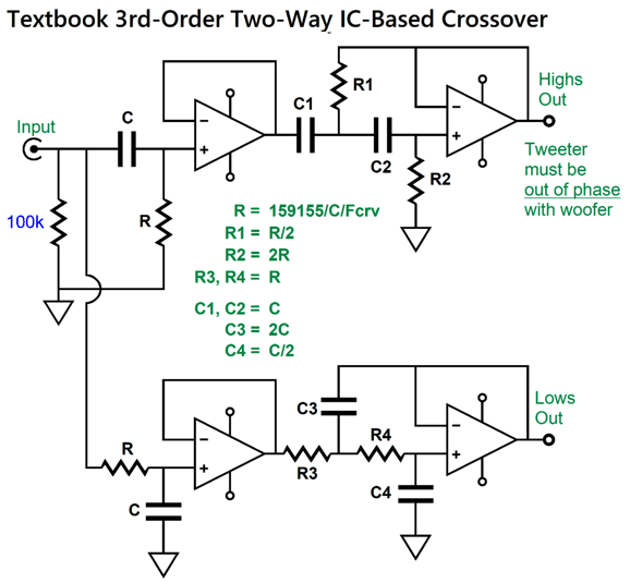
If we were building a 2nd-order rumble high-pass filter for use with LP playback, we might be able to get away with using just one cathode follower. Since an active crossover must do more than just selectively attenuate based frequency, but also sum at least two loudspeaker drivers to a flat combined output, we need the additional cathode follower. This means that we will cascade a 1st-order filter with a 2nd-order filter. The 1st-order is super easy and almost impossible to mess up, however, it does not allow for any dampening adjustment, which means that this task must fall to the 2nd-order filter. A 3rd-order crossover, whether active or passive, must have the loudspeaker drivers down -3dB at the crossover frequency to sum to flat. This means Butterworth filter alignment, not a Bessel or Gaussian (3rd-order Linkwitz-Riley does not exist). Since the input 1st-order filter delivers the needed -3dB output at the crossover frequency, the following 2nd-order filter must have a Q of 1 and, by extension, a dampening of 1. In other words, no dip at the crossover frequency, as the 1st-order filter's Q of 0.707 is multiplied against the 2nd-order's Q of 1, resulting in a final Q of 0.707. Let's look at an OpAmp-based two-way 3rd-order active crossover to get a feel for what is required.
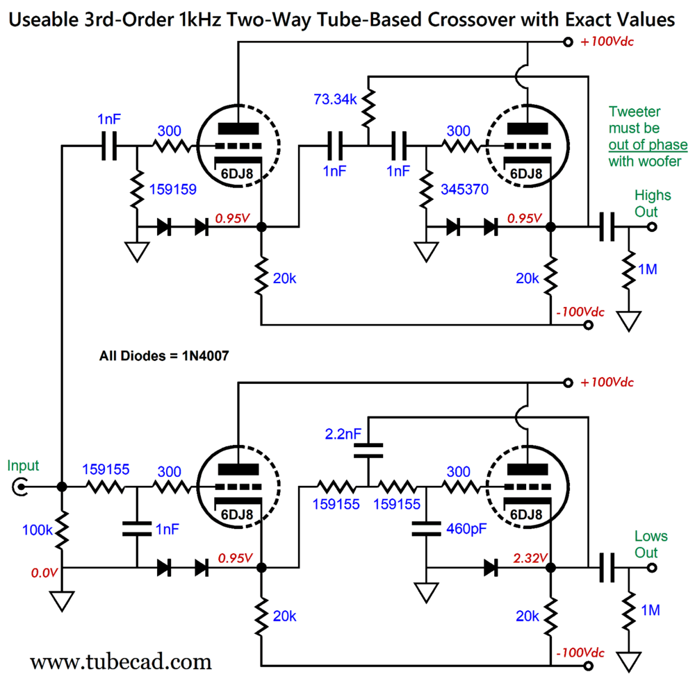
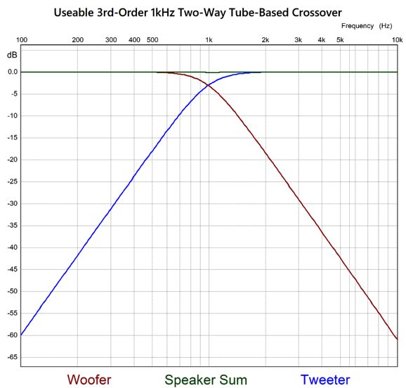
Note that resistor R2 is four times larger than R1 in value, and that capacitor C3 is also four times larger in value than C4. These two ratios result in the 2nd-order filters having a dampening of 1. With cathode followers being pre-damped, as it were, we must decrease the 2nd-order dampening to compensate. In other words, the 4-to-1 and 1-to-4 ratios must be expanded a tad. By how much? By the inverse of the cathode follower's gain squared. With the 6DJ8-based cathode follower, by 1.085, as each cathode follower's gain came in at 0.96. Thus, R1 = R/2/1.085 C3 = 1.085 x 2 x R Here is the result for a 3rd-order 1kHz two-way crossover:
In general, math gets us close, so I was nervous to see how this cathode-follower-based crossover would fare in SPICE simulation. I need not have worried.
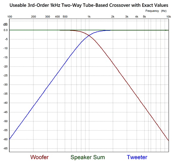
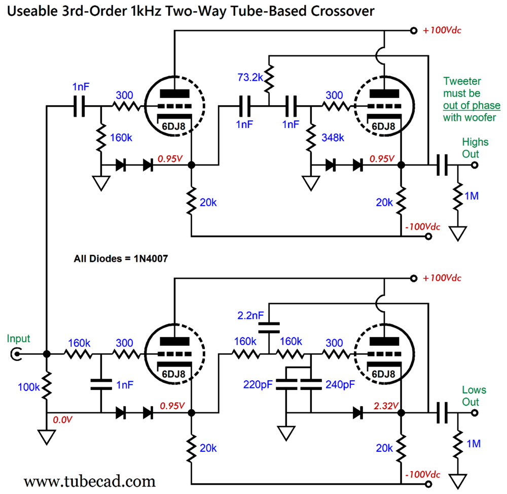
Truly impressive. Next, I ran simulations on the same active crossover with communally available part values.
No 460pF capacitor is made, so the 220pF and 240pF capacitors are placed in parallel. The resulting SPICE-generated frequency plots reveal a certainly useable 3rd-order crossover.
A slight dip of 0.1dB occurs at the crossover frequency. Trust me, real loudspeaker driver exhibit many decibels of deviation from ruler flat.
4th-Order Crossovers
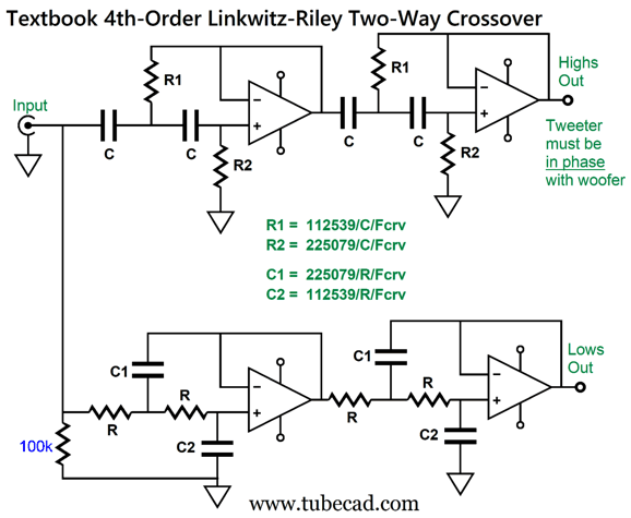
Once again two triodes per filter will be needed, as two 2nd-order filters are placed in series. The only filter alignment that sum to a flat frequency response is the Linkwitz-Riley. Making a 4th-order Linkwitz-Riley crossover is easy with OpAmps.
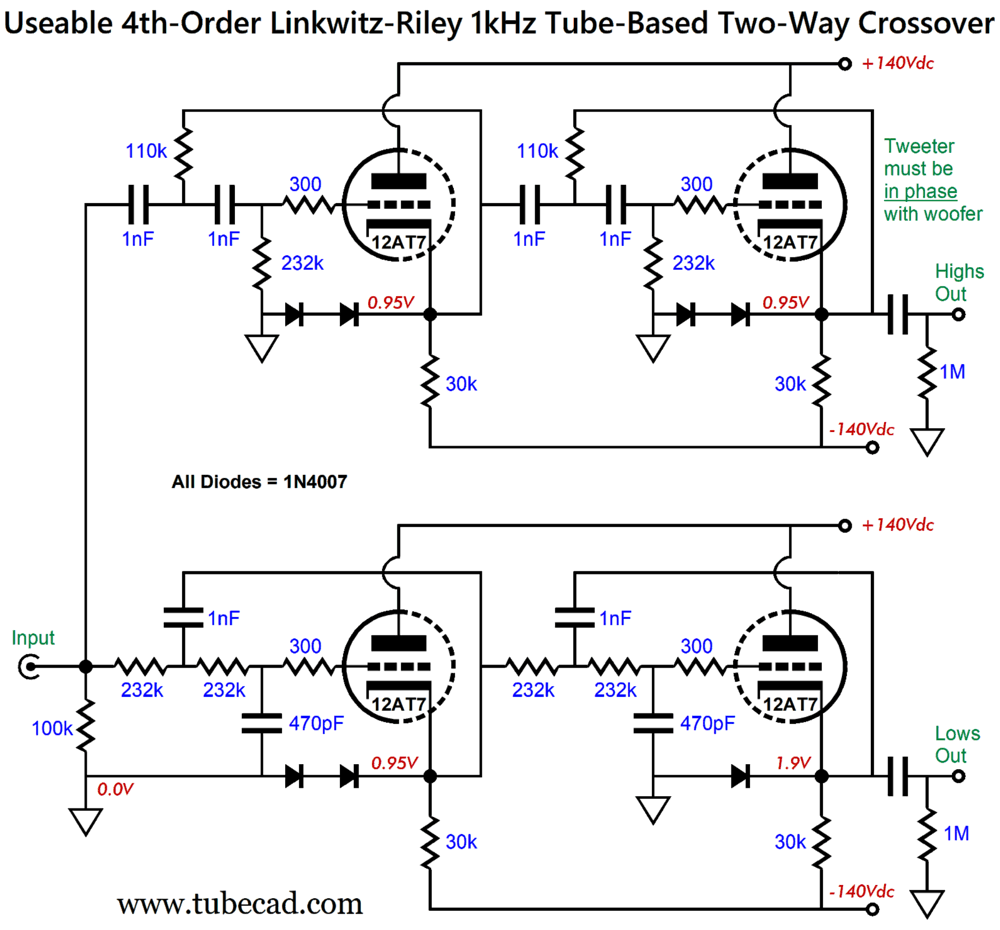
Effectively, the 4th-order Linkwitz-Riley filter is made up of two 2nd-order Butterworth filters in cascade. The Butterworth filter presents a Q of 0.707, which when multiplied together equals a Q of 0.5, which implies both loudspeaker drivers being down -6dB at the crossover frequency. The high-pass filter is the easier one to actually build, as resistors come in far greater array of values than do capacitors. So the first step is to choose a readily available tight tolerance capacitor value for capacitors C, let's say 1nF, and then calculate the resistor values. With the low-pass filter, however, we run into the problem of limited capacitor values. If we examine the low-pass filter formulas, we see that capacitors C1 are twice the value of capacitors C2. This means that we first choose pairs of capacitors that double evenly, such as 1nF and 2nF, 1.1nF and 2.2nF, 1.5nF and 3nF, 7.5 and 15. In other words, capacitor values such as 3.3, 3.9, 4.3, 4.7, 5.1, 5.6, 6.2, 6.8, and 9.1 do not have a doubled partner in the commonly available values. Then we solve for resistors R. R = 225079/C1/Fcrv Where C is in µF. With two cathode followers in place of two OpAmps, this capacitor workaround won't work, as the capacitor values to not adhere to easy 2-to-1 ratio, but to something greater than two to one. For a design example, I decided to use the 12AT7 in place of the 6DJ8, as some dislike 6DJ8 tubes and as the 12AT7's higher mu of 60 results in a closer approximation to unity-gain output. The higher the mu, however, the higher the B+ voltage needs to be to realize healthy idle current flow.
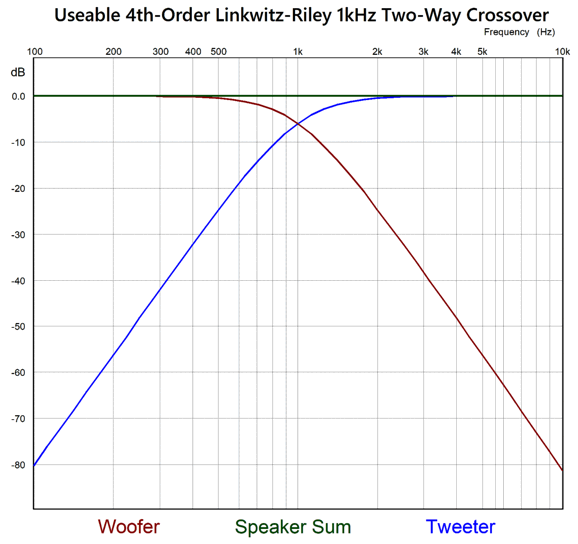
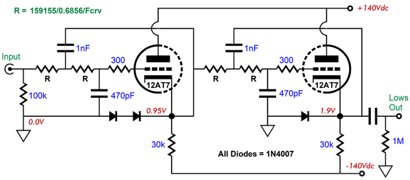
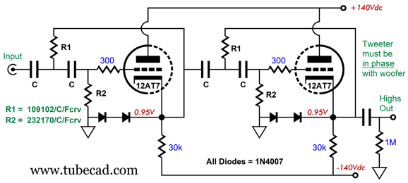
The 12AT7 triodes each idle at 4.7mA and dissipate 0.65W of plate dissipation. The 30 cathode resistors can be made up from placing two 15k resistors in series. All the part values are readily available. I would never think of actually building this crossover without the added safety diodes. (In other words, the all too common audiophile practice of leaving out any part the builder doesn't understand why it's there in the schematic must be avoided. Ignorance of function is no excuse—it's also dangerous.) The ratio of 2.128 to 1 was found to work best to undo the 12AT7-based cathode follower insertion loss of gain. Here are the SPICE-generated frequency plots.
With the exception of the low-pass filter's output exceeding -80dB at 10kHz, the results are identical to those provided by OpAmps. Why the discrepancy? The 232k resistors and the triode's own input capacitance explains the slightly greater attenuation at 10kHz. What if you desire a 100Hz crossover instead? Easy. Just use 10nF capacitors in the high-pass filter and 10nF with 4.7nF capacitors in the low-pass filter. What about 700Hz? Retain the 1nF and 470pF capacitors in the low-pass filter and follow this formula:
The number 0.6856 is the square root of the product of two capacitors (1 and 0.47) multiplied against each other. The 159155 is the inverse of 2pi multiplied by a million, which normalize the result for use with µF capacitance. The high-pass filter grants us much more latitude in capacitor value choice.
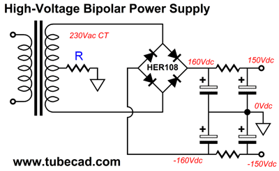
The 4th-order crossover allows us to bi-amp with a horn ribbon or planar or AMT midrange/tweeter driver and a woofer, as it offers great protection of the delicate high-frequency driver and little overlap between drivers. This last advantage is worth examining. The false assumption behind all crossovers is that the two loudspeaker drivers are fullrange enough to allow meaningful frequency-response and phase-response overlap at the crossover frequency. As crossovers do not just cross over, they overlap outputs. Real loudspeaker drivers deliver limited frequency responses—why else would we need a crossover? The 4th-order crossover creates very little meaningful overlap between drivers, so the combined driver sound output relies less on the drivers exhibiting wide frequency response or even being physically time aligned on the cabinet. In other words, the 4th-order crossover is something of a compromise, but then so too are the loudspeaker drivers. In Heaven, all loudspeaker drivers are fullrange and all crossover are 1st-order. The fact that we can build such an active crossover with just two tubes per channel is amazing. Moreover, the circuit isn't too complicated for point-to-point wiring. Even the high-voltage bipolar power supply would not be too difficult to wire up, as most high-voltage power transformers offer center-tapped secondary.
Music Recommendation: Cassandra Wilson's New Moon Daughter Wilson can sing, and she can compete with the best jazz singers. In fact, the album won the Grammy Award for the Best Jazz Vocal Performance in 1995. Audiophiles will delight in the 192kHz, 24-bit version of the album available for streaming at Qobuz and, partially available, at Amazon Music. Only partially, as not all of the album's tracks are in high-res at Amazon, strangely enough. Be sure to turn on your subwoofers and fasten your mental safety belt before playing the first track, "Strange Fruit," Billie Holiday's classic song.
//JRB
Did you enjoy my post? Do you want to see me make it to post 1,000? If so, think about supporting me at Patreon.
User Guides for GlassWare Software
For those of you who still have old computers running Windows XP (32-bit) or any other Windows 32-bit OS, I have setup the download availability of my old old standards: Tube CAD, SE Amp CAD, and Audio Gadgets. The downloads are at the GlassWare-Yahoo store and the price is only $9.95 for each program. So many have asked that I had to do it. WARNING: THESE THREE PROGRAMS WILL NOT RUN UNDER VISTA 64-Bit or WINDOWS 7, 8, and 10 if the OS is not 32-bit or if it is a 64-bit OS. I do plan on remaking all of these programs into 64-bit versions, but it will be a huge ordeal, as programming requires vast chunks of noise-free time, something very rare with children running about. Ideally, I would love to come out with versions that run on iPads and Android-OS tablets.
|
I know that some readers wish to avoid Patreon, so here is a PayPal button instead. Thanks.
John Broskie
John Gives
Special Thanks to the Special 89 To all my patrons, all 89 of them, thank you all again. I want to especially thank
I am truly stunned and appreciative of their support. In addition I want to thank the following patrons:
All of your support makes a big difference. I would love to arrive at the point where creating my posts was my top priority of the day, not something that I have to steal time from other obligations to do. The more support I get, the higher up these posts move up in deserving attention.
If you have been reading my posts, you know that my lifetime goal is reaching post number one thousand. I have 384 more to go. My second goal was to gather 1,000 patrons. Well, that no longer seems possible to me, so I will shoot for a mighty 100 instead. Thus, I have just 11 patrons to go. Help me get there. Thanks.
New URL of the GlassWare website |
||||


| www.tubecad.com Copyright © 1999-2025 GlassWare All Rights Reserved |