| John Broskie's Guide to Tube Circuit Analysis & Design |
| February 20 2025 | Post Number 616 |
|||||||||||||||||||||||||||||||||||||
SRPP Circlotron
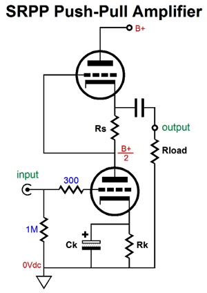
The current-sense resistor, Rs, creates the needed anti-phase AC signal to drive the top triode in anti-current phase to the bottom triode, thereby creating push-pull operation. The SRPP is load dependent, which means that resistor Rs must be optimized to match the external load impedance. In other words, one resistor value does not fit al loads. In contrast, a push-pull output stage that receives a balanced set of input signals can drive a wide range of load impedances. As the bottom triode creates the top triode's input signal, if the bottom triode ceases to conduct, the top triode loses the controlling current flow from the bottom triode; thus, the strict need for true class-A push-pull conduction throughout the expected output voltage swings. Next, the Circlotron topology.
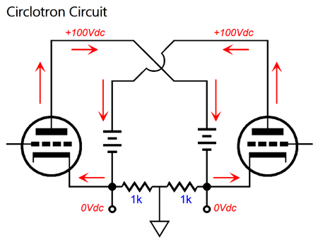
Circlotron output stages can be made from pentodes, MOSFETs, and transistors. The most famous Circlotrons use tubes. The two triodes operate in anti-phase when amplifying a balanced set of input signals. Yes, amplify. The Circlotron delivers gain, nearly 1:2 (+6dB), even when only one triode sees an input signal at its grid and we replace one triode with a constant-current source. In this latter case, this Circlotron will still deliver a balanced output, but it will function as a single-ended amplifier. This creation of gain is a result of the Circlotron's defining feature: the ground attaches mid load. If the ground attaches to either triode's cathode, the circuit ceases to be a Circlotron. Sadly, tubes require high plate voltages to deliver lots of current, which makes OTL driving of 8-ohm loudspeakers tough and 4-ohm loudspeakers almost impossible with tubes. In contrast, one-dollar MOSFETs can deliver gobs of current with very little drain voltage. The following is a very simple SRPP-Circlotron amplifier based on MOSFETs.
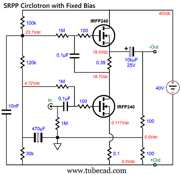
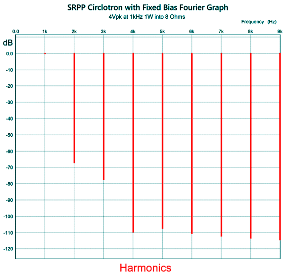
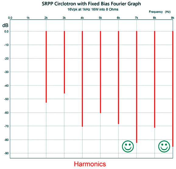
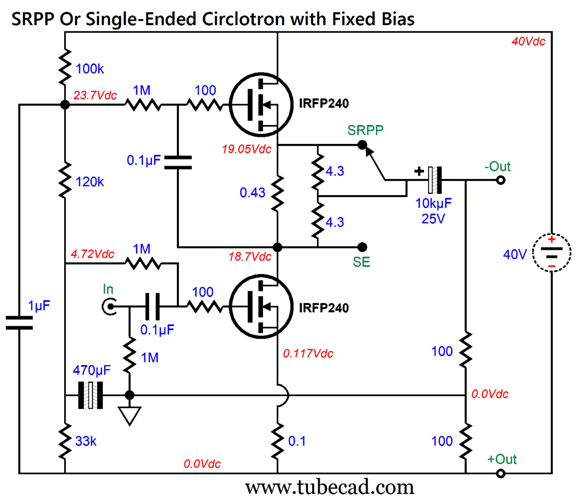
A few key features stand out. The first is that this Circlotron is arrayed vertically, not the usual horizontal layout, additionally, only one floating power supply is used. (See posts 253 and 290 and 368.) That's right, the 40Vdc power supply is floating, i.e. not grounded. It is this floating power supply and the ground attaching to the nexus of the two 100-ohm resistors in series that shunt the two outputs that makes this a Circlotron. This circuit is also a full bodied SRPP, as the push-pull operation is the result of an anti-phase signal being created by the varying current flow through a current-sense resistor. The idle current is a healthy 1.07A, which in theory allows for up to 16Vpk of output voltage swing into an 8-ohm load, which translates into 16W; 16W of class-A push-pull output. Each MOSFET must dissipate about 20W of heat at idle, making a per channel total of 40W and 80W for a stereo power amplifier, so big heatsinks are required. (A stereo power amplifier would also require two floating power supplies.) Ideally, the two MOSFETs should be matched, which is pretty much assured if they both come from the same production run, as modern electronic fabrication has steadily improved over the last half century. Here is its SPICE-generated Fourier graph with 4Vpk at 1kHz, the output stage delivering 1W into an 8-ohm load.
The first watt is the most important watt and what a pretty first this is, with a THD below 0.1% and more 2nd harmonic than 3rd. At full output, 16Vpk and 16W, the THD rises to 0.6% and the push-pull-harmonics signature expresses itself.
But not completely, as the 7th and 9th harmonics are nicely attenuated. Even the 2nd and 4th harmonics are not all that much attenuated relative to the 3rd and 5th harmonics, especially when compared to other push-pull output stages.
The current swings between top and bottom MOSFETs are fairly well balanced.
In SPICE simulations, this fixed-bias arrangement proved amazingly indifferent to external temperature changes. As I do not fully trust these SPICE-derived results, the following is an auto-bias version.
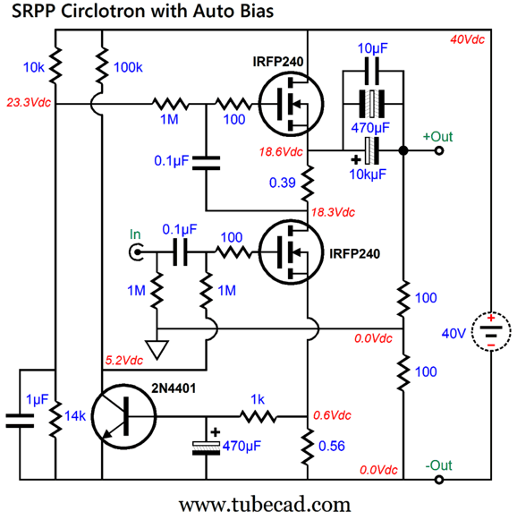
The 2N4401 NPN transistor monitors the voltage drop across the 0.56-ohm source resistor, striving to maintain an average voltage of 0.6V across the resistor, which in turn maintains constant average current flow of 1.07A through the two MOSFETs. (The 1k resistor and 470µF capacitor form an RC low-pass filter that filters away the AC signals above 0.34Hz, leaving only the average DC voltage at the transistor's base.) Note that I snuck in some extra bypass capacitors across the output coupling capacitor. The problem with this setup is that the bottom MOSFET's transconductance falls off substantially due to the 0.56-ohm source resistor. Here is the formula: gm' = gm / (1 + gm·Rs) You can see that even if the MOSFET offered infinite transconductance, the new effective transconductance cannot exceed 1/0.56 or 1.78A/V, quite a drop from the IRFP240's 6.9A/V. We could bypass the resistor with a capacitor, but the capacitor's value will be huge. How huge? To apply enough bypass capacitance to ensure low-frequency bandwidth down to 20Hz requires a 14.2kµF capacitor. True, the capacitor's voltage rating need only be 3Vdc. Additionally, the DC servo may peak at some low frequency, due to all the capacitors producing phase shift. Another way to implement auto-bias would be to use an OpAmp to monitor the voltage drop across the current-sense resistor, Rs, which would allow this resistor to serve two useful purposes. By the way, what got me reinterested in this topology was my search through my SPICE files for the single-ended version of the circuit, wherein the top MOSFET acts as a compliant-constant-current source (CCCS).
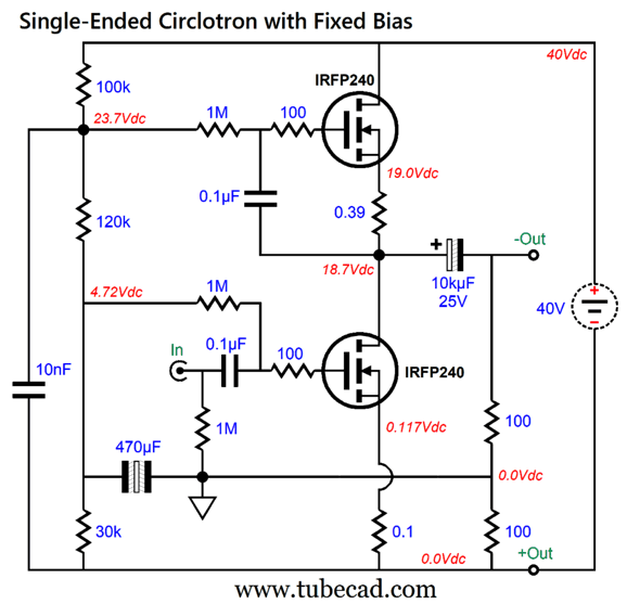
Once again strict class-A operation is necessary, so the same heat dissipation at idle results. Worse, the potential power output quarters. In other words, where the SRPP version with an idle current flow of 1A delivers 16W of output into an 8-ohm load, this single-ended version with the same B+ voltage and idle current only delivers 4W. To get to half the output, i.e. 8W, requires upping the idle current to 1.414A; 16W, 2A. Now, 2A against the B+ voltage of 40Vdc results in 80W of heat dissipation, twice that of the SRPP version delivering the same 16W of output. The thing is what if the single-ended version's meager 4W of output sounded fabulous? Quality over quantity? You can buy a 300B-based OTL power amplifier that delivers only 1W. Some audiophiles do buy such an amplifier and are happy for having done so. What if we had the option to select between the two modes, push-pull and single-ended? We need only add a toggle switch that could connect the output coupling capacitor to either the top MOSFET's source (SRPP push-pull) or to the bottom MOSFET's drain (single-ended). Of course, the switch must only be flipped with the power amplifier turned off, but often "of course" doesn't obtain. As St. Paul might have put it: For the smart thing that I would do, I do not; but the dumb thing, which I would not do, that I do. Here is my workaround:
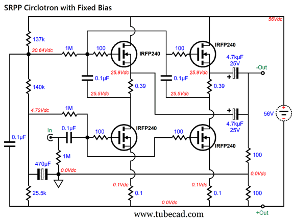
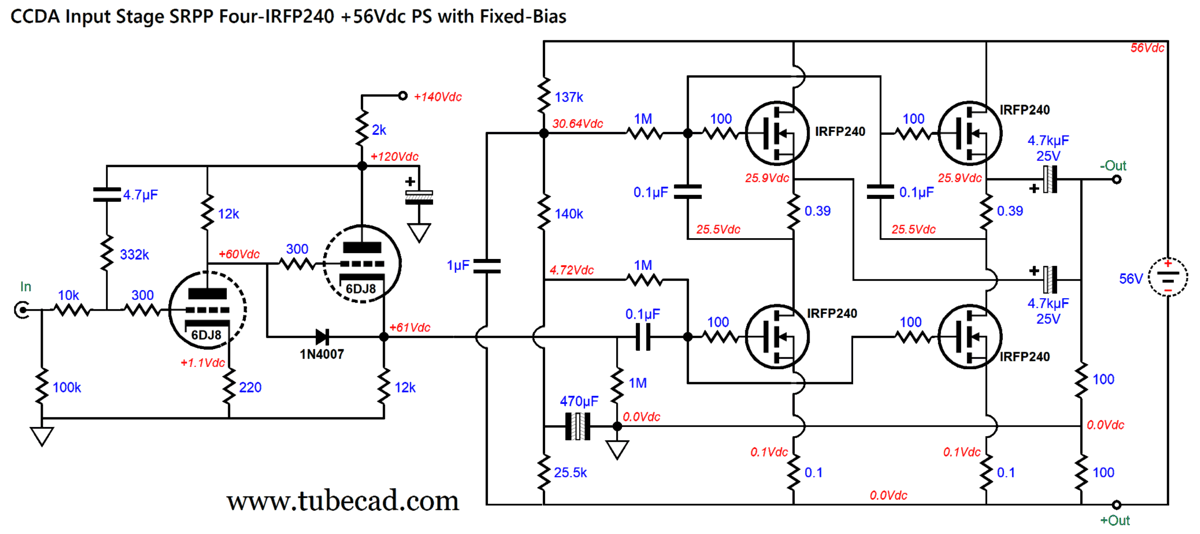
With the switch's contact flipped up to the SRPP connection, the top 4.3 is shorted out, leaving only the bottom 4.3-ohm resistor in parallel with the 0.43-ohm current-sense resistor, making a combined resistance of 0.39 ohms. Magic! Or, rather, dang sneaky. While the switch's contact moves between positions, the two 4.3-ohm resistors retain a connection to the contact, easing the voltage transition. We can double up on MOSFETs to spread the heat dissipation more evenly across the heatsink. In addition, the effective transconductance doubles, thereby instantly halving the output impedance, which falls to below 0.2 ohms. Or, taking advantage of the doubled MOSFETs, we could increase the B+ voltage on the floating power supply, but retain the 1A idle current through each MOSFET. A peak output current swing of 4A implies 64W of output into an 8-ohm load and 32W into a 4-ohm load. Sadly, 4Apk against 8 ohms equals a peak output voltage swing 32Vpk, which in turn implies a floating power supply voltage of at least 68Vdc, which would create 34W of heat dissipation from each MOSFET. Class-A operation is not for sissies. On the other hand, if we limit ourselves to 56Vdc, the amplifier could deliver 40W into an 8-ohm load and 32W into a 4-ohm load. I picked 56Vdc due to the availability of 56V/4A switching power supplies, which can be had of about $75. Here is what such an SRPP-Circlotron output stage would look like:
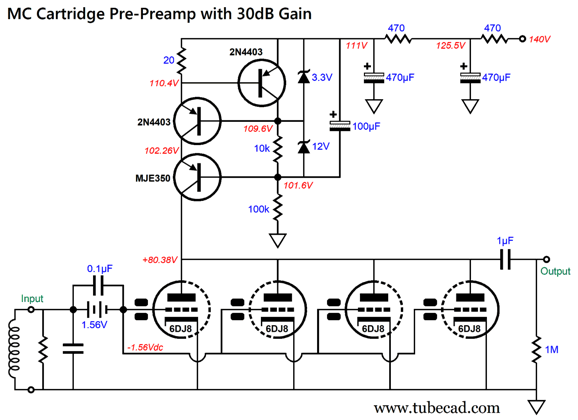
I gave each of the top MOSFETs its own current-sense resistor and each bottom MOSFET its own source resistor, as this arrangement works to undo any mismatching between MOSFETs. Two output coupling capacitors are needed, but since they are effectively in parallel, each can be half the value of a single output capacitor. As I have pointed out, the Circlotron is a gain stage, with a gain close to 1:2 or +6dB. To get 40W of output power into an 8-ohm loudspeaker requires a peak voltage swing of a little over 25V, so this SRPP-Circlotron will need about 13Vpk of input signal to be driven to full output. What signal source will provide the 13Vpk? A robust tube-based line-stage should be up to the task. (The MOSFETs relatively high input capacitance requires current to be driven at high frequencies. In other words, a 12AX7-based line-stage amplifier will not cut it.) The simplest tube-based frontend amplifier that I can imagine is a constant-current source loaded grounded-cathode amplifier. The problem with this circuit is that many fear making a solid-state high-voltage constant-current source. Here is an example of what such a high-voltage constant-current source would look like:
A 1.5V battery (AA or AAA) is used to bias the four 6DJ8 triodes. The battery is effectively not used, as it doesn't deliver and current into the grids, so its long shelf-life, about 8 years, means that it only needs to be replaced when the tubes are. The two black rectangles represent a ferrite bead. The zeners only engage when something goes wrong. An alternative circuit would be the constant-current-draw amplifier—but with added Aikido Mojo.
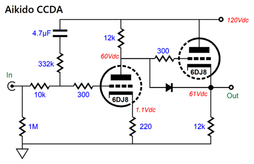
The added 332k resistor and 4.7µF capacitor inject just enough of the power-supply noise to provoke a ripple null at the output. This trick assumes that the signal source presents a low output impedance. Adding the CCDA to the Circlotron output stage is easy enough:
The PSRR of the tube-based input stage is -101dB in SPICE simulations (with a 220µF RC capacitor on the input stage), but as the Circlotron delivers a gain of close to two, the PSRR worsens to -96dB at the output. The output current balance is good between top and bottom MOSFETs.
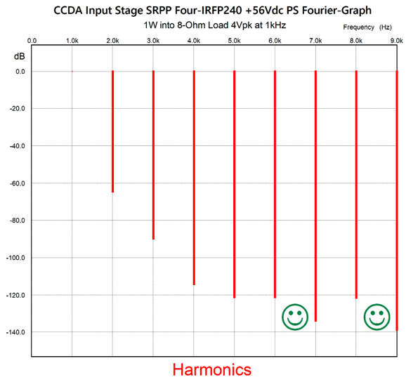
Note that we have not left the class-A window of current conduction, as no MOSFET has ceased to draw current. The distortion is plenty low and very single-ended at 1W of output.
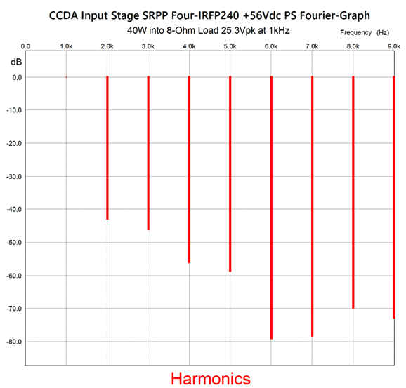
At full output, the push-pull nature of the SRPP topology becomes evident.
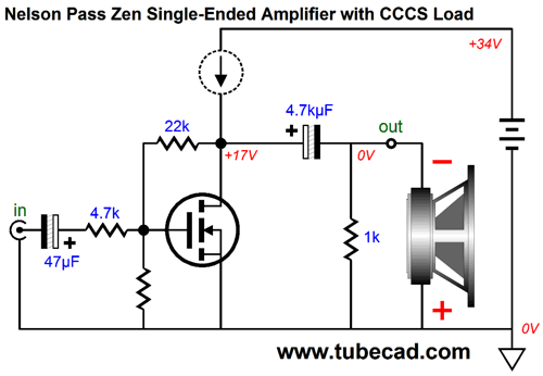
The THD is still below 1%, which is pretty amazing for a negative-feedback-free power amplifier. Actually, it's more like a global-NFB-free amplifier, as the Circlotron configuration actually bestows an intrinsic degenerative negative feedback. This is one of the reasons that I was interested in this topology. In contrast, the Nelson Pass Zen amplifier topology configures the amplifier as an inverting amplifier with a negative feedback loop that that spans from the input to the output.
Low-valued negative-feedback resistors must be employed since the MOSFET exhibits huge input capacitance—otherwise the high-frequency bandwidth prematurely falls off. For example, the IFRP240 presents an input capacitance of 1.3nF (1300pF), which compared to the 300B's meager 24pF is simply staggeringly huge. Even with the tube-based CCDA input stage, this amplifier's high-frequency bandwidth extends to about 500kHz:
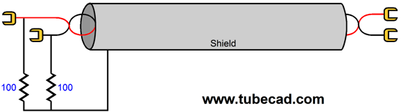
The intended power amplifier was a conventional unbalanced type. Thus, I did not want to ground the shield, as I wanted the shield to share the same voltage differences with both wires, something that would happen with a balanced-output amplifier, but not an unbalanced one. In other words, I wanted to create balanced-lite cables. See my Post 242 for more details. My latest thought is that all loudspeakers should include an extra binding post or jack on the back of the enclosure near the input terminals. Why? So we can "ground" the speaker baskets, frames, and magnets. I am told that doing so with the house ground makes for a more relaxed, effortless sound. Well, the loudspeaker cable shield can deliver the amplifier ground to the loudspeaker driver structures. Of course, if we have a transformer-coupled amplifier, especially if (or, perhaps, only if) it does not employ a negative feedback loop.
If we double up on the number of output tubes, the 16-ohm tap becomes an 8-ohm tap. For example, an ST-70 output transformer (A-470) with four EL34 output tubes, the 4-ohm tap appears at 50% of the span from the 0-ohm tap to the 16-ohm tap (the 8-ohm tap appears at 70.7%). Of course, if you own 16-ohm loudspeakers, the existing ST-70 output transformer output terminals would be used. Sadly, once the ST-70's negative feedback loop is attached, this arrangement will not work.
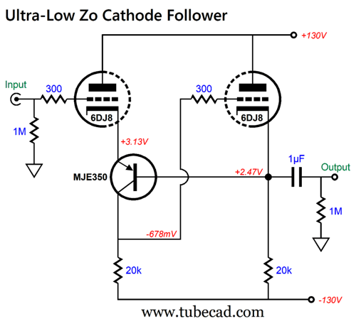
Ultra-Low Output impedance Cathode Follower
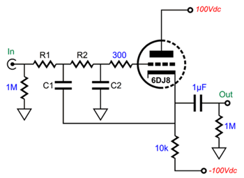
The tube equivalent looks like this:
Even with the relatively high idle current flow of 10mA, the 6DJ8's output impedance is about 100 ohms. Even if we replace the 10k cathode resistor with a 10mA constant-current source, the gain can be no higher than mu/(mu + 1) or about 0.97. Both these failings make for poor active crossovers. Note that I didn't say active filters. If you need to implement a high-pass rumble filter, then the cathode follower will work just fine. Conversely, if you are making an electronic crossover that needs to blend the loudspeaker drivers' sound outputs into a coherent and flat frequency response, then the OpAmp beats the cathode follower easily. On the other hand, what if we supercharged the humble cathode follower?
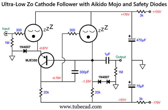
Two triodes and one PNP transistor are needed. The triode on the right is a cathode follower, while the left triode forms a bastode (inverted cascode) with the PNP transistor, which also delivers 100% of the cathode follower's output to the input triode's cathode. In other words, negative feedback. If the output is forced positive, the input triode's grid will become more negative relative to its cathode, thereby reducing the input triode's current conduction and, in turn, reducing the voltage drop across the 20k collector resistor, which further in turn will force a drop in the cathode follower's grid voltage. In other words, this hybrid buffer will buck that positive voltage increase at the output. A negative pulse applied to the output will provoke the opposite reaction, with the input triode drawing more current, thereby creating a positive pulse on the cathode follower's grid in opposition to the negative pulse. In SPICE simulations this hybrid buffer works beautifully. Reality is a different story. At startup, when neither triode is conducting yet, the two 20k resistors and the PNP transistor will be stuck at the negative rail. Not good. The workaround is to add some safety diodes.
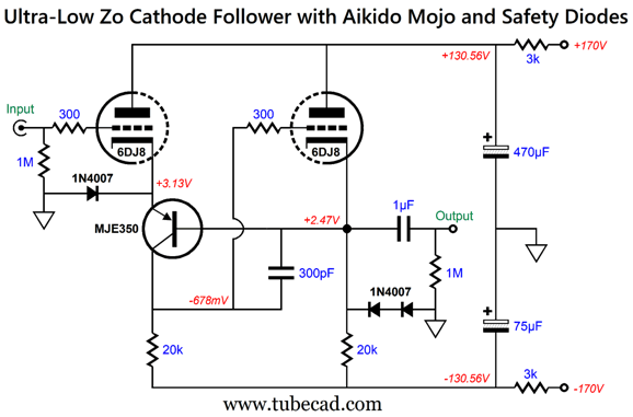
Okay, I snuck in a bit more than safety diodes. The dissimilar RC capacitors, 470µ and 75µF, provide some Aikido Mojo to improve the PSRR. The 300pF capacitor prevent high-frequency peaking. To see how well the diode works, let's remove the triodes.
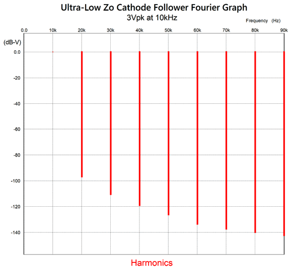
The cold triodes are safe from cathode stripping due to extremely positive grids with cold cathodes. The downside to the diodes is that they will limit the maximum output voltage swing to about ±4Vpk, which is no big deal in an active crossover, as 2Vpk is enough to bring most power amplifiers to full output. If it proves to be a big deal, we can place more diodes series or use two low-voltage zener diodes in opposition. The distortion is plenty low, coming in at close to 0.001% in SPICE simulations:
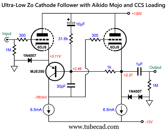
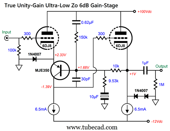
The output impedance is crazy low, as in less than one ohm! (Only 0.6 ohms in SPICE simulations.) The gain, on the other hand, still doesn't reach true unity-gain, i.e. 1:1, as it comes in at 1:0.963. What to do? We can replace the 20k resistors with 5mA constant-current sources, but that only raise the gain to 0.968; and the PSRR slightly worsens, going from -31.7dB at 100Hz to -30dB (this is without the RC filters). At the same time, the constant-current sources allows us to use a vastly lower negative power-supply rail voltage, say just -12Vdc, which could also be used to power the tube heaters. The workaround is to inject some Aikido Mojo.
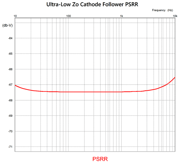
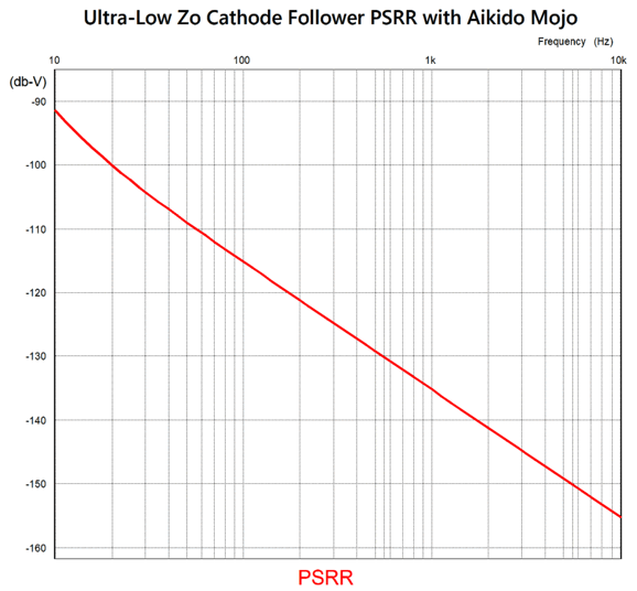
Note that the high-frequency capacitor is now only 30pF, not the old 300pF. Also note that the B+ voltage was lowered to 100Vdc and the constant-current sources are now 6.5mA. The 31.6k Aikido Mojo resistor is mu (amplification factor) times greater than the 1k resistor. Here is the improvement in PSRR:
Add a simple RC filter (3k and 300µF) to the B+ voltage and the PSRR improve by another -60dB at 100Hz.
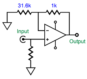
Excellent, but we still have the problem of not reaching true unity-gain. Or do we? The Aikido Mojo technique also produced a wee bit of gain, bringing the final gain to 0.9994, close enough for making an active crossover. If we pause to think about it, this makes perfect sense, as the PNP transistor's base is effectively the buffer's inverting input, so we have the equivalent to an OpAmp amplifier, whose gain is equal to 3.16k/(3.16k + 1k).
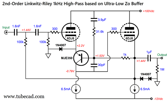
That the inclusion of the Aikido-Mojo parts ended up achieving the two goals, enhanced PSRR and true unity-gain, tickles me greatly; I didn't plan on it, but I am happy to take credit for it nonetheless. Next, we put this fancy hybrid buffer to use in an active crossover. To be honest, if a 1st-order crossover is needed, then we can use the textbook cathode follower—unless we also need an ultralow output impedance to drive the power amplifiers, in this case the fancy buffer would be the best choice. Second-order loudspeaker crossovers most often are (and should always be) of the Linkwitz-Riley alignment, which has both driver down -6dB at the crossover frequency and the drivers wired out of phase to each other. The Linkwitz-Riley crossover acoustically sums to flat, whereas the Butterworth alignment crossover, when summed acoustically, peaks +3dB at the crossover frequency. The math is super easy: C = 159155/R/Fcrv or R = 159155/C/Fcrv Where C is in µF. Here is a design example, a 2nd-order 1kHz high-pass filter in the Linkwitz-Riley alignment:
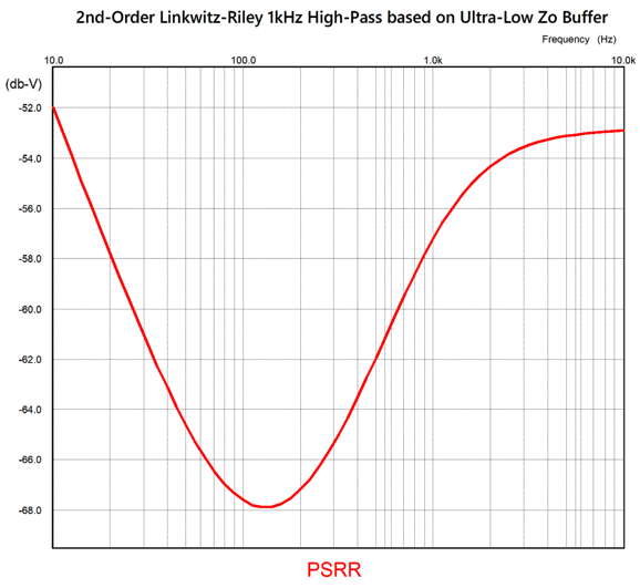
The actual capacitor value should be 1.59155nF, so the 1.6nF capacitor is 0.5% too high in value, which means that the actual crossover frequency will be 994.7Hz. The horror! On the other hand, loudspeaker drivers are anything but flat in output. In other words, do not fall into the trap of overly-precise part values. The fact is that 1.6nF is not only good enough for government work; it's good enough for super-high-end audio work. Moreover, the bigger problem is finding super-tight tolerance capacitors made from audio-pleasing materials. Often, we must settle for 3% tolerance polypropylene capacitors. One additional problem is that even if we could find a 0.01% 1.59155nF capacitor, it would not exhibit 1.59155nF of capacitance after being soldered, as the high heat will have deformed the capacitor's physical structure. In SPICE simulations, the raw PSRR was excellent.
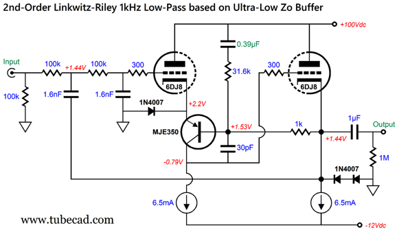
Okay, now we move on to the low-pass-filter complement.
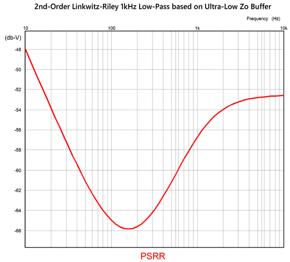
Note that the Aikido-Mojo capacitor is now only 0.39µF. Why? The buffer's input no longer attaches directly to ground; instead, the grid sees capacitors and resistors. In SPICE simulations, this capacitor value produced the following PSRR graph.
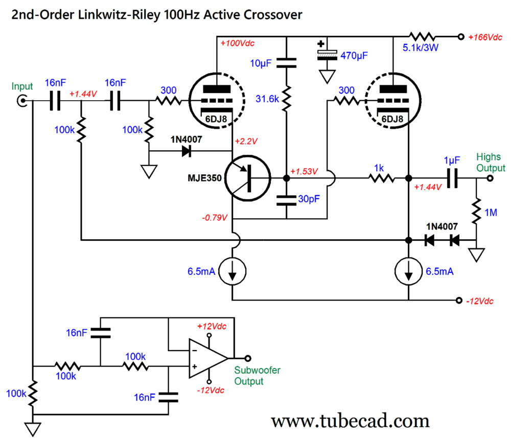
Rectifiers create a ripple frequency of either 100Hz or 120Hz, depending on where you live, so we want to PSRR dip to center at 100Hz to 200Hz. Bear in mind that this is the raw PSRRR, without any RC filtering or regulation. The question you should be asking yourself is, how well does the 0.39µF capacitor work with a crossover frequency of 100Hz? I just ran the SPICE simulations, and the optimal capacitor value turned out to be ten time bigger, i.e. 3.9µF. This is good to know, as we can generalize to the formula: C = 390µF/Fcrv Mind you, this only works with the 6DJ8. Of course, if we add an RC filter to the B+ voltage or employ high-voltage regulation, the PSRR can only improve. Of course, we can go farther down the hybrid path, as we can use the tube-based buffer for the high-pass filter and an OpAmp for the low-pass filter.
Since the tube-based buffer requires a -12Vdc power-supply rail, it would be no big deal to add a +12Vdc power-supply rail. By the way, the subwoofer must be wired out of phase relative to the main loudspeaker.
3rd-Order Crossovers
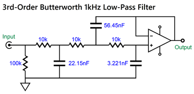
This hybrid buffer works beautifully with the textbook 3rd-order active filter designs in SPICE, but in SPICE we can specify any capacitor and resistor values we want. Sadly, in reality, we are stuck with those values we can buy. Of course, you can place these parts in parallel or in series, thereby creating the missing values, but that is a hassle, which is only made worse if you are inclined to buy $80 fancy boutique 0.01µF capacitors. Do you really want to place two in series to get 0.005µF of capacitance? Actually, the high-pass filter can use all the same capacitor values, while the resistor values vary wildly, which is okay as resistors are made in the E192 standard and with 0.1% tolerance. It's the textbook 3rd-order low-pass filter that requires crazy and differing capacitor values.
True, it doesn't look that bad, as we can buy 22nF, 56nF, and 3.3nF capacitors, which are al close to the target values. But at other crossover frequencies, such as 800Hz, only one readily-available capacitor value (27nF) comes close. I went to the Mouser website and put in place a database filter of "1%" and "polypropylene" and "not surface-mounted." Here are the values of capacitors that were available afterwards:
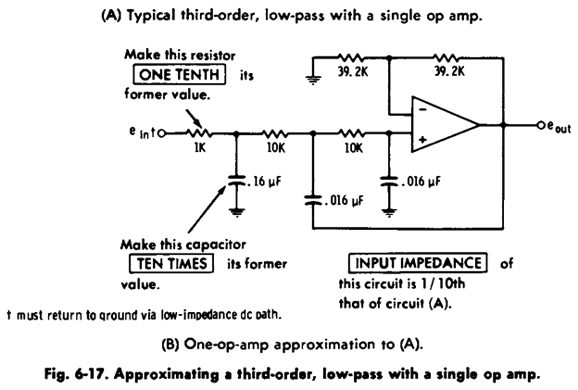
Note the gaps, for example where are the 240pF and 300pF capacitors? Mind you, I didn't add to the database filter the additional requirement that the capacitor actually being in stock, which would have truncated the list even further. The late and great Don Lancaster offered a solution to the paucity of tight-tolerance capacitor values in his book, Active Filter Cookbook. (Be sure to follow the link to the book, as it leads to a free downloadable eBook from Don's website.) His solution uses two capacitors of the same value along with one capacitor a decade bigger in value.
Note that the OpAmp deliver a gain of 1:2 or +6dB, which was set by the two negative feedback resistors being equal in value. Don's design has a 2nd-order low-pass filter with a Q of 1 preceded by a 1st-order low-pass filter with a Q of 0.707, resulting in a combined Q of 0.707, as Q are multiplied against each other. Can we do the same with the hybrid buffer? Yep.
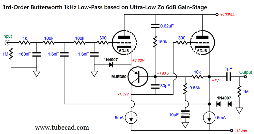
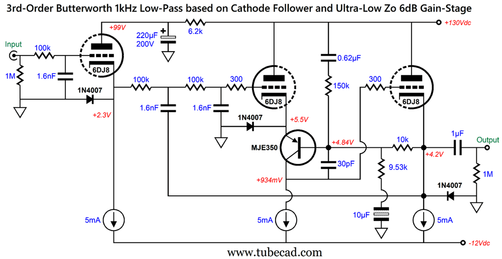
The 9.53k and 10k resistors produce a gain of two (1:2), while the 150k resistor and 0.62µF capacitor provide the Aikido Mojo needed for an enhanced PSRR. By the way, this circuit might make an excellent line-stage amplifier, as most modern signal sources, such as CD players, DACs, streamers… deliver at least 1Vpk of output signal, which when doubled is enough to drive most power amplifiers to full output. Just put two of these circuits in a fancy, heavy enclosure that is adorned with a thick faceplate, as every extra tenth of an inch raises the price by $1k, and big metal knobs and fancy gold RCA jacks and slap an $8,000 to $12,000 price tag on it and you are set for early retirement. Here is a design example of a 3rd-order 1kHz low-pass filter:
By the way, there is no absolute need to use the high-voltage MJE350 PNP transistor; I just own a bunch and I like them. Note that I didn't follow Lancaster's 1/10th rule, as the first resistor (1k) is 1/100th the value of the following resistors. Why? His trick resulted in a 0.7dB dip in the combined output at the crossover frequency. Remember, active crossovers have more stringent demands than do single filters. Let's say you need a 500Hz crossover; all you need to do is increase all three filter resistor values by two. The formula would be: R' = R·1000/Fcrv or use R = 1591.55/C/Fcrv for the first resistor, R = 159155/C/Fcrv for the following two resistors For example, if the crossover frequency is 300Hz, we get 3.3k, 330k, and 330k; if 2kHz, 499, 49.9k, and 49.9k, as they do not make 500-ohm and 50k resistors. Some signal sources might balk at the low resistor and capacitor values that result from applying the 1/100th ratio. One workaround would be to add a cathode follower to the mix.
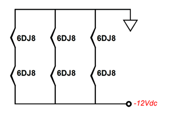
No Aikido Mojo can be applied to the cathode follower (other than modulating is constant-current source to produce an anti-phase conduction to the power-supply noise, which I have done). Thus, we use a simple RC filter on its plate. Now, all the filter resistors and capacitors share the same value. Note that the rightmost 6DJ8 now only gets one safety diode, as this triode's cathode voltage is sufficiently high to only need one diode. In other words, the cathode follower input stage limits the maximum voltage output swing to about 3Vpk, while the hybrid buffer's mx output voltage swing is closer to ±5Vpk. We will need three 6DJ8 tubes for a single channel two-way crossover, which isn't too extravagant. As I have mentioned prior, we can use the -12Vdc power-supply rail to also power the tube heaters, as two heater elements can be place in series. With a total of six tubes in a stereo two-way crossover, we would have three two-heater strings in parallel.
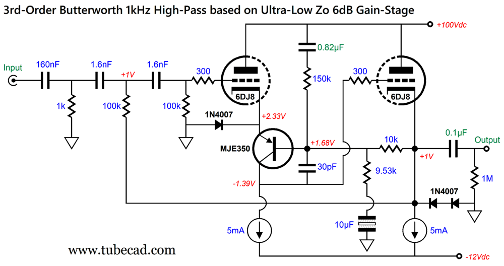
Next, we look at the high-pass filter complement.
Note the changes in capacitor values within the buffer, 0.82µF and 0.1µF. Why? The first capacitor change better centered the PSRR null at 120Hz, and the second change dealt with the issue of not needing low-frequency bandwidth with the high-pass filter. Of course, if your tweeter power amplifier presents a 10k input impedance (or lower), use a much bigger-valued output coupling capacitor.
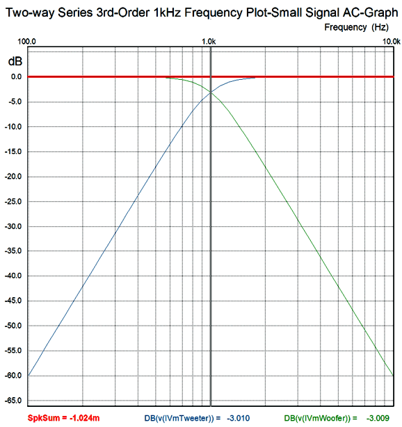
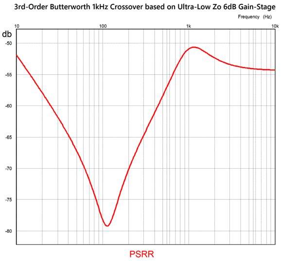
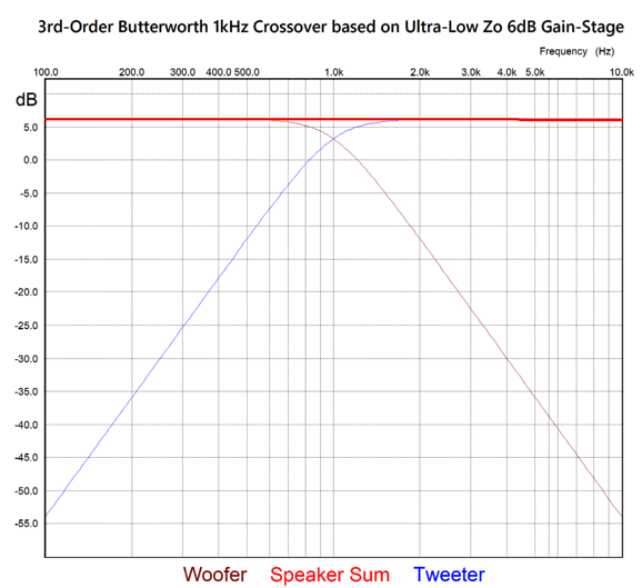
Once again, this is the raw PSRR without any power-supply filtering. I wondered how well this active 3rd-order crossover behaved in loudspeaker summation. Very well indeed. The resulting summation:
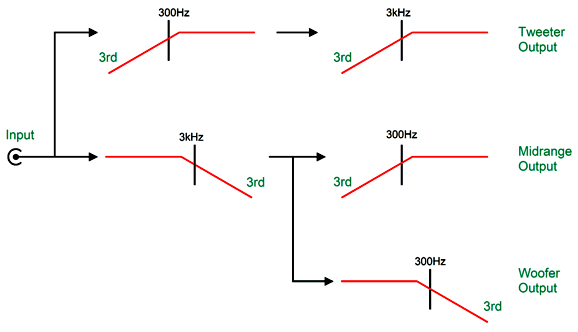
Note that the loudspeaker summation is not at 0dB but at +6dB due to the buffers delivering a gain of +6dB. This boost in gain might prove an advantage in a system where the signal source, say a DAC or streamer, lacks sufficient output voltage swing to drive the power amplifiers to full output. In other words, this active crossover would also work as a line-stage amplifier. Also note that we must include the +6dB of signal gain in a comparison of this graph to the one at the beginning of this section, which shows the woofer and tweeter outputs being -60dB down at one decade away from the crossover frequency. Subtract the 6dB of gain from the plotlines above, and we get the same -60dB of attenuation one decade away from the crossover frequency. What about three-way active 3rd-order crossovers? Do not think about cascading 3rd-order filters without first reading my Post 539, which explains how to avoid a big trap in 3rd-order designs. Here is an example of a passive crossover flowchart from the post.
This is what the active three-way arrangement should look like, with the woofer and the tweeter seeing cascading crossover frequencies, creating two-slope cutoffs, the midrange only single slopes.
4th-Order Crossovers
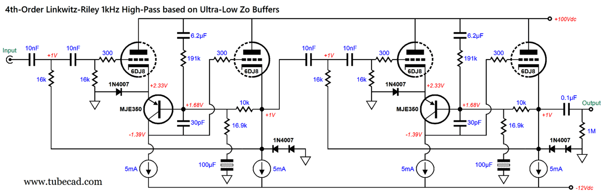
This crossover provides huge midrange and tweeter protection, as being -80dB per decade is a huge amount of attenuation. In contrast, the 1st-order is only 20dB down, which translates into getting 1/10th of the signal, while -80dB translate into getting 1/10,000th of the signal. In order to get away with using the same capacitors values throughout, the buffer must deliver gain. How much? Less than the 3rd-order crossover require, only 1:1.5858. This will require juggling the buffer's part values, so I have done the hard work for you.
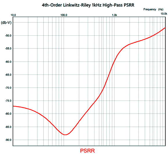
Two hybrid buffer/amplifier stages are needed. The same filter capacitor and resistor values are used throughout. It took some effort to create the deepest PSRR null centered at 100Hz.
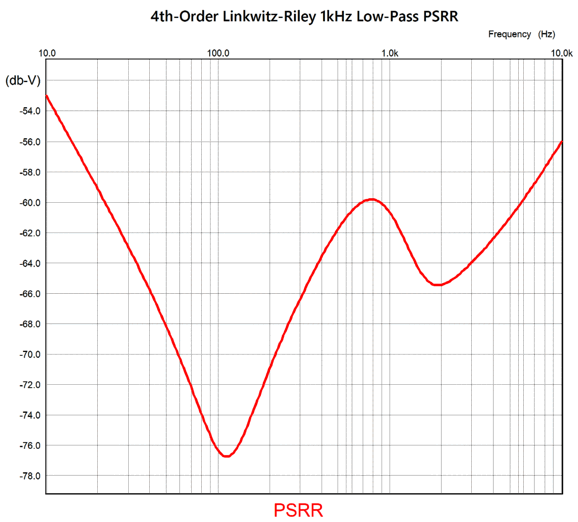
That is excellent raw PSRR for the high-pass filter. Add some passive filtering or regulation to the B+ voltage and the PSRR improves even more. The low-pass filter lagged a bit behind.
Once again, the required math for setting the crossover frequency is super easy: C = 159155/R/Fcrv or R = 159155/C/Fcrv Where C is in µF.
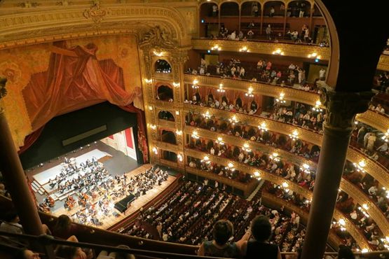
Music Recommendation: Recently, one of my favorite podcasts, EconTalk, with Russ Roberts, and which covers far more than just economics, asked the following questions: "How can opera, with words we rarely understand, make us cry? Why does opera, filled with melodrama, move us?" Questions that the poet and librettist, Dana Gioia, answered so well that I might have to rethink my opera hesitancy.
Here's the link to the YouTube video of the podcast. Listen or view at your own risk. //JRB
Did you enjoy my post? Do you want to see me make it to post 1,000? If so, think about supporting me at Patreon.
User Guides for GlassWare Software
For those of you who still have old computers running Windows XP (32-bit) or any other Windows 32-bit OS, I have setup the download availability of my old old standards: Tube CAD, SE Amp CAD, and Audio Gadgets. The downloads are at the GlassWare-Yahoo store and the price is only $9.95 for each program. So many have asked that I had to do it. WARNING: THESE THREE PROGRAMS WILL NOT RUN UNDER VISTA 64-Bit or WINDOWS 7, 8, and 10 if the OS is not 32-bit or if it is a 64-bit OS. I do plan on remaking all of these programs into 64-bit versions, but it will be a huge ordeal, as programming requires vast chunks of noise-free time, something very rare with children running about. Ideally, I would love to come out with versions that run on iPads and Android-OS tablets.
|
I know that some readers wish to avoid Patreon, so here is a PayPal button instead. Thanks.
John Broskie
John Gives
Special Thanks to the Special 89 To all my patrons, all 89 of them, thank you all again. I want to especially thank
I am truly stunned and appreciative of their support. In addition I want to thank the following patrons:
All of your support makes a big difference. I would love to arrive at the point where creating my posts was my top priority of the day, not something that I have to steal time from other obligations to do. The more support I get, the higher up these posts move up in deserving attention.
If you have been reading my posts, you know that my lifetime goal is reaching post number one thousand. I have 384 more to go. My second goal was to gather 1,000 patrons. Well, that no longer seems possible to me, so I will shoot for a mighty 100 instead. Thus, I have just 11 patrons to go. Help me get there. Thanks.
New URL of the GlassWare website |
|||||||||||||||||||||||||||||||||||||


| www.tubecad.com Copyright © 1999-2025 GlassWare All Rights Reserved |