| John Broskie's Guide to Tube Circuit Analysis & Design |
| February 02 2025 | Post Number 615 |
||||
Improved Crossover Design
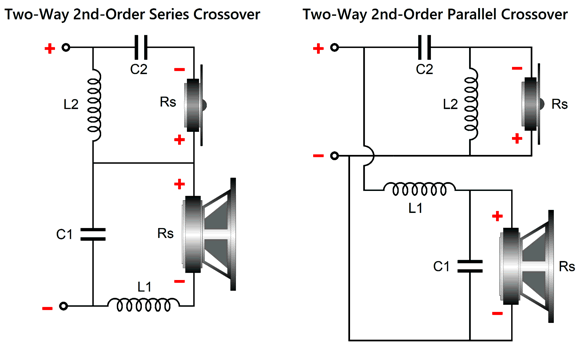
The parallel topology is what most audio practitioners know and what most loudspeaker enclosures contain. (If your speaker offers bi-wire connections, it certainly holds a parallel crossover.) Both topologies deliver the same results in SPICE simulations, where the loudspeaker drivers are conveniently and confidently replaced by 8-ohm resistors. Real loudspeaker drivers, alas, are nothing like 8-ohm resistors, being instead complicated mechanical-electrodynamic devices. For example, with the exception of planar electrodynamic drivers, few loudspeaker drivers actual deliver a DCR of 8 ohms, delivering instead a rollercoaster plotline of impedance versus frequency. Does this matter? Indeed, it does. From my Post 481, this in turn quotes my Post 402:
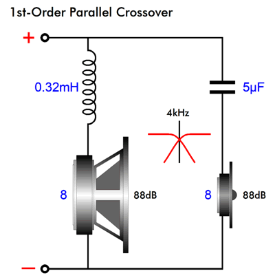
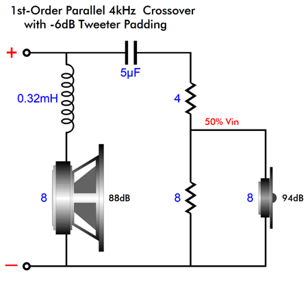
I have covered the problem of tweeter resonance in my Post 590, in the section titled "Important Caveat About Fs." Here SPICE simulations do prove useful. Let's start with a simple 1st-order parallel 4kHz crossover.
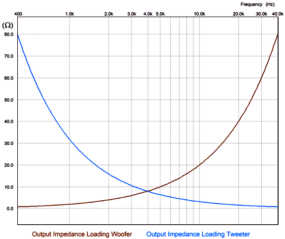
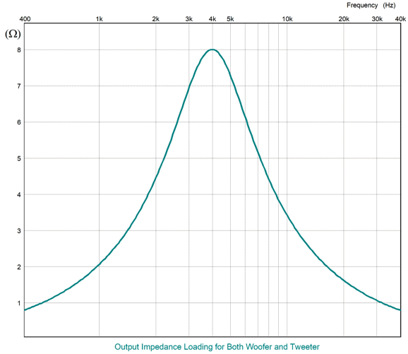
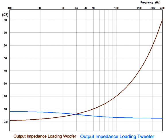
We use the same capacitor and inductor values to make a series crossover, which will perform in a perfectly-equal fashion in SPICE simulation with resistors replacing real loudspeaker drivers. The problem is those resistors do not care what the source impedance is of the electronic device powering them. A resistor experiences the same voltage drop and dissipation no matter what the source impedance is. Here is the SPICE-generated impedance plotlines created by the parallel crossover topology.
At the crossover frequency, both the woofer and tweeter see the same 8-ohm source impedance (assuming vanishingly-small output impedance from the power amplifier). At DC, the tweeter sees an infinitely-high source impedance, while the woofer sees zero ohms of impedance, but infinitely high frequencies it, too, sees an infinitely-high source impedance. Consider this: what if much of the sonic benefit resulting bi-amping results not from doing away with the passive crossover part imperfections, but their source impedance, as a good power amplifier delivers both a low and flat output impedance across the audio bandwidth. Let's compare the previous graph to the following graph for the series crossover.
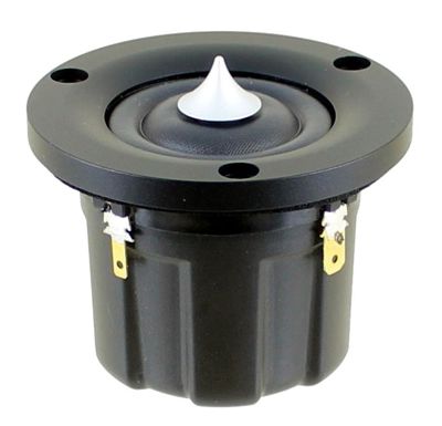
Once again, at the crossover frequency and only at the crossover frequency, both the woofer and tweeter see the same 8-ohm source impedance. At DC, the tweeter and woofer both see zero ohms of impedance, while at infinitely high frequencies both see the same zero-ohm source impedance. Does this matter? Oh yes, indeed it does. For example, the highly esteemed dome tweeter from Scan-Speak, the R3004/602200 Illuminator Ring Radiator Tweeter, exhibits a resonant frequency of 430Hz, with a mechanical Q (Qms) of 2.3, an electrical Q (Qes) of 0.48, and a total Q (Qts) of 0.4, which is derived from placing the Qms in parallel with the Qes.
With the parallel crossover presenting an impedance of 78 ohms at 430Hz, the tweeter's Qes rises to 12.96, while its Qts climbs to 1.88. Now, a Qts of 0.4 is nicely damped, but a Qts of 2.3 is exuberantly peaky, as it represents a peaking of 5.5dB. Let's compare this to the series crossover. It presents an impedance of 0.9 ohms at 430 Hz, which will cause the tweeter's Qes to rise to 0.62, and its Qts to rise to 0.49. (Critically damped is at a Q of 0.5.) Which do you think would sound better? Here is another question: what's the point of having a power amplifier that delivers a damping factor of 400, when the crossover presents an impedance of 78 ohms at the tweeter's resonant frequency? So far, the assumption has been that the woofer and tweeter share the same SPL sensitivity at 2.83V/Meter. Usually, woofers lag far behind midranges and tweeters; thus the need for L-pads to reduce the output from the higher-SPL drivers to match that of the low-efficiency woofer.
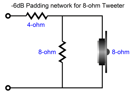
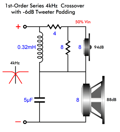
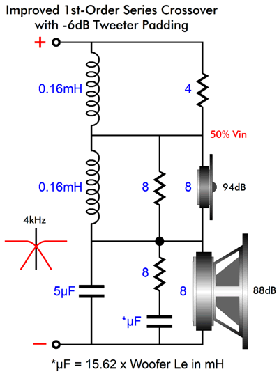
This example cuts the input voltage the tweeter in half, which results in a -6dB reduction in its SPL. As far as the crossover is concerned, the load is still 8 ohms. As far as the tweeter is concerned, the lowest source impedance it can ever see is 2.66… ohms, as 8 in parallel with 4 equals 2.666… Let's add this L-pad to the parallel crossover.
The woofer and tweeter now deliver the same SPL. The source-impedance plotlines look different now.
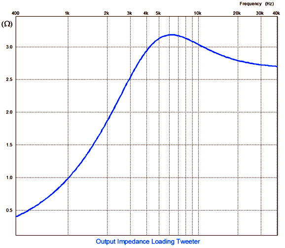
The tweeter now sees a high of 8 ohms and a low of 4 ohms. Certainly for the tweeter at resonance, 8-ohms is far better than 78 ohms, so we see the L-pad actually doing more than just attenuating. Next, we add the L-pad circuit to the series crossover.
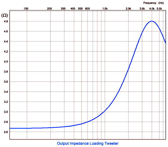
The resulting source-impedance plotline proves interesting.
Peaks at 4.8 ohms, with a low of 2.666… Better but not perfect. Okay, it's now time to reveal my workaround, i.e. my fix.
2nd-Order Crossovers
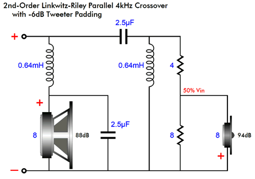
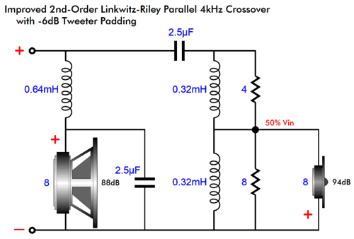
Next, we apply my fix:
Note that both L-pad resistors get shunted by inductors, with half the inductance of the previous single inductance. The 8-ohm resistor in parallel with the tweeter's 8-ohm impedance creates an impedance of 4 ohms. In other words, the top and bottom resistances match, so it makes sense that each inductor presents half the inductance. (Bear in mind that inductances add when placed in series, just like resistances. In other words, the two inductance must add up to the original single inductance.) What if the tweeter was attenuated more than -6dB, say -12dB? in this example, the top resistor would equal 6 ohms, while the bottom resistor would equal 2.666… ohms, with a 2.7-ohm resistor being close enough. The bottom 2.666-ohm resistor in parallel with the 8-ohm tweeter results in a 2-ohm resistance, making for only 25% of the input signal getting to the tweeter, thereby resulting in an attenuation of -12dB. In this setup, the top resistor would be shunted by 0.75 x 0.64mH (i.e. 4.8mH), while the bottom resistor would get an inductor equal to 0.25 x 0.64mH (i.e. 0.16mH). Note that without the L-pad resistors, the tweeter would encounter a dead short both at DC and at infinitely high frequencies. With the two resistors and two inductors, the same dead short occurs at DC; but at infinitely high frequencies, the source impedance levels out to 2.666 ohms.
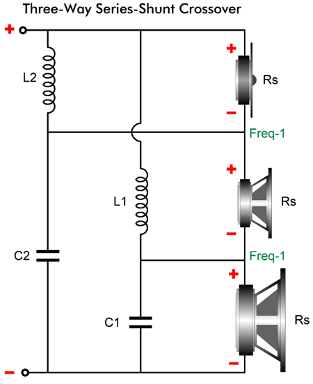
Series-Shunt Crossover
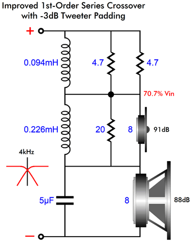
We see the same 50% attenuation of the tweeter's signal and the same equal division of the inductor values. (I added the Zobel network across the woofer, as the woofer voicecoil's inductance will trip up the crossover's functioning. Okay, now let's look at the same crossover but with a -3dB L-pad.
If you do the math, you will see that the two inductor values match the two resistances ratio. In addition, 0.094mH added to 0.226mH equals 0.32mH. Basically, wherever we find a tweeter shunted by an inductor and attenuated by an L-pad, we can apply my fix; for example, the series-shunt crossover topology.
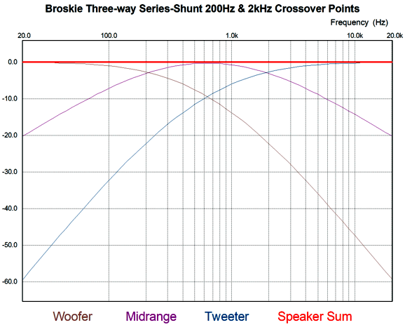
Like the 1st-order crossover, this topology offers a flat frequency response with a voltage-out power amplifier (which 99.9999% of amplifiers are) and a flat phase. It differs, however, in exhibiting a slight dip in impedance in the mid frequencies. Unlike the 1st-order three-way, which can deliver either a cascaded woofer or a tweeter cut-off slopes but not both at once, this topology produces the cascaded slopes for both the woofer and tweeter. In other words, the woofer and tweeter slopes start off as -6dB per octave and then increase to -12dB per octave, which offers greater protection for the delicate tweeter voicecoil and gets the sluggish woofer out the way before it can muddy up the midrange.
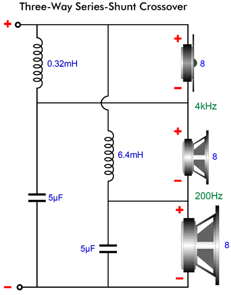
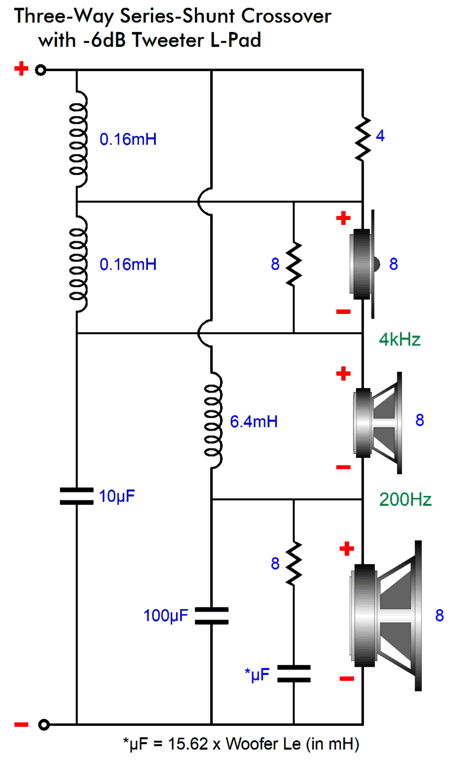
Next, ere is a design example with 200Hz and 4kHz crossover frequencies. Note that the tweeter is shunted by an inductor, which means that if the tweeter needs an L-pad, we can the two-inductor fix.
Once again, a -6dB L-pad is shown, just to make the math easier.
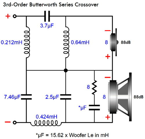
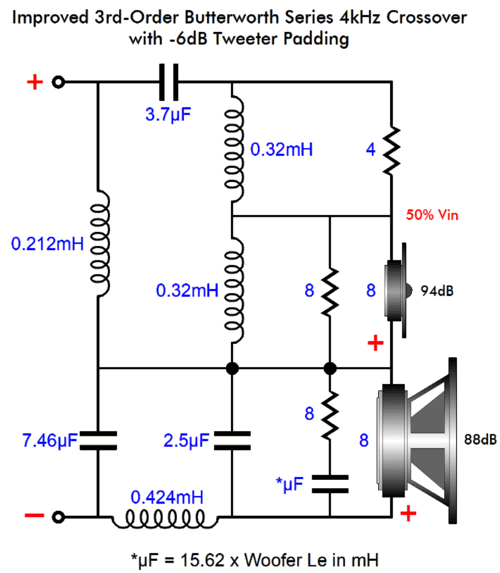
3rd-Order Crossovers
We will add a -6dB L-pad and two-inductor fix.
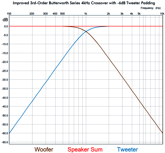
Just to make sure that this setup actually works, I ran the circuit in SPICE simulations and got this result:
Textbook perfect. What about 4th-order crossovers?
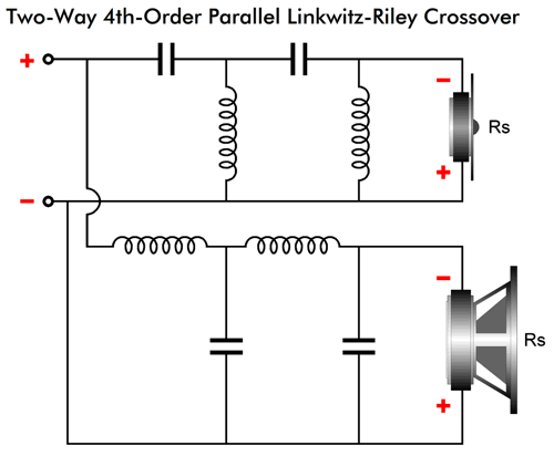
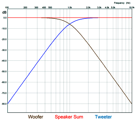
4th-Order Crossovers
Like the 2nd-order Linkwitz-Riley parallel topology, the 4th-order Linkwitz-Riley parallel crossover puts both drivers -6dB down at the crossover frequency; but unlike the 2nd-order, the 4th-order Linkwitz-Riley parallel crossover requires that both woofer and tweeter are wired in phase to each other. The 4th-order slopes are steep and offer extreme tweeter protection. I once heard a homemade loudspeaker that used this crossover with a 7-inch woofer and 1-inch dome tweeter that sounded amazing—in spite of playing inside a huge room at high SPLs. (If I remember correctly, the crossover frequency was 2.2kHz. far below the usual 3kHz crossover frequency.)
To be down -80dB one decade away from the crossover frequency means an attenuation of 1/10000. For example, a 100W power amplifier puts out 40Vpk into an 8-ohm load, so -80dB attenuation equals 4mVpk of signal. In contrast, the 1st-order yields only -20dB of attenuation; thus, 4Vpk of signal; the 2nd-order, 0.4Vpk; the 3rd-order, 40mVpk.
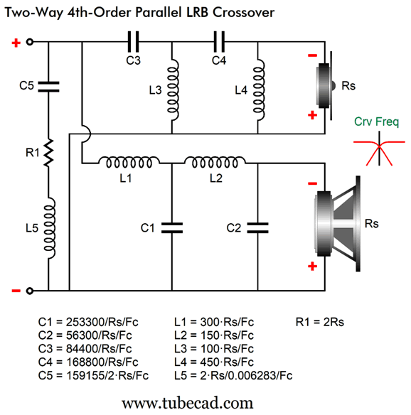
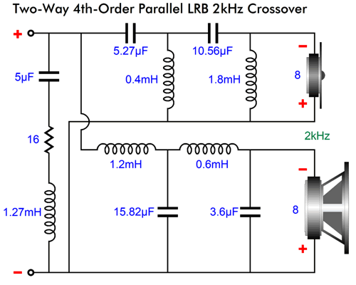
Parts C5, L5, and R1 are my contributions to flatten the impedance plotline, which would otherwise spike up at the crossover frequency. Here is a design example at 2kHz.
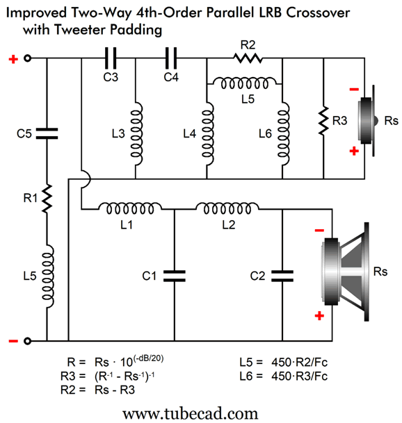
Adding an L-pad two-inductor fix is easy.
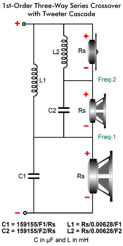
Capacitor L-Pad Fix Midranges, on the other hand, present much less voicecoil inductance (ribbon and planar midranges usually present next to zero inductance) and often deliver higher SPL than the woofer. In other words, they do get L-pads, so we can apply my two-capacitor fix. Here is a three-way 1st-order crossover that I truly like, as the crossover's tweeter cascading slopes offer greater protection and still delivers a flat phase response. In other words, a square wave goes in and a square wave comes out—well, it comes out more like a square wave than 2nd-order or 3rd-order or 4th-order crossovers can ever hope to produce.
The required math is mercifully easy.
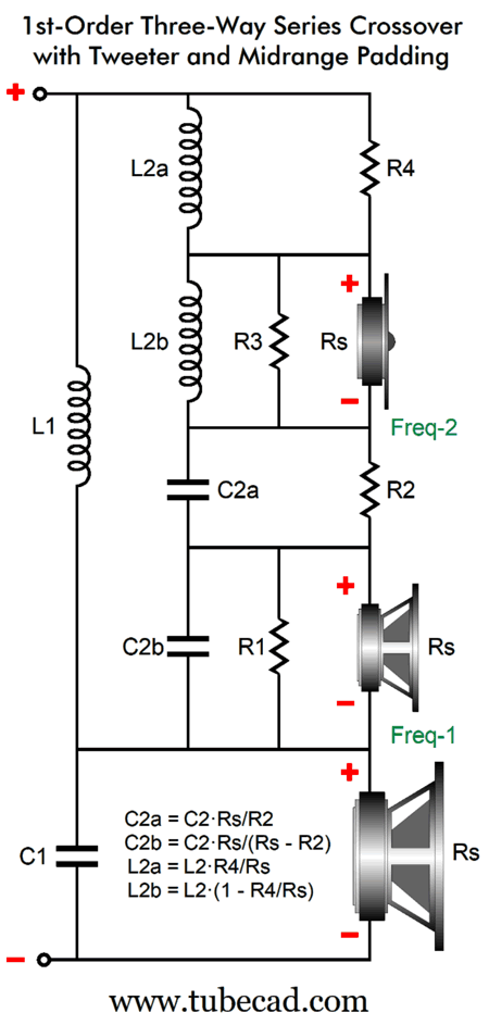
Both the midrange and tweeter get L-pads, which can differ in attenuation. A typical SPL disparity is along the lines of the tweeter delivering 96dB, the midrange 91dB, and the woofer lagging behind at 88dB. Note that the single capacitor shunting the midrange has been replaced by two capacitors. Capacitors, unlike inductors and resistors, do not add in series; instead, like resistances in parallel, they subtract. For example, two 20µF capacitors in series yield only 10µF of capacitance. In other words, expect to use bigger capacitor values. I began this section by quoting my earlier post, so I will end it by also quoting a previous post:
Often, I have been asked just what the whole point is behind my many, many posts. My answer is simply that I hope raise the general level of audio equipment. At the same time, I wanted to write and create content that be something that I would want to read and see--even if, and especially, if it weren't mine. Well, this post will at first be largely ignored, but in about ten years I expect that my L-pad fix will simply be established practice in the making of loudspeaker crossovers. Okay, I take that last sentence back. That's not how things work in the loudspeaker industry. Crossovers are designed in Crossover Software, just as the enclosure volume and port diameter and length are designed dictated by Speaker-Enclosure Software. Following the prescribed decisions of software is not only easy, it is safe. Safe in that if things do not turn out well, you are exempt from blame, as you were only following digital orders. When Vance Dickason releases his 15th Edition of The Loudspeaker Design Cookbook with my crossover fixes, the creators of crossover software will incorporate them the code.
Music Recommendation: Lucinda Williams' Tetralogy
If you are under the age of sixty, you probably cannot understand how the culture and minds were heavily influenced by The Beatles. Each new song from the (original) Fab Four hit the earth like a meteor large enough to level London. Throughout the day, you would be asked, "Did you hear it?" To a lesser extent, the same holds true for The Rolling Stones, Bob Dylan; and to a much, much lesser extent, Tom Petty in the late 1980s. A singer must bring something special to a cover album of these treasured standards, something new and revelatory. Williams does. //JRB
Did you enjoy my post? Do you want to see me make it to post 1,000? If so, think about supporting me at Patreon.
User Guides for GlassWare Software
For those of you who still have old computers running Windows XP (32-bit) or any other Windows 32-bit OS, I have setup the download availability of my old old standards: Tube CAD, SE Amp CAD, and Audio Gadgets. The downloads are at the GlassWare-Yahoo store and the price is only $9.95 for each program. So many have asked that I had to do it. WARNING: THESE THREE PROGRAMS WILL NOT RUN UNDER VISTA 64-Bit or WINDOWS 7, 8, and 10 if the OS is not 32-bit or if it is a 64-bit OS. I do plan on remaking all of these programs into 64-bit versions, but it will be a huge ordeal, as programming requires vast chunks of noise-free time, something very rare with children running about. Ideally, I would love to come out with versions that run on iPads and Android-OS tablets.
|
I know that some readers wish to avoid Patreon, so here is a PayPal button instead. Thanks.
John Broskie
John Gives
Special Thanks to the Special 89 To all my patrons, all 90 of them, thank you all again. I want to especially thank
I am truly stunned and appreciative of their support. In addition I want to thank the following patrons:
All of your support makes a big difference. I would love to arrive at the point where creating my posts was my top priority of the day, not something that I have to steal time from other obligations to do. The more support I get, the higher up these posts move up in deserving attention.
If you have been reading my posts, you know that my lifetime goal is reaching post number one thousand. I have 393 more to go. My second goal was to gather 1,000 patrons. Well, that no longer seems possible to me, so I will shoot for a mighty 100 instead. Thus, I have just 8 patrons to go. Help me get there. Thanks.
New URL of the GlassWare website |
||||


| www.tubecad.com Copyright © 1999-2025 GlassWare All Rights Reserved |