| John Broskie's Guide to Tube Circuit Analysis & Design |
| January 01 2025 | Post Number 614 |
||||
Happy New Year!
With re-clocking and de-jittering, CDs sound great, sounding much like LPs, but without the ticks and pops and warps and truncated dynamic range… Sadly, most audiophiles and all non-audiophiles know nothing about re-clocking and de-jittering of digital signals. Why not? The audio world overstuffs with putatively sonic breakthroughs, such as a new silk interlaced power cords or rare-earth equipment feet that escalates your system to intoxicating new heights. I have been trying to convince an old friend to try re-clocking and de-jittering, but with no success. His view is that digital sucks, and that is the end of the story. I try to explain that re-clocking and de-jittering does not alter the frequency response or the tonality of digital audio, but rather the texture, the sonic focus. He cannot hear me; it's as if I had tried to convince him that Taco Bell now produces the best Mexican food in America. His decades of experience argue more persuasively. So sad. Just a few seconds of listening would win him over. One instantly perceived improvement is the apparent drop in noise and volume, but with the SPL meter showing no difference in sound level. A paradox, which is resolved by realizing that we associate high SPL with high distortion; subtract the distortion, and the SPL seemingly falls. (I am not talking about the static distortion analyzer readout of sine-wave THD, but dynamic distortion that only the ear can evaluate.) A tiresome phrase, which I have been abundantly guilty of using, is "Why didn't the dog bark?" The question audiophiles should ask instead is, Why aren't there any dogs? Or, rather, Why aren't there any puppies? Audiophiles near their expiration date. Soon, mortuaries and cemeteries will purchase Stereophile and The Absolute Sound's subscriber lists as they seek future customers. In other words, why are there so few young audiophiles? No doubt, much of their absence is explained by stupidly expensive audio gear. Given the choice between buying a new iPhone or an entry-level audio-grade power cord, the wise youngster chooses the new phone. (The few young, budding audiophiles I have met, which includes my 19-year old daughter, buy LPs.) The remainder can be explained by modern audio, i.e. digital audio, not being all that compelling. With re-clocking and de-jittering, digital compels. Alas, it takes time for lightning to be heard.
MORE
2-Driver DAH Subwoofer The something new is a power DAC. Usually, audio DACs are housed in small IC packages much smaller than your fingernail and typically come in 16-, 24-, or 32-bit resolutions. In addition, they put out very little peak current and voltage; usually, ± 1mA or ± 2.2V, depending on whether the DAC is a current-out or a voltage-out DAC. What I have in mind is beefy 4-Bit DAC that is fashioned from power solid-state devices in TO-220 or TO-247 packages and delivers output current and voltage sufficient to drive the larger subwoofer driver to the limits of its excursion. Effectively, the power DAC is a current-output design that uses the large subwoofer driver to create an analog output signal (i.e. sound). Instead of ± 2.2V, the power DAC delivers a peak output voltage of ± 32V and peak current of ±15 A into the 15in woofer, which translates into 332W with square-wave output. (If the math seems wrong, do not worry; it will make sense.)
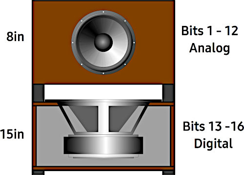
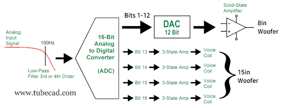
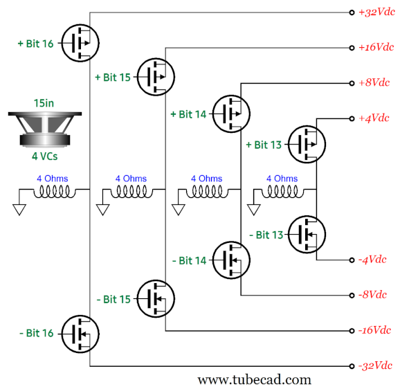
Imagine a relatively small subwoofer enclosure 18 inches square and 22 inches tall. This subwoofer contains two drivers, a 15in woofer and an 8in woofer. The analog input signal (say, 1Vpk) passes through a steep low-pass filter before entering the 16-bit ADC. The first 12 bits of lesser significance digital output are fed to the 12-bit DAC and the DAC's analog output signal feeds the 8-inch woofer's internal analog (i.e. linear) power amplifier. The power DAC gets the last four bits, the most significant bits, so the 15-in woofer may not be engaged at all at low volumes or with music with little deep-bass content. The 15-inch woofer must hold four voicecoils, not one or two, but four. Each voicecoil presents 4 ohms of impedance. Such a subwoofer woofer driver is not currently being made, but it easily could be, as the process that creates dual voicecoils is simply doubled. Each 4-ohm voicecoil is driven by its own internal 3-state power circuit, all of which attaches to a multi-voltage bipolar power supply, whose rail voltages are -32V, -16V, -8V, -4V, 0V, +4V, +8V, +16V, and +32V.
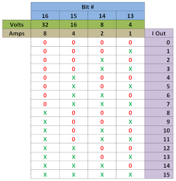
In other words, a single 15in subwoofer replaces the four woofers in my previous design from my last post. This 4-bit arrangement yields 30 states of possible woofer cone excursion, either out or in, with the 31th state of neither pumping out nor sucking in. When a MOSFET turns on, it effectively shorts the voicecoil to the power-supply rail. Each rail-terminated voicecoil compels cone excursion. With four voicecoils, we can produce 15 increments of current flow in 1A steps. The following table shows how the 15in woofer will respond to the possible on-offs.
My guess is that some readers are confused now, as they see it, a loudspeaker driver cannot obey four different masters at once. To their reckoning, if one voicecoil sees 32V while another sees 4V, the 4V engaged voicecoil will drag down the 32V voicecoil, as the 4V voicecoil wants the cone to move 4mm, while the 32V voicecoil wants 32mm of movement. (This reminds me of the old Aristotle notion that the heavier the object, the faster it falls. Thus, if you attached a tennis ball to a cannonball and dropped the pair, the lighter ball would slow down the heavier ball.) The first step to make sense of what is going on is to stop thinking primarily in voltage, but in current. It's the flow of current through the voicecoil that makes the cone move. If tomorrow superconducting wire were developed, soon we would be seeing subwoofer drivers with zero-ohm voicecoils. A speaker's resistance is just the accidental and unhappy consequence of using wire that offers resistance. The formula for the force that moves the speaker cone is:
Voltage does not enter the formula. Of course, voltage does enter our calculations due to the parasitic DC resistance (Re) that voicecoil's present. Another consideration is that the 15in woofer is not being used in the conventional way, as it must respond to DC pulses, not sine waves. In addition, it is being operated far below its in-cabinet resonance, as the relatively small sealed enclosure supplies the springiness to restore the cone to its neutral position and presents a load to the cone. With the sealed box loading, and in the compliance-dominated region below resonance, the equation for excursion roughly is: Excursion = Cms × BL × V/Re Where Cms is the driver's suspension compliance (an inverse measure of its surround and spider's restoring springiness). Trapped air in the sealed cabinet has its own compliance. Or, rather, its own lack of compliance; if the enclosure is small, the air is less compliant; if large, the air is more compliant. The cabinet's own low compliance will subtract from that of the driver. Each voicecoil's current flow will add together. An alternative arrangement would be to use eight constant-current sources, each digitally shut off or turned on, with a single voicecoil woofer.
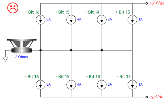
As far as the woofer is concerned, this arrangement yields the same cone movements. As far as efficiency is concerned, an unhappy face is awarded, as the constant-current sources must dissipate a lot of heat. For example, the 1A constant-current sources, will when singly engaged, produce a 2V voltage drop across the voicecoil, which will dissipate 2W, as 1A against 2V equals 2W; the "on" constant-current source will dissipate 32W, however, as it sees a 32V voltage drop. Even worse, when just the bit-16 is engaged, the constant-current source must dissipate 144W! In contrast, the MOSFET on-off switches present a low drain-source (on-state) resistance (R DS), only 180 milliohms for the old-school TO-220 IRF640 and only 6.5 milliohms for the newer Onsemi FDPF085N10A , which produces a tiny voltage drop at 8A (52mV) and, consequently, little heat dissipation. (The usual problem with power MOSFETs is their relatively high input capacitance, which makes ultrafast switching difficult. This should prove no problem in this application, as the subwoofer's high-frequency bandwidth need only extend up to 2kHz or so, well within the MOSFET's ability to quickly switch on and off.) Actually, the real hassle with MOSFET switches and multi-voltage bipolar power supply is making the bipolar power supply with multiple rail voltages. First, making any low-voltage/high-current power supply the old-fashion way is tough, as the rectifier-voltage losses become a big portion of the raw DC voltage developed. (For this reason, when it comes to low voltage-power supplies, switch-mode power supplies rule.) Nonetheless, we can go the conventional way, even with the low ±4Vdc rail voltages. We start with the following power transformer.
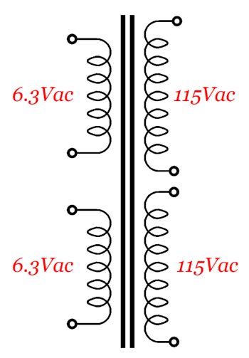
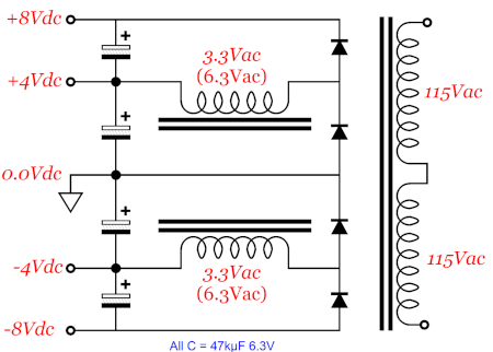
Note the dual primaries and dual secondaries. Also note the 115Vac primaries. Where I live, my wall voltage is 120; my friend's wall voltage in Northern California, 122Vac. This power transformer plugged into my wall socket yields 6.3 × 120/115 volts (6.6Vac) secondary voltages. If we place the two primaries in series, we halve the secondary voltages. If we place the two primaries in series and connect them to a 120Vac wall voltage, we get two 3.3Vac secondaries, which rectify up to 4Vdc, assuming about a 0.7V rectifier voltage drop.
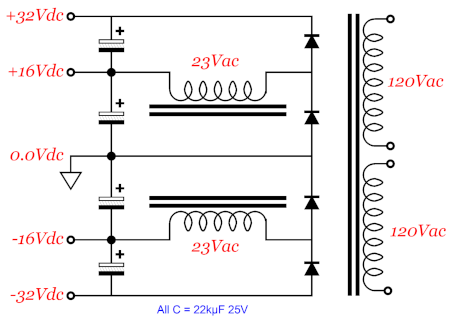
From 0V to either -8Vdc or to +8V, we have full-wave rectification; from 0V to either -4Vdc or to +4V, we have half-wave rectification. Note that the same power transformer is being used, not three inductors. To get the two higher power-supply rail voltages, we use another power transformer with higher secondary voltages, but in the same rectifier topology. The 23Vac secondaries are nominally 22Vac secondaries, but we use the same 120Vac wall-voltage trick to up the voltages, as 22 x 120/115 = 23.
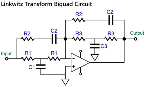
What about the linear power amplifier? How much power does it need to put out? Of course, much depends on how efficient the 8in woofer is. We do note, however, that each bit to the right halves the previous bit's output. This means that the 8-inch driver must be able to produce half the air pressure change that the 15in puts out with only the bit-13 on (in other words, 4V output into one 4-ohm voicecoil). Let's assume the 15in woofer's cone surface area is 120 square inches and that the 8in woofer is 30 square inches. We take bit-13's current output of 1A and multiply against 120, thereby getting 120 units of air displacement. This means that the 8-inch driver must be able to produce a peak output of 60 units of air displacement. Since its cone area is four times smaller, its excursion must be two times greater than the 15in's to reach half the 15in's air displacement. Assuming a similar BL factor, the 8-inch driver must see twice the 1A current flow, i.e. 2A. But as we switched from square waves to sine waves, from digital to analog, the actual peak current flow must be 1,414 times greater, bringing us to 2.828A, which an 8-ohm driver driven by a 22.6Vpk sine wave will develop. In other words, we can use the ±32V bipolar power supply rails to power the linear power amplifier. Possibly, an 8-inch woofer won't cut it, so a larger woofer will be needed. One thing that is certain is that this smaller woofer will not be able to go down to 20Hz. In contrast, the digitally driven 15in woofer can go down to DC, which may not prove to be a feature, especially if you play LPs, as warped LPs deliver subsonic bass that has no relation to the music recorded and can overload the subwoofer. As the smaller driver cannot produce an in-box resonant frequency of 20Hz, we must add the "Linkwitz Transform" biquad circuit before its internal power amplifier, which electronically alters a driver's Ftc and Qtc in a sealed enclosure, moving its Ftc down to 20Hz with a Q of 0.5.
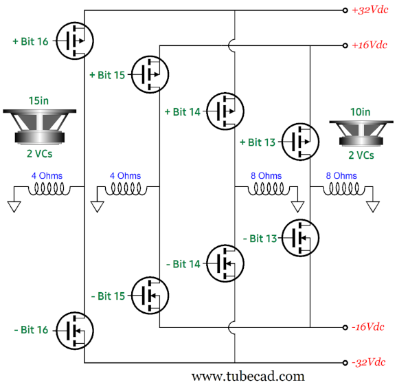
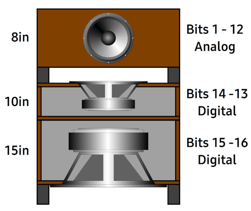
Another thing to consider is that audio DACs are usually followed by a low-pass filter that smooths away digital hash above half the sampling rate frequency. We can do the same with the four-bit power DAC by surrounding the 15in woofer's sound exits with open-cell foam or thick felt, which will impose a mechanical low-pass filter upon the emerging pulsed soundwaves. Another issue worth pondering is the nonlinearity of the trapped air in the small enclosure that houses the 15in woofer. Since it is harder to compress the air than it is too expand it, the multi-voltage bipolar power supply, whose rail voltages might have be something like -40V, -20V, -10V, -5V, 0V, +4V, +8V, +16V, and +32V. As no four-voicecoil subwoofer driver presently exists, we can still experiment with two dual-voicecoil woofers, as they are common enough. The same four-bit power DAC circuitry would be used, but twice the enclosure volume and two 15in woofers would be needed. If this test subwoofer passes our tests, then we can talk to woofer manufacturers about building a four-voicecoil subwoofer driver. Failing that, we could purposely build a DAH subwoofer that held three drivers, a 15in, 10in, and an 8in. The 15in woofer would hold two 4-ohm voicecoils, while the 10in woofer held two 8-ohm voicecoils. Neither driver is difficult to find. The 10in woofer should offer half the emitting surface area of the 15in woofer. The same four-bit resolution is used, but the bipolar power supply rail voltages have been truncated to -32V, -16V, 0V, +16V, and +32V.
When just bit-14 is switched on, the 10in woofer must produce half the air displacement that the 15in woofer delivers with just bit-15 engaged. Since the 10in woofer has half the surface area of the 15in woofer, one of its voicecoils must see the same current flow as the 15in woofer experiences with just bit-15 engaged, i.e. 4A. Eight ohms into 32V equals 4A. With just bit-13 switched on, the 10in woofer must produce half the air displacement that it did with just bit-14 engaged. Eight ohms into 16V equals 2A; thus, the cone moves half as far.
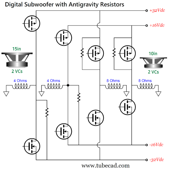
It is quite possible that the two dual-voicecoil woofers would prove less expensive than a single custom-made 15in woofer with four voicecoils. In addition, the two woofers would offer greater power handling. I quite like the look of this subwoofer. We can get clever and add four resistors to undo the cone shift due to gravity.
The 15in woofer fires downward, thus gravity pulls the cone positively (i.e. down), moving the voicecoil out of the center of its magnetic flux. The added resistors apply a negative current flow that returns the cone to its neutral position. The 10in woofer fires upward, thus gravity pulls the cone negatively (i.e. down), which the added resistors undo by pulling the cone up. Since gravity is a constant force, the resistors should be replaced with constant-current sources, but this arrangement should prove good enough with digital pulses. Here is the overview for this 3-driver DAH subwoofer:
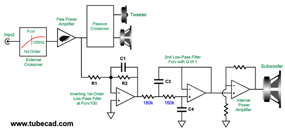
The 8in woofer can be further aided by employing some form of servo-feedback control to ensure accurate bass reproduction. By the way, there's no reason this digital-analog hybrid concept cannot be applied to a fullrange loudspeaker with built-in subwoofer. Post 553 reveals my genius-grant-worthy ™ idea of how to incorporate an internal powered subwoofer within a fullrange loudspeaker along with a 1st-order high-pass filter for the external power amplifier. This post also contains a section titled, "Correcting Woofer Non-Linearity," which certainly has application to subwoofers. (Imagine if both of the larger woofers held four voicecoils. This would deliver the top 8 bits, the most amplitude significant bits, to these two woofers, while the third and smallest driver would handle the remaining bottom 8 bits. The resulting efficiency gain would prove staggering, which would make use in theaters, stadiums, concert halls compelling.)
Music Recommendation: 24-Bit, 192kHz Jazz
//JRB
Did you enjoy my post? Do you want to see me make it to post 1,000? If so, think about supporting me at Patreon.
User Guides for GlassWare Software
For those of you who still have old computers running Windows XP (32-bit) or any other Windows 32-bit OS, I have setup the download availability of my old old standards: Tube CAD, SE Amp CAD, and Audio Gadgets. The downloads are at the GlassWare-Yahoo store and the price is only $9.95 for each program. So many have asked that I had to do it. WARNING: THESE THREE PROGRAMS WILL NOT RUN UNDER VISTA 64-Bit or WINDOWS 7, 8, and 10 if the OS is not 32-bit or if it is a 64-bit OS. I do plan on remaking all of these programs into 64-bit versions, but it will be a huge ordeal, as programming requires vast chunks of noise-free time, something very rare with children running about. Ideally, I would love to come out with versions that run on iPads and Android-OS tablets.
|
I know that some readers wish to avoid Patreon, so here is a PayPal button instead. Thanks.
John Broskie
John Gives
Special Thanks to the Special 90 To all my patrons, all 90 of them, thank you all again. I want to especially thank
I am truly stunned and appreciative of their support. In addition I want to thank the following patrons:
All of your support makes a big difference. I would love to arrive at the point where creating my posts was my top priority of the day, not something that I have to steal time from other obligations to do. The more support I get, the higher up these posts move up in deserving attention. If you have been reading my posts, you know that my lifetime goal is reaching post number one thousand. I have 393 more to go. My second goal was to gather 1,000 patrons. Well, that no longer seems possible to me, so I will shoot for a mighty 100 instead. Thus, I have just 8 patrons to go. Help me get there. Thanks.
New URL of the GlassWare website |
||||
| www.tubecad.com Copyright © 1999-2025 GlassWare All Rights Reserved |


