| John Broskie's Guide to Tube Circuit Analysis & Design |
| September 09 2025 | Post Number 625 |
||||||||||||||||||||||||||||||||||||||||||||||||||||||||||||||||||||||||||||||||||||||||||||||||||||||||||||||||||||||||||||||||||||||||||||||||||||||||||||||||
Mixed-Mode Output Stages We have few rules of operation about which we are certain; such as, all single-ended amplifiers must run in strict class-A; and, push-pull output stages must operate their output devices in current anti-phase to each other, whether in class-A, class-B, or class-AB. Do not imagine that transitioning exclusively to class-D power amplifiers, say due to an EU or UN decree, will sidestep the confusion, as class-D amplifier classification will, soon enough, splinter also into many sup-groups. For example, we already have the distinction between class-D power amplifiers with cheap and lightweight switch-mode power supplies and those with expensive and massive conventional power supplies; inductor-output and inductor-free output; and there's the split between single-output versus Bridge-Tied Load (BTL) output. Then there is the issue of those output stage topologies that elude easy classification. For example, a seemingly single-ended amplifier that on closer inspection reveals its push-pull operation. A "steered constant-current source" is not a constant-current source, as its current flow varies with the applied input signal; furthermore, since the steered-current source's conduction is in anti-phase to the output tube's, it's a push-pull output device, making the power amplifier, in fact, a push-pull design—in spite of it holding a single output tube. This example falls into the category of deceptive designs, so deceptive that its originator was also deceived. Next, we have output stages that go beyond hybrid by being mixed-mode. A simple example is the push-pull class-AB amplifier, as the amplifier idles in class-A and only slips into class-B when the output current demands exceed twice the idle current. Class-G amplifiers alter the power-supply voltages on the fly. As a boy, I owned a three-speed bicycle and two-speed minibike. I had to select the gear with the bicycle, but the minibike automatically shifted for me, based on engine RPM and stress. Today, I own a 15-speed bicycle, which might be a 21-speed. More isn't necessarily better. Class-G amplifiers are like multispeed bicycles, automatically switching up and down in power-supply rail voltages as needed. Push-pull class-A, class-B, class-AB amplifiers all run in class-A if the output signal is small enough and the load impedance high enough. Ask the burliest push-pull class-A power amplifier to deliver 40Vpk into a 1-ohm load and it becomes a class-AB power amplifier.
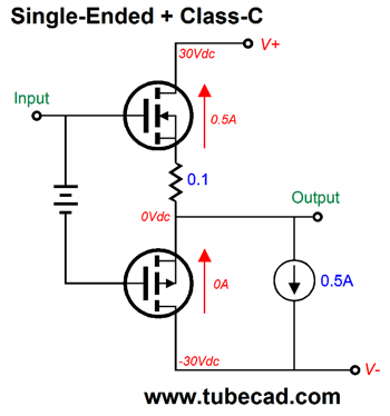
Okay, what if we had another option, one wherein the output stage would smoothly and automatically transition from single-ended to push-pull? Long-time readers will remember me floating this idea and creating topologies to fulfill it. For example in Post 333, we see the following output stage that runs in single-ended up to a certain power output and then transitions to push-pull operation.
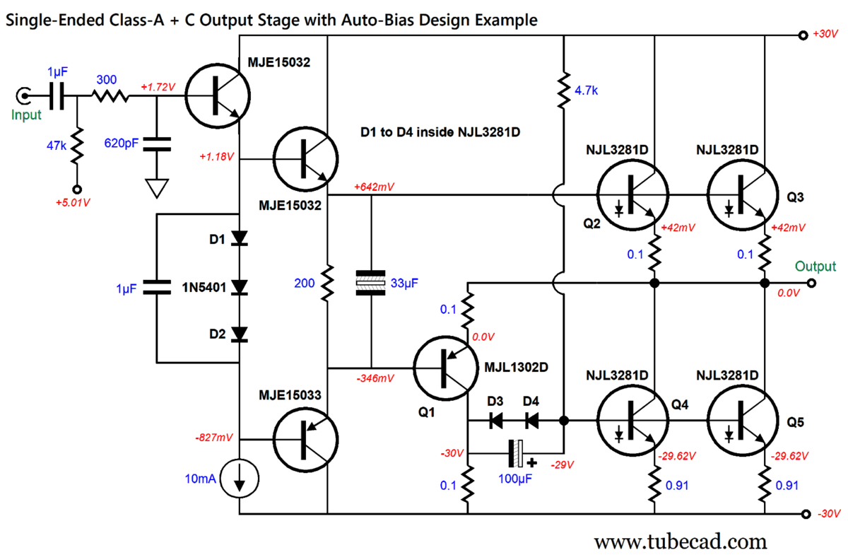
At idle, the P-channel MOSFET draws no current. Once the negative output voltage swing demands more current than the constant-current source can deliver, the bottom MOSFET will conduct, pulling the output further negative. Post 364 showed transistor-based versions of this idea. And Post 582 revealed an enhanced auto-bias version of a circuit from Post 333 that made use of the diodes located with the four NJL3281D ThermalTrak™ output transistors.
Transistor Q1 draws no current at idle, while the bottom two NJL3281D transistors function as constant-current sources, with each drawing 418mA. Once again, as the negative output voltage swing demands more current than the constant-current sources can deliver, transistor Q1 switches on, causing the constant-current source transistors to begin conducting more, transforming the output stage into push-pull one. Transistor Q1 is the only device to run in class-C. This design yields 2.8W of single-ended output and a little over 40W of push-pull output. By the way, we are not limited to solid-state amplifier designs, as tubes can be invited to the party. In fact, back in 2002, in an article I wrote titled, Mixed-Class & Mixed-Topologies Amplifiers, I showed how a conventional tube-based, push-pull, transformer-coupled amplifier could be modified to shift from single-ended to push-pull operation.
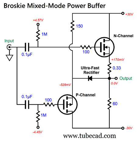
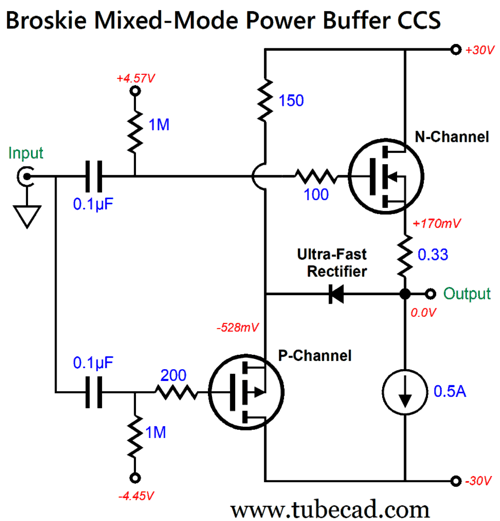
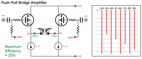
The problem with the above design is that no tube should ever experience heated cathodes without drawing current, as it leads to cathode poisoning (i.e. cathode-interface build up). It's much better to let the top EL34 function as a constant-current source that switches to push-pull operation after some threshold current demand is reached. Well, last year I was trying to devise the simplest mixed-mode, dual-mode, SE/PP class-A/AB power buffer possible. My goal was to get 1 watt of single-ended output before transitioning to push-pull mode. With an 8-ohm loudspeaker, 1W equals 4Vpk and 0.5A of peak current flow. Thus, the single-ended portion of the design must idle at 500mA. In contrast, the push-pull portion of the circuit could idle any current or no current flow whatsoever. Here it what I came up with, that is after I thought of using a commutator diode to separate the single-ended portion from the push-pull half.
The N-channel MOSFET idles at 0.5A of current flow, as 30V divided by 60 ohms equals 0.5A. The resistor loading is far from ideal; if nothing else, it is quite inefficient. The maximum peak negative current swing the 60-ohm allows for is 441 mA (-3.5V with an 8-ohm load). And, at the other extreme of peak output voltage swing, say 26Vpk, the resistor will draw 933mA of peak current. The obvious workaround is to replace the resistor with a constant-current source.
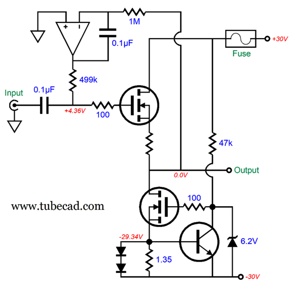
Although the constant-current source could be made up from two LM317-HV voltage regulators configured as constant-current sources, working in parallel, a better approach is to use discrete parts. Why? If nothing else, higher voltage and power limits. In addition, it can prove safer, if the fusing is done correctly.
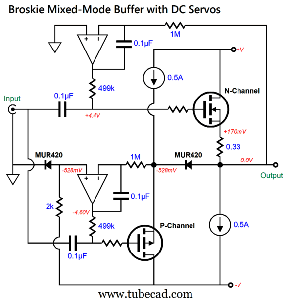
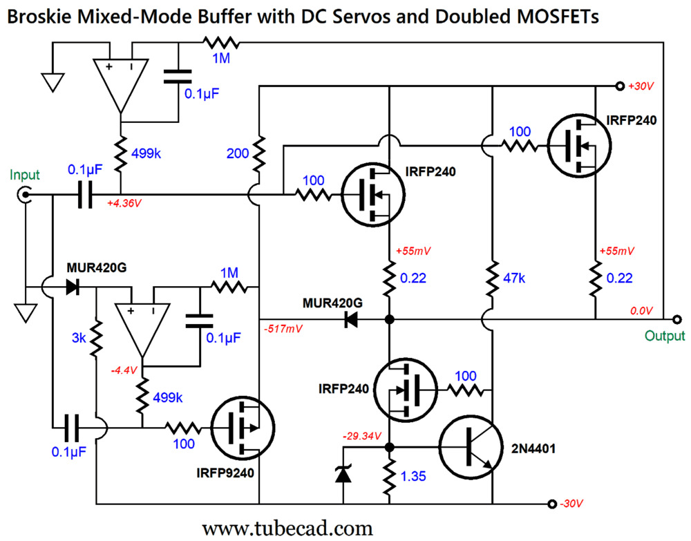
If the fuse blows, the output will not slam down to the negative power-supply rail in this arrangement, as bottom N-channel MOSFET's gate voltage will collapse to -30V, thereby shutting down the MOSFET's current conduction. (If the bottom fuse blows, the DC servo will keep the output at 0Vdc.) The DC servo can run off much lower bipolar power supply rail voltages, say ±12Vdc, which can be derived from the higher rail voltages. By the way, the selection of capacitors and resistors within the DC servo were carefully chosen to prevent peaks in the low frequencies. Here are both DC servos:
The bottom DC servo does not use ground as a reference voltage; rather, it uses the negative voltage drop across the left MUR420 rectifier, which sees a 14.75mA current flow through the 2k resistor. This is also the amount of leakage current that will flow at idle through the MUR420 on the right. The two rectifiers should share the same temperature, which could be achieved by simply placing the two side-by-sides and shrink-wrapped together. While delivering power to the loudspeaker, the commutator diode will heat up, thereby decreasing its threshold turn-on voltage; but as the two are tightly pressed together, the reference diode will also become equally hot. That is the situation at idle. When the input signal swings positively, the rectifier on the right, the commutator diode, ceases to conduct, as the P-channel MOSFET's source quickly swings too positive for the forward-on voltage of the diode. When the signal swings negatively, the N-channel MOSFET is dragged down by the external load, so the P-channel MOSFET overtakes it and current flow through the commutator diode increases. If the output voltage swing is great enough, the N-channel MOSFET will stop conducting altogether, and all the current into the loudspeaker will flow through the diode and the P-channel MOSFET.
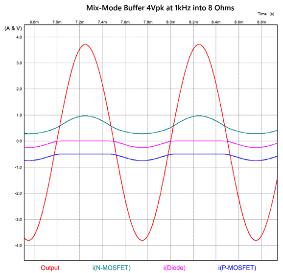
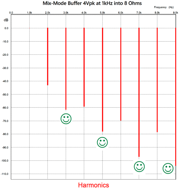
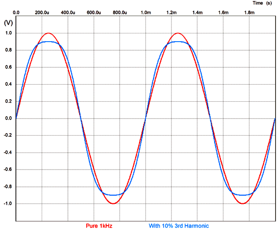
Note that the output signal does not match the input signal of 4Vpk in amplitude, and the negative swing exceeds the power supply swing. Also note that the P-channel MOSFET's current conduction never falls below 0.5A, while the commutator diode and N-channel MOSFET can cease conducting current. In other words, what we get is an imbalanced push-pull operation, along with auto-biasing. All by itself, auto-biasing is a worthwhile goal. But what does an imbalanced push-pull operation deliver? An astoundingly rare and desirable output harmonic structure. Sonic gold, the aural antidote to the typical push-pull sonic signature.
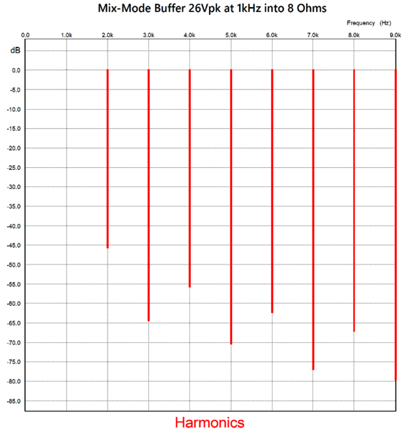
Note that the odd-order harmonics, the 3rd, 5th, 7th, and 9th, are further reduced relative to the even harmonics: the inverse of push-pull output stages. The important question is does this astoundingly rare and desirable output harmonic structure extend up to full output? Oh yes, it does:
An output voltage swing of 26Vpk into an 8-ohm load equals 42.25W of power. We can double up on the N-channel MOSFET output devices, which would halve their dissipation at idle and lower the output impedance. (Which assumes matched MOSFETs, but these are easy to obtain, as modern production technique are such that all the MOSFETs in the shipping tube come pretty much matched.)
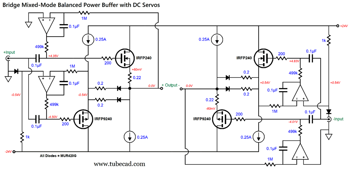
If we desire an even lower output impedance (but at the cost of a more push-pull harmonic structure) we can replace the source resistors with rectifiers.
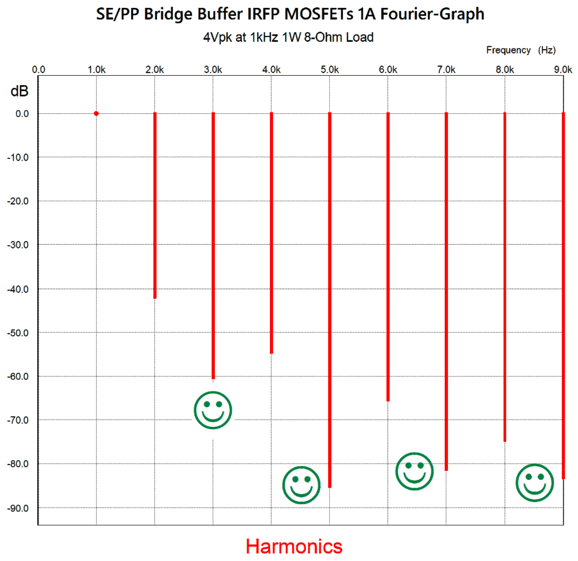
Note the relatively low idle current flow of 1A total. Also note that the topology on the right is the flip version of that on the left. Had I simply duplicated the topology on the left, we would lose the single-ended flavor and plunge into pure push-pull harmonics. Speaking of harmonics, here are some.
The THD is about 1%, which is a lot for solid-state, but low for tube-based amplifiers. Note the lovely single-ended cascade of harmonics and the astoundingly low 3rd harmonic. The third harmonic sounds compressed, lifeless, as flattened, compressed, peaks result.
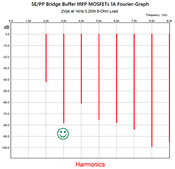
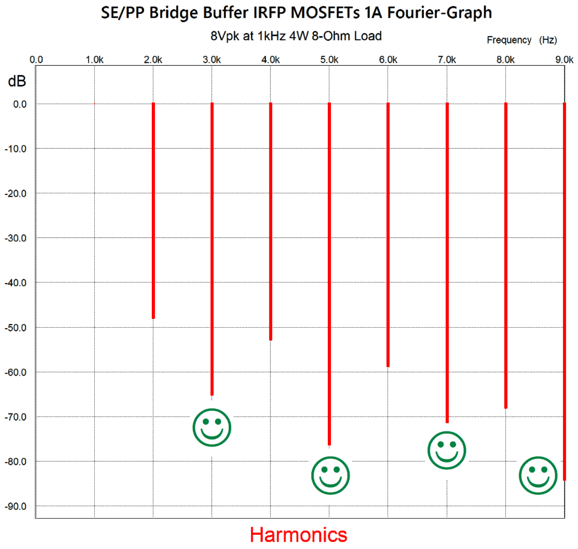
Next, 1W of output into 8 ohms.
Happy faces all the way around, as all the odd harmonics are wonderfully suppressed. This is the exact opposite of what most would expect to see coming from a balanced bridge amplifier.
We increase the voltage swing to 8Vpk, resulting in 4W of power output.
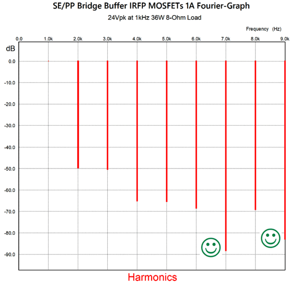
Note that the THD has fallen, due to the decrease of 2nd harmonic. With 36W of output, some of the odd-order harmonic suppression falls away.
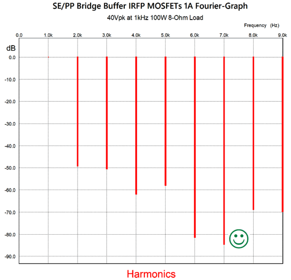
Only the 7th and 9th harmonics shine now. Mind you, the sound would still sound relatively good, if compared with the typical solid-state power amplifier, even a high-end solid-state amplifier. The final increase is to 40Vpk, which translates into 100W into an 8-ohm load.
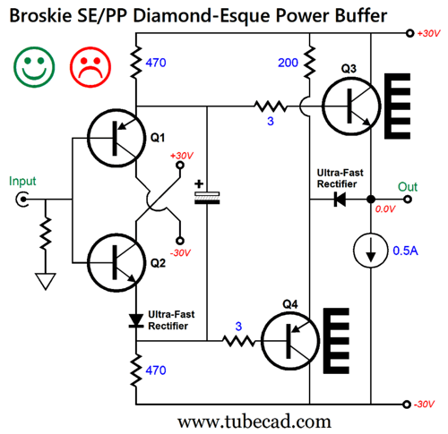
It's possible that with multiple output devices in parallel we might retain more of the astounding odd-harmonic reduction. What about using different solid-state output devices, such as power transistors? Well, I tried the following:
This simple power buffer passed the SPICE simulation tests —at first. In other words, with ten-cycles of 1kHz input signal, the output was clean. The problem is that transistors, unlike MOSFETs, draw current from their bases, lots of current, which means that the electrolytic capacitor will discharge up with long sustained, high-input signal. The lower voltage drop across the capacitor will introduce a DC offset and increase distortion. We could increase the capacitor's value, say to 10kµF, which will slow down the rate of discharge; but once discharged, the time it takes to charge the capacitor will correspondingly increase. Of course, a lot depends on the type of music played and the amount of power delivered to the loudspeaker. One workaround would be to replace the 470-ohm collector resistors with constant-current sources, but some discharging will still occur. Speaking of constant-current source, this is what the constant-current sources would look like:
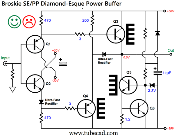
Sometimes we can be too parsimonious, too tightfisted in allocating electronic parts. Less isn't always more; sometimes it's less. This is one such example. By adding an extra buffer stage in the middle, we greatly unload the input stage and allow the use of larger-valued collector resistors.
Transistors Q3 and Q4 drive the output transistors (Q5 and Q6) to full output. But impose about a hundred times lighter load impedance to the input stage. The added diodes are there to provide needed voltage shifts (i.e. voltage drops) to establish no DC offset at the output. Only one of the two diodes in series below Q2 needs to be physically coupled with the output diode. Transistors Q1 and Q2 should attach to the heatsink near the output transistors Q5 and Q6, which will minimize the output DC offset. Here is the fleshed out version:
How well does this power buffer work in SPICE simulations? Crazy good.
With one watt of power output into an 8-ohm load, the THD is about 0.1%. More importantly, the harmonic structure is entirely single-ended in its linear cascade of harmonics. The single-ended cascade still persists at 4W of output.
At full output, 36W, some push-pull flavor appears:
Note that the 7th and 9th harmonics fail to conform to the downward slope. The THD is around 0.8%. Considering that this is negative-feedback-free design, this is excellent. Speaking of negative feedback, we could try using an output stage configuration that contains its own negative feedback, e.g. the compound stage.
Transistors Q5 and Q6 are the master transistors that enslave transistors Q7 and Q8, as they control their current conduction. This setup will further unload the input stage and linearize the output transistors. To obtain good thermal tracking and an intrinsically low DC offset, transistors Q1 and Q5 should share the same heatsink; likewise Q2 and Q6 transistors. Of course, an input coupling capacitor and DC servo could be used. Good as this setup sounds making a compound output stage work isn't easy, especially when a global negative-feedback-loop is employed. Fortunately, this power buffer does not hold a global negative-feedback-loop; still, we should truncate the output stage's high-frequency response to prevent high-frequency oscillations.
Note the higher-valued emitter resistors in the input stage. The 10-ohm resistors and 470pF capacitors impose a high-frequency bandwidth limit of around 210kHz. Also note that there's no series 0.33-ohm resistor with the output commutator diode. How well did this compound version work in SPICE simulations? Very well indeed, as we see low THD and a nice single-ended cascade of harmonics.
THD is below 0.1%. (By the way, with a 1kHz input signal, the THD would be lower still.)
With 8Vpk of output voltage swing (4W) is pretty much where I would expect to see the most distortion. Still, the single-ended cascade of harmonics lingers. At full output, 24Vpk (36W), the wonderfully extraordinary cascade of harmonics shows up.
Note the extra reduction of the 3rd, 5th, and 7th harmonics. I must point out that although this is the last variation, it is not necessarily the one I deem the best.
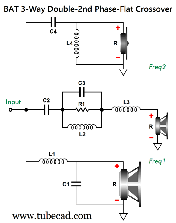
Three-Way 2nd-Order BAT
Since the three speaker drivers sum to phase flat, this is a transient-perfect crossover. In other words, a single pulse or square waves go in and a single pulse or square waves come out. This is not the case with 2nd-order, 3rd-order, or 4th-order crossovers. They can deliver a flat frequency response, but their mangling of the phase prevents a single pulse or square waves emerging anything other than mangled. The tweeter and woofer both get a 2nd-order crossover filter with a Q of 0.5, the same as the Yamanaka and Linkwitz-Riley alignment, while the midrange driver sees lumpy 1st-order low and high cutoffs. The midrange driver must offer a slightly higher SPL than the woofer and tweeter; the amount of extra SPL depends on the ratio between the higher and lower crossover frequencies, with a high of 6dB with a ratio of 1 and a low of 2.3B with a ratio of 10. The following tables cover crossover-frequency ratios from 1 to 10. For example, crossover frequencies of 300Hz and 1200Hz conform to a ratio of 4, as does 750Hz and 3kHz. With this ratio, we look down the "4" column and see that the midrange driver must deliver 3dB more SPL than the woofer and tweeter. We also see that resistor R1 must be 1.1 ohms. (I choose resistor values that could be easily be bought or put together; for example, 1.1 ohms is a standard resistor value, but 1.24 ohms isn't, but can be made up of a 1-ohm resistor in series with a 0.24-ohm resistor, which are also standard values.) The midrange driver should be a wide-bandwidth type, such as a fullrange driver, as it must cover a wide bandwidth with -6dB per octave cutoff slopes.
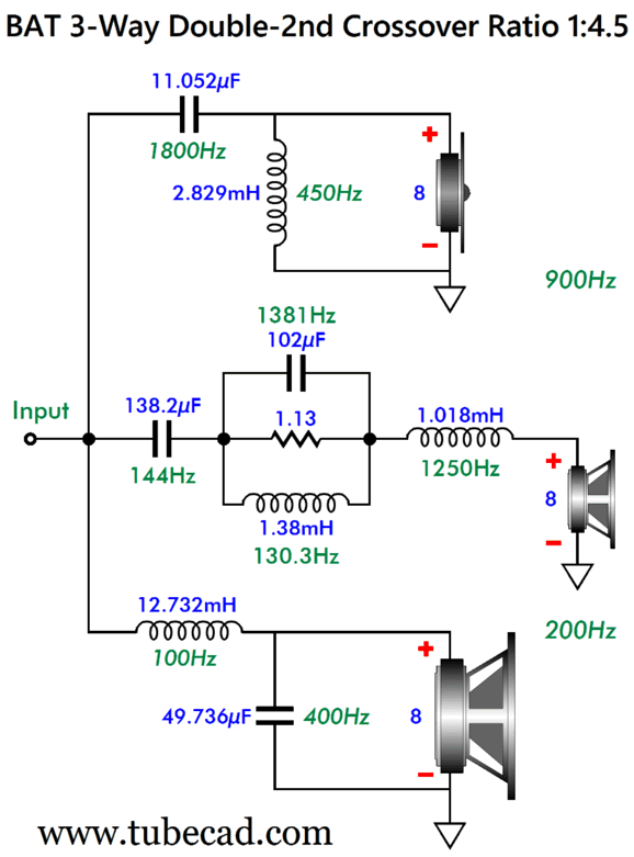
What if your desired crossover frequencies are 200Hz and 900Hz, making a ratio of 4.5? You could try extrapolating the C2, C3, L2, L3, and R1 values based on the 4 and 5 ratio columns. For example, R1 would then equal (1.1 + 1.24)/2 or 1.17 ohms; capacitor C2 would be found by (27500 + 27180)/2/F1 or 27340/F1. I would still run SPICE simulations on these derived values. Okay, I just did follow that interpolation procedure and the results were not good. Thus, I set about fiddling with the crossover part values and found that this set of values worked well with the midrange driver delivering an SPL 2.95dB higher than the woofer and tweeter:
I believe that interpolation trick would work, however, if resistor R1's value were held constant. Note, however, that resistor R1 now equals 1.13 ohms. Eventually, some math wizard will discern the latent formulas for the crossover part values for the midrange driver. The starting (or ending) point is when crossover frequencies Fcrv1 = Fcrv2, as this is basically a variation on the Yamanaka phase-flat crossover.
Music Recommendation: Kronos Quartet, In Formation I used to be a huge Kronos Quartet fan, which explains why I own so many of their CDs. Somehow I missed their first studio album, In Formation, a failing that my Friend Steve corrected recently. Thanks Steve. When the CD's cover lists the recording engineer, Professor Johnson in this example, you know that sonic presentation was as important as the music performance. At the Kronos Quartet website, we see the following quote:
Joel Flegler, Fanfare Magazine We also read:
//JRB PS Summary
Did you enjoy my post? Do you want to see me make it to post 1,000? If so, think about supporting me at Patreon.
User Guides for GlassWare Software
For those of you who still have old computers running Windows XP (32-bit) or any other Windows 32-bit OS, I have setup the download availability of my old old standards: Tube CAD, SE Amp CAD, and Audio Gadgets. The downloads are at the GlassWare-Yahoo store and the price is only $9.95 for each program. So many have asked that I had to do it. WARNING: THESE THREE PROGRAMS WILL NOT RUN UNDER VISTA 64-Bit or WINDOWS 7, 8, and 10 if the OS is not 32-bit or if it is a 64-bit OS. I do plan on remaking all of these programs into 64-bit versions, but it will be a huge ordeal, as programming requires vast chunks of noise-free time, something very rare with children running about. Ideally, I would love to come out with versions that run on iPads and Android-OS tablets.
|
I know that some readers wish to avoid Patreon, so here is a PayPal button instead. Thanks. John Broskie
John Gives
Special Thanks to the Special 91! To all my patrons, all 91 of them, thank you all again. I want to especially thank
I am truly stunned and appreciative of their support. In addition I want to thank the following patrons:
All of your support makes a big difference. I would love to arrive at the point where creating my posts was my top priority of the day, not something that I have to steal time from other obligations to do. The more support I get, the higher up these posts move up in deserving attention.
If you have been reading my posts, you know that my lifetime goal is reaching post number one thousand. I have 375 more to go. My second goal was to gather 1,000 patrons. Well, that no longer seems possible to me, so I will shoot for a mighty 100 instead. Thus, I have just 9 patrons to go. Help me get there. Thanks.
New URL of the GlassWare website |
||||||||||||||||||||||||||||||||||||||||||||||||||||||||||||||||||||||||||||||||||||||||||||||||||||||||||||||||||||||||||||||||||||||||||||||||||||||||||||||||


| www.tubecad.com Copyright © 1999-2025 GlassWare All Rights Reserved |