| John Broskie's Guide to Tube Circuit Analysis & Design |
| September 30 2025 | Post Number 626 |
||||
Single-Ended Bootcamp
The background idea was that smart phones, laptops, and MP3 players all assume 16-ohm to 32-ohm headphones, which means they only put out a peak-voltage swing of about 1V. Sadly, 300-ohm headphones need more voltage to dance; hence the need for a headphone amplifier that offered more voltage gain, but at less peak current flow. In other words, this is a nice fit for tube-based designs, as tubes are current limited, not voltage limited. So, how much peak voltage swing do we need? Decades ago, I attach the scope probes to the output of my headphone amplifier and listened to my Sennheiser HD580 headphones at the highest SPLs that I could tolerate. I saw that peaks of 3V showed up on oscilloscope screen. Well, we only need divide 3V by 300 ohms to find the peak output current swing, which is only 10mA, which is well within the limits of a 6DJ8 or ECC99 or 5687. Of course, many other audio-signal triodes, such as the 6SN7 and 12AU7, can deliver this much cathode current, but due to their higher plate resistances (rp), they require higher B+ voltages. For example, a 6DJ8 with a cathode-to-plate voltage of 62V and cathode-to-grid voltage of 0V draws 20mA, but a 6GC7 or 6SN7 needs a voltage of 160V do the same. In other words, we seek low rp and high transconductance (gm).
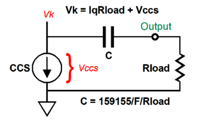
Here is the formula for the required B+ voltage, when the cathode is at ground potential (0V): Vb = 2Iq(rp + Rload) If you are wondering why I specified a current draw of 20mA, when the peak current swing is only 10mA, the answer is that a cathode follower loaded by a 10mA constant-current source must idle at 10mA and swing 20mA at peak output, as it must not only pull up against the 300-ohm load, but also the constant-current source (CCS), making a total of 20mA, 10mA for the load and 10mA for the CCS. When the output swings down to -3Vpk, the cathode follower has ceased to conduct altogether and 10mA constant-current source does all the tugging down against the 300-ohm load.
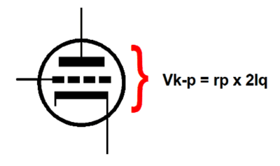
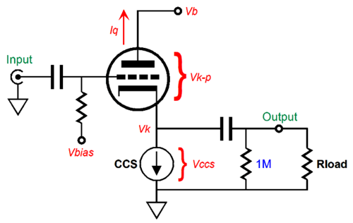
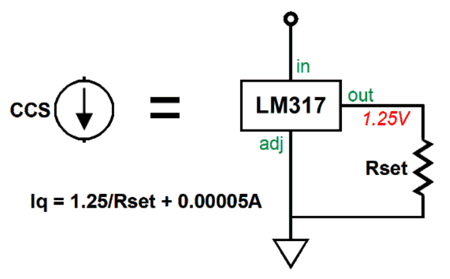
This is the cathode follower output stage. The constant-current source is set to the desired idle current; in this example, 10mA. The next step is to determine the required cathode voltage. Normally, we use the following formula to find the needed cathode voltage to establish a desired idle current with a predetermined B+ voltage. Vk = (Vk-p - Iq ·rp) / (mu + 1) Where mu is the triode's amplification factor. But this won't necessarily give us enough voltage headroom to both drive the load impedance and not run into the constant-current source's minimum voltage drop, which cannot be zero volts. Speaking of the constant-current source, we can use the famous LM317 voltage regulator.
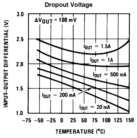
Since so little current is required and so little voltage dropped across the IC, we can forgo giving it a heatsink. The LM317's data sheet shows the following graph of the voltage drop versus device temperature with various current flows.
Note that this shows the voltage drop across LM317's input to output pins, not from ground to the input pin. In other words, we must add 1.25V to the shown drop-out voltage. For example, with 25C and 20mA, we get a drop-out voltage of about 1.5V, to which we add 1.25V, bringing us to 2.75V. This voltage must be added to the peak output voltage swing (3Vpk), which gives us the require cathode voltage, 5.75V. To be extra safe, add another volt, 6.75V.
The output coupling capacitor formula is easy enough. With a load impedance of 300 ohms, any coupling capacitor value 30µF and up is usable. In fact, since the cathode voltage is so low, we could use a non-polarized electrolytic capacitor bypassed with a small-valued film or PIO capacitor. The next voltage to be calculated is the grid-bias voltage.
Remember that grid-bias voltage is relative to the cathode, not ground. We return to the formula for finding the cathode voltage: Vk = (Vk-p - Iq ·rp) / (mu + 1) If we do the math, we get a result of -0.9V, which we then add to the previous voltage of 6.75, leaving us with 5.85V relative to ground potential. The B+ voltage must be at least equal to 5.85v + 62V, if we are using a 6DJ8 triode. Are those results set in stone, inviable and sacrosanct? No, not even close. What we have is a good first approximation of what is needed. It does, however, save us a lot time just striking out at random voltages and part values. This is why the backs of envelopes and pencils exist. When I got home, I ran SPICE simulations on this design, using my calculated voltage as guides.
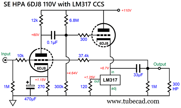
The above proved the most promising, within reason. What sort of reason? For example, we do not want the cathode follower's 6DJ8 triode to dissipate too much heat, and we want to make sure that the constant-current source draws a bit more than 10mA to ensure a clean negative output voltage swing. At the same time we want to give the input triode a fairly high plate resistor value and cathode-to-plate voltage. Thus, the 100Vdc B+ voltage. This is an OTL amplifier that uses negative feedback, which sets a fixed gain of 1:3 or +9.5dB. How much negative feedback? The open-loop gain is 1:18.8 or +25.5dB; subtract the closed-loop gain and we get 16dB of negative feedback. In SPICE simulations, the performance was admirable—well, at least in terms of THD, output impedance, and bandwidth. In terms of PSRR, which is critical in a headphone amplifier, not so much, as it was only -28dB at 100Hz. I figured it was time for me to apply some of my signature Aikido Mojo.
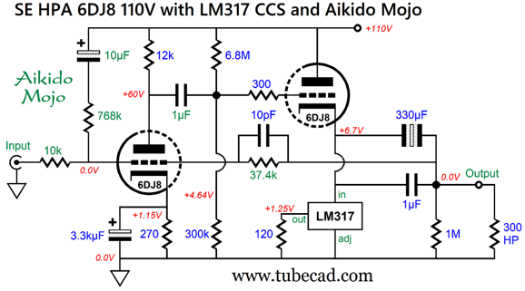
With the added Aikido-Mojo 768k resistor and 10µF capacitor, the PSRR improved by -40dB, bringing it down to -68dB. That's a one-hundredfold decrease. Bear in mind that this is the raw PSRR, absent any further noise-reduction ploys, such as chokes, RC filters, power-supply regulation …
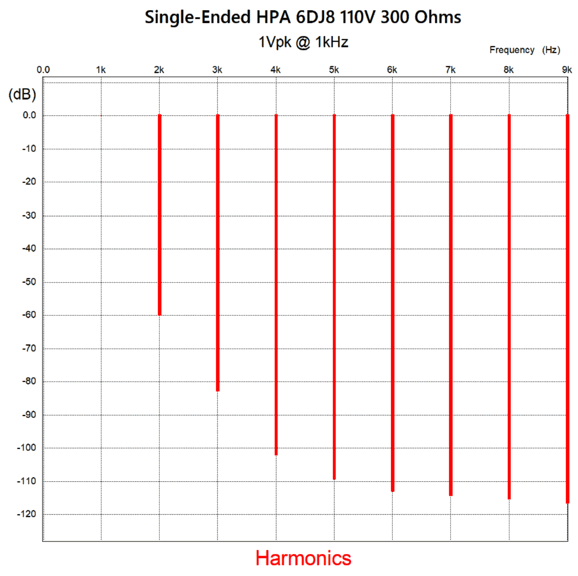
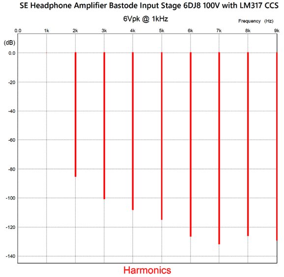
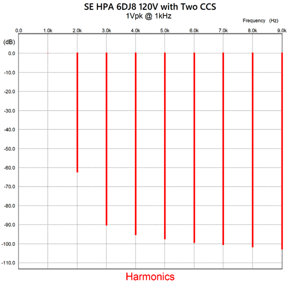
With 1Vpk of output at 1kHz, the THD is about 0.1% in SPICE simulation.
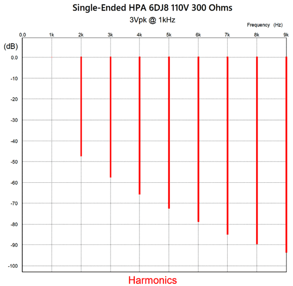
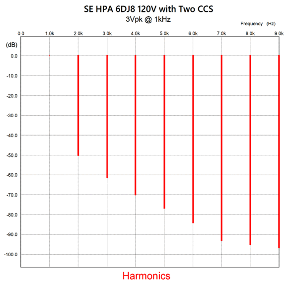
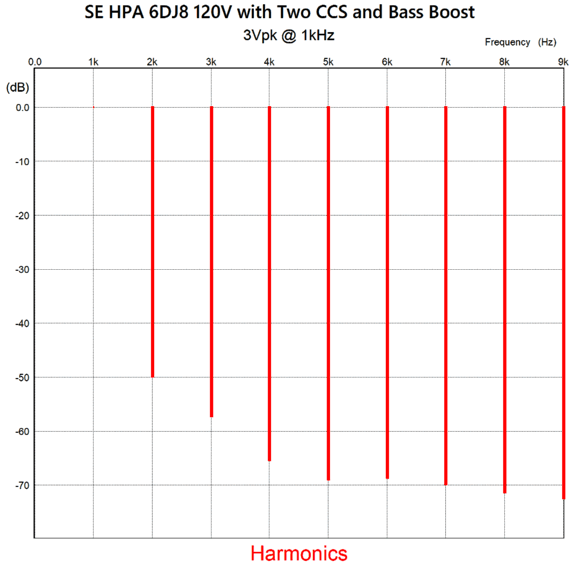
At full output, i.e. 3Vpk, the THD rises to 0.46%, but still retains the lovely single-ended cascade of harmonics.
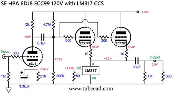
The problem with using a 6DJ8 as the output triode is that the high idle current flow of 10mA takes a bite out of the 6DJ8's longevity. In other words, if we use a triode with greater plate dissipation, such as the ECC99, we can expect a much longer tube life. Another issue might that although 3Vpk of output voltage swing delivers nine times more power into the 300-ohm headphone than the 1Vpk that smartphones put out, it may not still be enough. It we increase the potential output voltage swing to 6Vpk, the output stage now delivers 36 times more power. We could double on 6DJ8 triodes in the cathode follower stage or use two ECC99 triodes.
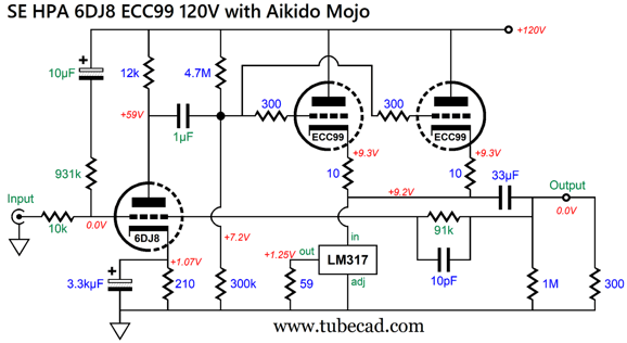
The LM317-based constant-current source now draws 21mA of current, so each ECC99 triode draws 10.5mA. The cathode follower cathode voltage has been upped to 9.2V due to the increase output voltage swing of 6Vpk. What are missing from the schematic are the negative-feedback loop and some Aikido Mojo.
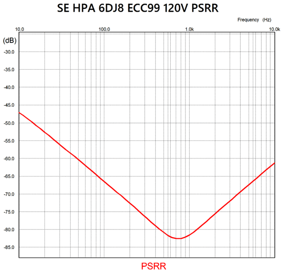
The 10k and 91k resistors set a gain of 1:6 or +15.6dB. The 931k resistor and 10µF capacitor inject a sampling of the power-supply noise into the 6DJ8's grid, resulting in the Aikido-Mojo boost in PSRR. Here is the PSRR graph.
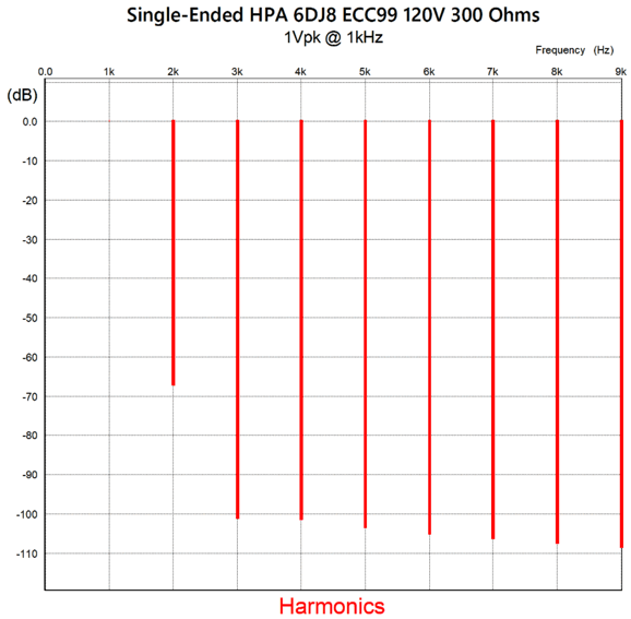
A PSRR of -66dB at 100Hz is excellent for any tube circuit. The distortion was super low with 1Vpk of output.
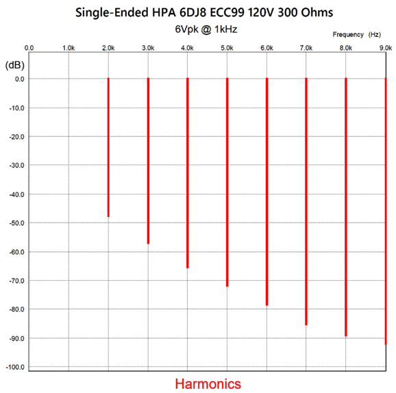
Note the relatively strong 2nd harmonic. At full output, the distortion rises, but still maintains the sweet single-ended cascade of harmonics.
By the way, the output impedance in SPICE simulations was 15 ohms. We finally arrive at the actual circuit that I sketched out in that waiting room.
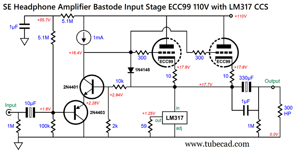
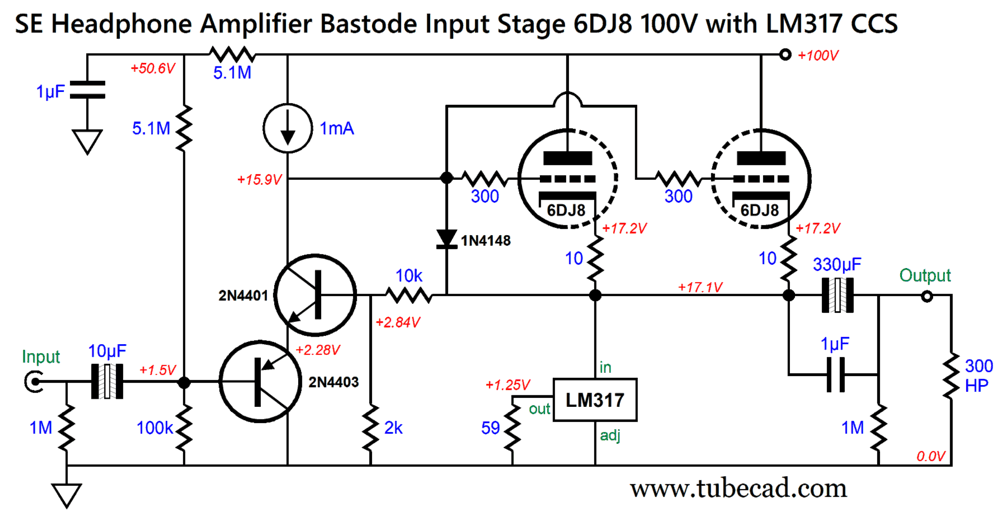
This is a hybrid headphone amplifier, as the tube-based input stage has been replaced by a transistor-based bastode differential amplifier. The negative-feedback loop no longer encompasses the output coupling capacitor, so I decided to radically increase the coupling capacitor value. In addition, this topology does not invert. Since we no longer have a tube-based grounded-cathode amplifier input stage, I wondered if we could use a 6DJ8 and a lower B+ voltage.
Note the 100Vdc B+ voltage, which results in a plate dissipation of only 0.87W for each 6DJ8 triode. Moreover, two 6DJ8 tubes have roughly the same combined heater-element dissipation of one ECC99, 4.6W versus 5W. The 10µF input coupling capacitor might be overkill, but when driving transistor bases a low-input impedance is desirable. Of course, the solid-state signal source (the smartphone or personal music player or DAC) will offer a low input impedance, but a 0.1µF input coupling capacitor would present an impedance of 79.6k at 20Hz; in contrast, the 10µF input coupling capacitor, only 79.6 ohms. (The reason polarized-electrolytic coupling capacitors used in CD players and DAC and other solid-state audio are often 33µF to 470µF in value is not to extend the low-frequency bandwidth but to reduce the capacitor's distortion. The greater the electrolytic coupling capacitor's capacitance, the lower the distortion. Non-polarized-electrolytic coupling capacitors are inherently low-distortion.) Interestingly enough, the 6DJ8 beat the ECC99 in SPICE simulations, delivering lower distortion.
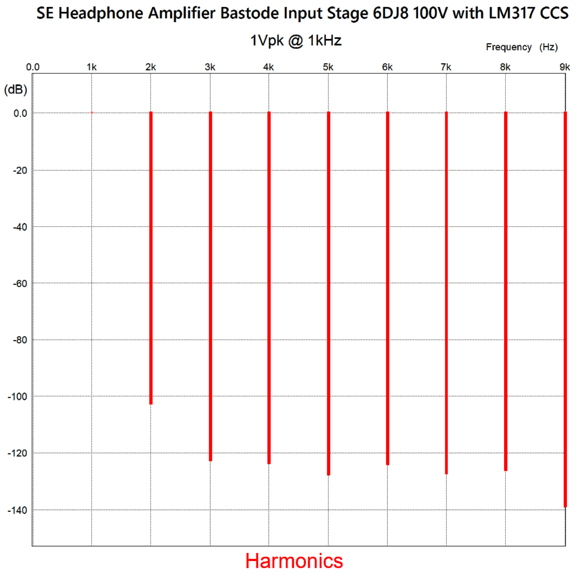
At full output, 6Vpk, we get the following:
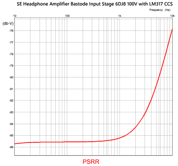
Nice. Let's assume that reality will prove ten times worse; nonetheless, the THD would only rise to 0.1% from 0.01%. The output impedance is less than one ohm, the result of the super high gain from the transistor-based bastode input stage. Here is the PSRR graph:
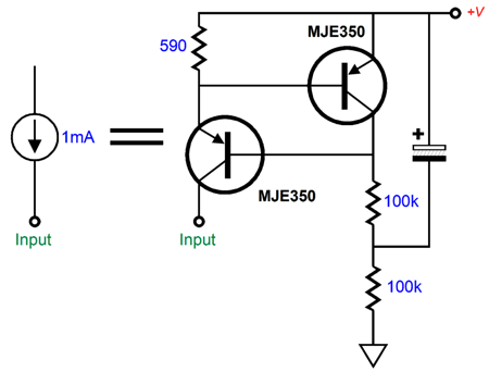
No doubt some are wondering about the 1mA constant-current source, asking where I can buy one of those. Rather than buy, it's better to build.
This constant-current source works extremely well. The way it works is simple enough: the MJE350 PNP transistor exhibits a base-to-emitter voltage of 0.59V, which we use as free voltage reference. The top transistor controls the bottom transistor's current conduction—but in anti-phase. When the top draws more, the bottom draws less, and vice versa, i.e. conversely. If the voltage drop across the 590-ohm resistor exceeds 0.59V, the top MJE350 responds by increasing its conduction, thereby forcing the bottom MJE350's base to see higher voltage, which in turn causes the bottom MJE350's emitter to follow, reducing the voltage drop across the 590-ohm resistor. In other words, this circuit strives to constantly maintain a fixed 0.59V voltage drop across the 590-ohm resistor; and a constant voltage drop equals a constant-current draw. If we desire a 10mA current draw, we reduce the 590-ohm resistor value to one tenth or 59 ohms.
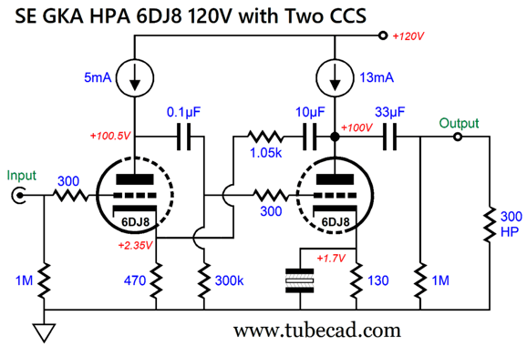
Now for Something Different
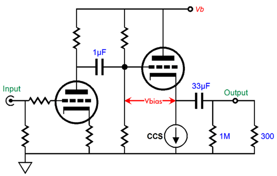
We see two grounded-cathode amplifiers in cascade. The input signal enters the left triode's grid, where it gets both amplified and inverted at that triode's plate. This signal is then passed on via the 0.1 µF coupling capacitor to the right triode's grid, whereupon it is once again amplified and inverted, with the two inversion series yielding no phase inversion at the output. The 470-ohm cathode resistor and the 1.05k resistor and 10µF capacitor define a negative-feedback loop. To see this works just imagine forcing a positive voltage pulse on the output.
The positive pulse is both relayed and attenuated by the negative-feedback loop to the input triode's cathode. Signals enter a triode's cathode are amplified but not inverted at its plate, as the triode now functions as a grounded-grid amplifier. The non-inverted and greatly amplified pulse is then fed into the right triode's grid, forcing much greater current conduction from this triode, thereby pulling down its plate voltage in response, bucking the positive pulse with a negative one. Negative feedback in a nutshell. If we substitute the pulse with distortion generated by the amplifier circuit itself, the distortion fails to match the input signal, so the same mechanism works to erase the distortion. Speaking of distortion, here is the SPICE-generated Fourier graph:
The THD is about 0.1%. The relatively strong 2nd harmonic bestows a slight warmth. At full output, which is only 3Vpk, due to the 13mA constant-current source, the harmonics take on that single-ended cascade so prized by our ears.
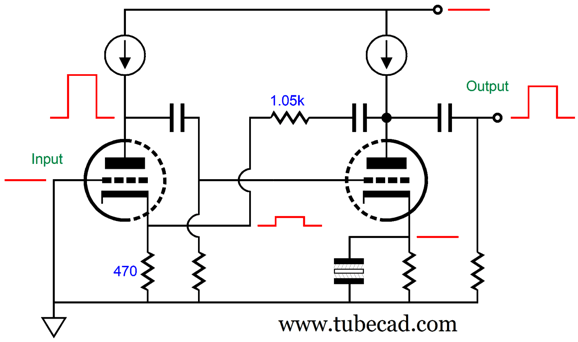
Note that the negative feedback, however, does not extend down to DC, as the two internal coupling capacitors break the DC connection between the triodes. This means that at extremely low frequencies there is negligible negative feedback and, thus, high gain, roughly equal to mu ², where mu is the triode amplification factor; in the case of the 6DJ8, about 1:1,000 or +60dB. Is this a problem? Not really, as the 0.1µF coupling capacitor limits the amount of low-frequency signal that appears at the second triode's grid. Okay, what if we take this potential problem and turn it into an asset? How so? We juggle the two internal capacitor values to create a bass boost.
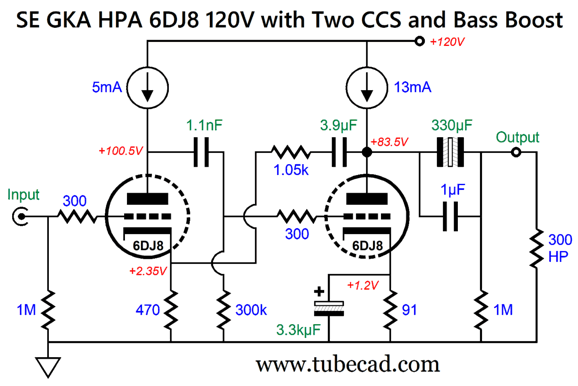
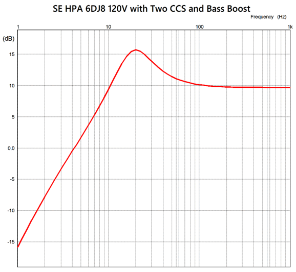
Note that the 0.1µf capacitor was replaced by a 1.1nF (0.0011µF) capacitor and the 10µF by a 3.9µF capacitor. These values create a +6dB bass hump at 20Hz.
With rare exception, most headphones droop at the low frequencies, giving them their signature thin sound. Will this feedback-based low-frequency boost create extra distortion? It certainly will at 20Hz, if for no other reasons that we have greater gain and less negative feedback; but once the frequency plot flattens, not really.
Interestingly, the SPICE Fourier analysis is sensitive to phase shift, whereas a THD meter isn't. In other words, we need not worry. Returning to the circuit, note the other changes, such as the 330µF non-polarized electrolytic capacitor and the lower plate voltage on the output triode. Since we put in place a bass boost, we should ensure a low output impedance for the headphones, which the bigger capacitor helps ensure. At the same time, however, we run into the problem that non-polarized electrolytic capacitors top out at 100Vdc; thus, the lower plate voltage. Another issue might be our desire for greater output voltage swing. The easy workaround is to use two 6DJ8 triodes in parallel in the second stage. A three tube headphone amplifier would look cool, but might make the heater power supply a tad more difficult.
Music Recommendation: Demo-Grade Bass Tracks The first track I just discovered at a friend's house, "Chocolate Chip Trip" by prog-rock band Tool on their album Fear Inoculum.
Do not expect to be hammered in the beginning, as that track, like many other bass showcase tracks, saves the heavy ammo for the end. Asides from great bass, the track delivers an astoundingly huge stereo image.
Just about any album by Mickey Hart qualifies as a bass-extravaganza. On his album Ramu, I quite like the track "Nacare." Good bas doesn't mean just organ pipes and big drums, as it also refers to the ability to impart a sense of the music hall's size. In fact, the near silent portions of some albums, such as the recording of Benjamin Britten's Noye's Fludde allows us to sense extent of venue; absent deep bass, we cannot hear dimensions.
Returning to Mickey Hart, his album, In the Groove, departs from his other albums by not so much delivering massive bass, but high-quality bass, bass good enough to hear the room acoustics. For example, the tracks "Storm Drum" and "Drops" do a great job of portraying a near ominous if not menacing huge chamber.
Of course, I cannot forget to mention his most famous album, Däfos, whose track "The Gates of Däfos," is often described as "the drum equivalent of a piano falling down a flight of stairs."
One last Hart album has to be mentioned, Planet Drum (25th Anniversary). I often play the track "Temple Cave" to test my systems bass (and imaging).
Another go-to bass album is Inlakesh's The Gathering, any of whose track count as demo-grade, but I truly like the first, "Forest Gathering." Mercy. That's some drum.
I have recommended the following album, Lou Harrison's Drums Along The Pacific, before, but I didn't single out one track whose first note hits our ears like a sonic karate chop, "Song of Quetzalcoatl, for 4 percussionists."
Moving away from bass drums, jazz bassist Brian Bromberg's album Wood II is replete with close-up acoustic bass glory; I quite like the track "Blue Bossa," which a friend said upon hearing it, "Damn, it sounds like I am inside the upright bass!"
Another great plucked string bass extravaganza is Cassandra Wilson's track, "Strange Fruit," from her album New Moon Daughter.
I can probably come up with another ten bass-worthy tracks, but this should hold you for now. //JRB
AI Summary
Did you enjoy my post? Do you want to see me make it to post 1,000? If so, think about supporting me at Patreon.
User Guides for GlassWare Software
For those of you who still have old computers running Windows XP (32-bit) or any other Windows 32-bit OS, I have setup the download availability of my old old standards: Tube CAD, SE Amp CAD, and Audio Gadgets. The downloads are at the GlassWare-Yahoo store and the price is only $9.95 for each program. So many have asked that I had to do it. WARNING: THESE THREE PROGRAMS WILL NOT RUN UNDER VISTA 64-Bit or WINDOWS 7, 8, and 10 if the OS is not 32-bit or if it is a 64-bit OS. I do plan on remaking all of these programs into 64-bit versions, but it will be a huge ordeal, as programming requires vast chunks of noise-free time, something very rare with children running about. Ideally, I would love to come out with versions that run on iPads and Android-OS tablets.
|
I know that some readers wish to avoid Patreon, so here is a PayPal button instead. Thanks. John Broskie
John Gives
Special Thanks to the Special 91! To all my patrons, all 91 of them, thank you all again. I want to especially thank
I am truly stunned and appreciative of their support. In addition I want to thank the following patrons:
All of your support makes a big difference. I would love to arrive at the point where creating my posts was my top priority of the day, not something that I have to steal time from other obligations to do. The more support I get, the higher up these posts move up in deserving attention.
If you have been reading my posts, you know that my lifetime goal is reaching post number one thousand. I have 375 more to go. My second goal was to gather 1,000 patrons. Well, that no longer seems possible to me, so I will shoot for a mighty 100 instead. Thus, I have just 9 patrons to go. Help me get there. Thanks.
New URL of the GlassWare website |
||||


%20Cover.jpg)


| www.tubecad.com Copyright © 1999-2025 GlassWare All Rights Reserved |