| John Broskie's Guide to Tube Circuit Analysis & Design |
| January 21 2026 | Post Number 631 |
||||
Quick Review of 2026
Gemini also noted my effort to further explicate the sonic differences between single-ended and push-pull output stages:
The old goals of audio, such as greater bandwidth and power output, have long been achieved; but the goals of loudspeaker phase integrity (i.e. phase-flat output) and an amplifier's possibly euphonic harmonic structure are largely ignored. Why? Because they are the most difficult of objectives and aspirations, by comparison, more bass, more highs, and more power are easy. Nonetheless, I do not expect to see any new phase-flat loudspeakers based on my new crossover topologies anytime soon. Indeed, if one did come out next month, I would not—and could not—see it, as the maker would guard his trade secret resolutely. My improvement on existing pass loudspeaker crossover designs, however, from last February's Post 612, the upgrading of the shunting inductor and two-resistor voltage divider attenuator arrangement, is so simple and finds such wide application, as all 2nd-order and 4th-order parallel crossovers, such as the famous Linkwitz-Riley, and all odd-order series crossovers employ a shunting inductor on the tweeter.
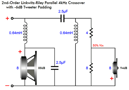
We see above the classic Linkwitz-Riley 2nd-order two-way crossover, with the tweeter getting a -6dB padding network made up of two resistors. The next step is to apply my enhancement:
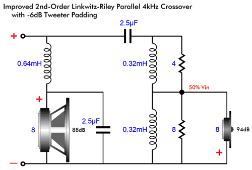
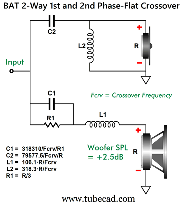
Two 0.32mH inductors rather than one 0.64mH inductor. The result is greater protection for and performance from the tweeter. The math is simple: the top inductor's value is equal to the original single inductor's value against the top resistor's value divided by the tweeter's impedance, while the bottom inductor's value equals the original single inductor's value minus the top inductor's value. We can take my phase-flat passive crossover from Post 624:
and to which we add my improved tweeter-inductor-shunting technique from Post 612 .
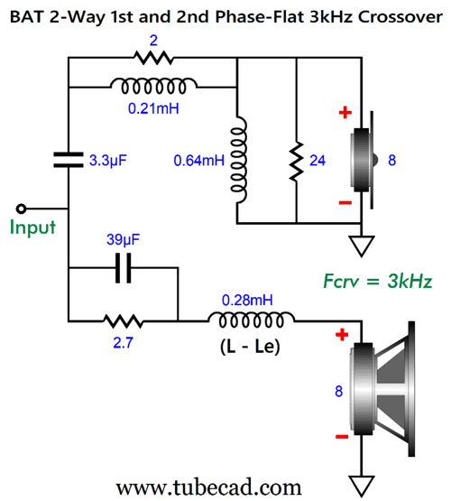
Rather than hunt down a woofer that offers an SPL/W 2.5dB greater than the tweeter, we pad with the 2-ohm and 24-ohm resistors the tweeter's input signal by -25dB. The two tweeter inductors add up to a total of 0.85mH. [Be sure to see Post 632, for further enhancements to this topology.] As for last year's other major theme, output-stage harmonic structure with single-ended versus push-pull, I have several new ideas for 2026.
The 70s Club Okay, isn't that AI-generated image great? I think so. (Other than his right possessing more than five fingers. AI believes that sexadactyly or hexadactyly is far more common than it is.) Here is another gem, but with the idea of encasing an hourglass within a vacuum tube envelope, but in another style, i.e. as 1940's photo:
Sadly, the AI trainers are woefully remiss in their duties, as AI has no idea what a 300B and 845 tubes look like, as nothing I could do could force the hourglass inside their glass envelopes. Here are some other AI wonders, click on an image to see its enlargement.
M O R E
More CCDB Buffers
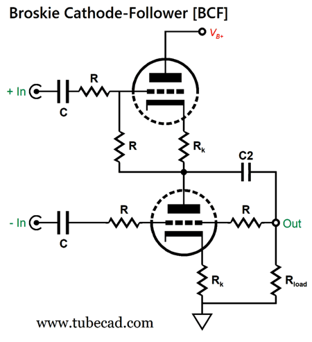
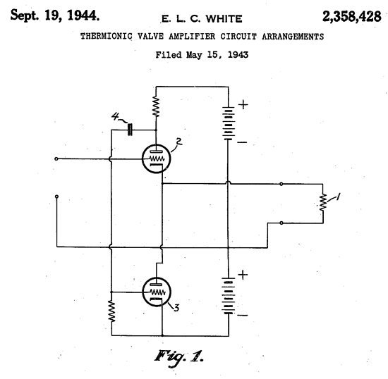
The history behind the BCF is interesting, back in the mid-1990s, a French recording engineer emailed me, asking if it was possible to devise a tube-based circuit to replace an audio isolation signal transformers, as he complained that one transformer in the signal path wasn't too bad, but when there were three or more, the signal quality degraded due to the successive and compounding truncated signal bandwidths. (Actually, he was French-speaking, but might have been from Belgium or Switzerland; if so and if you are reading this, my apologies.) My first effort was complicated and required many triodes. I discovered the solution by working backwards, i.e. by starting at the output and working to the input, which is how I design power amplifiers. I imagined forcing a positive pulse into the circuit's output and having both triodes respond equally to the disturbance. Having all resistors marked "R" equal the same resistance while having the balanced inputs grounded, met this condition. Next, I had to ensure a high CMRR. I now imagined both inputs receiving the same input signal in the same phase, while the output was shorted to ground. If a high CMRR is to be achieved, both triodes must alter their current conduction in phase and in amplitude, i.e. in unison. They did. From post 584 :
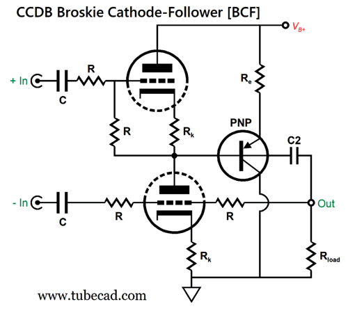
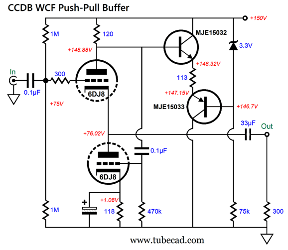
In other words, the BCF worked wonderfully. (By the way, as I have stated many times before, creating a great but confoundedly complicated circuit is easy; if nothing else, brute force and huge expense comes to the rescue. Creating a supremely simple but great circuit is near impossible, as the universe fights against us hard.) Okay, back to the problem of how to force constant-current draw conduction upon the BCF, in SPICE simulations, I discovered if the BCF held two 6DJ8 triodes with an idle current of at least 5mA, and with an external load impedance of no lower than 47k, we needn't bother. Why not? The BCF's push-pull, class-A operation effectively doubles the external load impedance, so a 47k load appears as 94k load to the circuit. Well what about a 10k load, as some solid-state power amplifiers present a 10k input impedance? We can add a PNP transistor and emitter resistor.
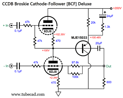
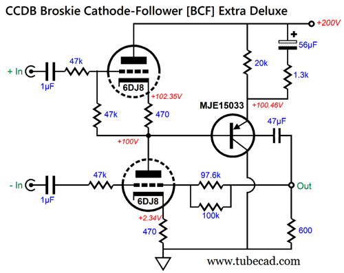
My guess was that with an external load impedance of 10k, resistor Re should equal 20k. In SPICE simulations, however, 27k proved optimal. On the other hand, if the load is a crushing 300 ohms, we must get fancier by adding an additional resistor and capacitor.
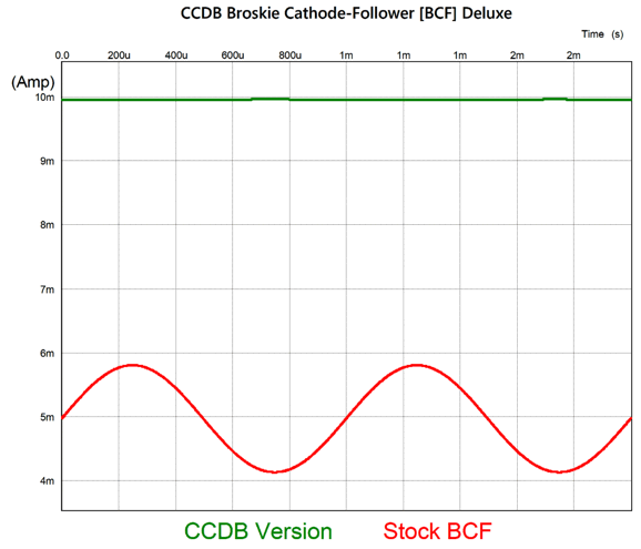
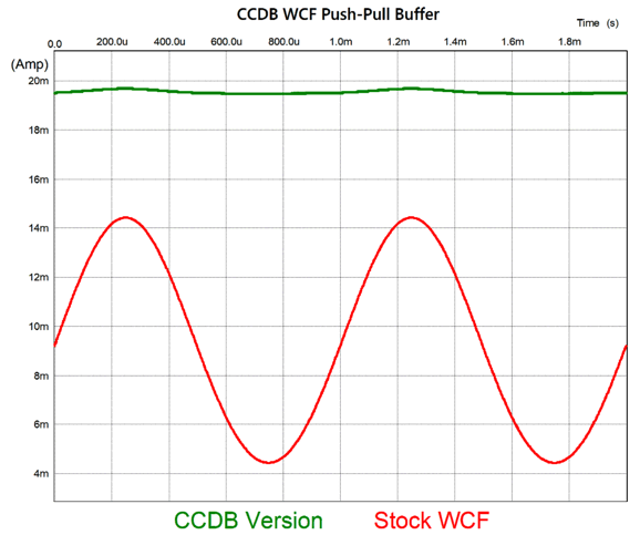
Note the two resistors in parallel. In theory, the Re resistor should equal half the B+ voltage divided by the triode's idle current, e.g. 100V/0.005A = 20k in this example; and the added resistor should equal twice the external load impedance, while the added capacitor should match the output coupling capacitor's value. In SPICE simulation, however, the 1.3k resistor and 24µF capacitor delivered the best results. Speaking of results, here is a SPICE-generated graph that shows the stock BCF current conduction in red and the CCDB version in green, with 1Vpk into the 600-ohm load at 1kHz.
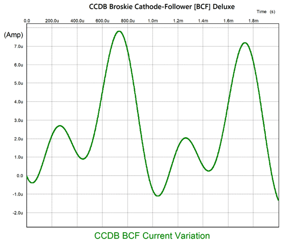
If we do a closeup of the CCDB's current variation, we see the following:
Dang close to no perturbation in current flow, don't you think? The CCMR proved excellent.
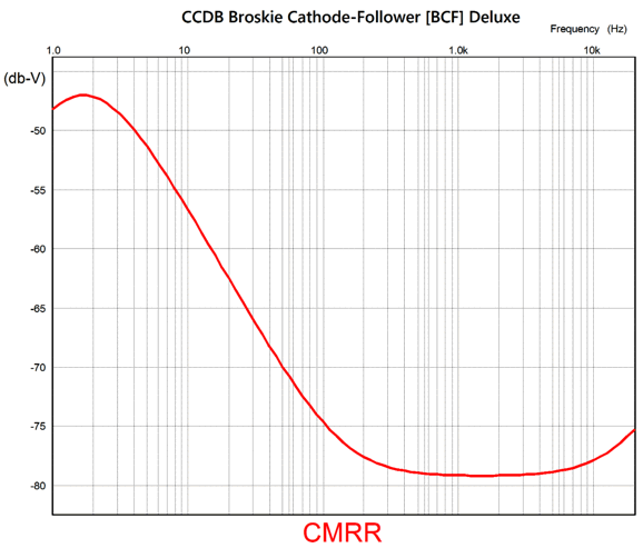
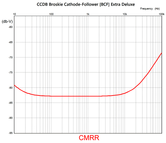
Although already very good, I wondered if it could not be improved. It could.
The larger capacitor values further extend the CMRR in the low frequencies and decrease the mid-band frequencies as well.
The important 50Hz and 60Hz frequencies are now reduced below -80dB.
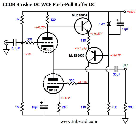
A CCDB White Cathode Follower
Since all the current flowing through the top triode also flows through the current-sense resistor atop the triode, we can monitor the current conduction with this resistor. Here was my first attempt to create a CCDB White cathode follower:
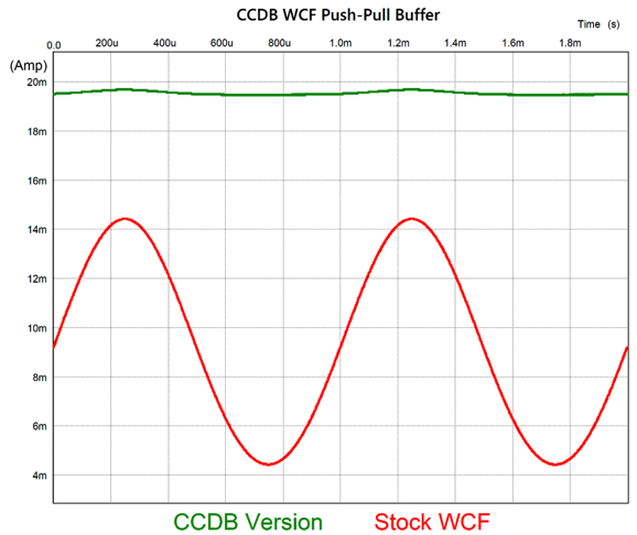
The 113-ohm resistor between the two transistors sees much the same voltage-drop variations that the 120-ohm current-sense resistor experiences, but in current anti-phase. In other words, if the 120-ohm resistor sees a greater voltage drop, the 113-ohm resistor sees lesser voltage drop—and vice versa. With two cycles of 3Vpk at 1kHz into a 300ohm load, the following graph shows the varying current conduction between a stock White cathode follower and the CCDB version.
That's some improvement, as we went from a peak-to-peak current-variation swing of 10mA to only 0.2mA, a fiftyfold reduction in current-flow variation. As I looked at the schematic, I was reminded of a DC-coupled version of the White cathode follower that I had invented over 30 years ago.
No more internal 0.1µF coupling capacitor, as the signal created by the variation in voltage drop across the 120 current-sense resistor is now DC relayed to the bottom triode via the two transistors and two 1k resistors. All I had to do was lower the two 1k resistors in value and get two features, constant-current-draw and internal dc coupling, for the price of one feature.
I had to fiddle with the resistor values to get the best results, but it was worth it, as the performance improved.
The peak-to-peak current-conduction variation has now fallen to 0.09mA. By the way, a few years after coming up with the DC-coupled White cathode follower circuit, I modified it thus:
Just for giggles, I decided to run a distortion test in SPICE on my old variation just to see how well it performed working into the 300-ohm load (Sennheiser headphones impedance).
Not bad at all, as the THD is about 0.1%.
CCDA SRPP
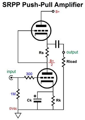
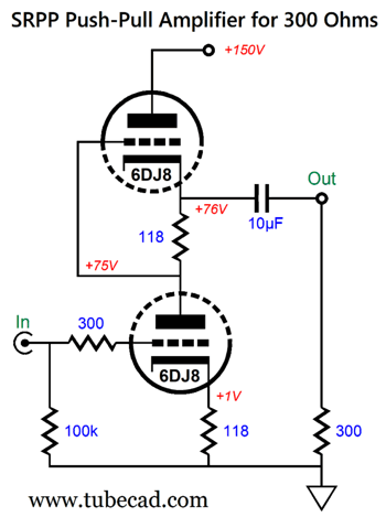
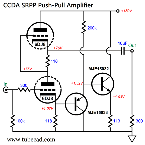
When an SRPP is optimized for a low-impedance load, the peak output is realized and the distortion falls to its lowest. On the other hand, the SRPP's output impedance is nowhere as low as that offered by the cathode follower, White cathode follower, Broskie cathode follower, or SRCFPP . This makes perfect sense, as the triodes used only have so much transconductance to offer us. Where the buffer circuits use all of the transconductance to deliver a low output impedance, the SRPP uses the transconductance to create signal gain, as well as push-pull operation, leaving very little transconductance left to deliver a low output impedance. Mind you, a failing in one scenario often provides a benefit in a different situation, much like an instinctively murderous man making a stellar war hero or a born thief being too lazy to thieve. Here is an example SRPP circuit that has been optimized to drive a 300-ohm load that makes this point for me.
Note the seemingly too small output coupling capacitor value of just 10µF. The formula for an output coupling capacitor is simple: C = 159155/R/F where C is in µF and R is the load impedance and F is the -3dB cutoff frequency. If we do the calculation, the 10µF capacitor should produce a low-frequency cutoff of 53Hz. But in this circuit, the real cutoff frequency is closer to 9Hz. Why the discrepancy? The SRPP's high output impedance (1470 ohms) must be added to the load resistance. In fact, if we limit the low-frequency bandwidth to 20Hz, a 4.7µF coupling capacitor proves sufficient. Since the top and bottom triode function in current anti-phase to each other, their sum would equal the idle current if they were in parallel and not in series with each other. We know that when the SRPP sees a positive voltage pulse at its grid, the bottom triode will draw more current, while the top triode draws equally less current. Well, what if we add a current mirror to the bottom triode, one that terminates into the B+ voltage, thereby making up for the top triode's weakened current flow, but at the cost of doubling the idle current of the entire circuit? A bargain, in my opinion, as a wildly varying current flow from a circuit effectively makes the power-supply reservoir capacitor an unintended coupling capacitor. Think about it, many will spend hundreds of dollars on the fanciest boutique-brand output capacitor, but ignore the power supply capacitor, falsely believing that it is not in the signal path. But, John, it isn't in the signal path. Not directly, true; in terms of chain of signal current flow, however, it certainly is in the path. On the other hand, if the current flow remains constant, the power supply capacitor and series RC resistor fall out of the equation. Here is an analogy: imagine that you are holding a rope that meets a pulley attached to tree's limb and holds up a bucket of water. Your task is to hold the bucket still, so a friend can photograph it. Easy, right? It is, if a flock of big birds do not land on the bucket's rim and sip water before kicking off in flight. Constant-current draw is like having no birds. Or, to switch metaphors, smooth roads to not beg for good shock-absorbers.
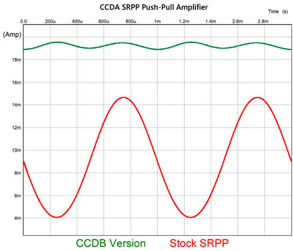
The PNP transistor is used to provide a positive voltage displacement and to unload the cathode resistor of too high an extraneous load impedance. The NPN transistor follows the cathode's voltage variations, which it imposes on the 113-ohm emitter resistor. In short, this is a current mirror. How well does this scheme work? Here are the results from SPICE:
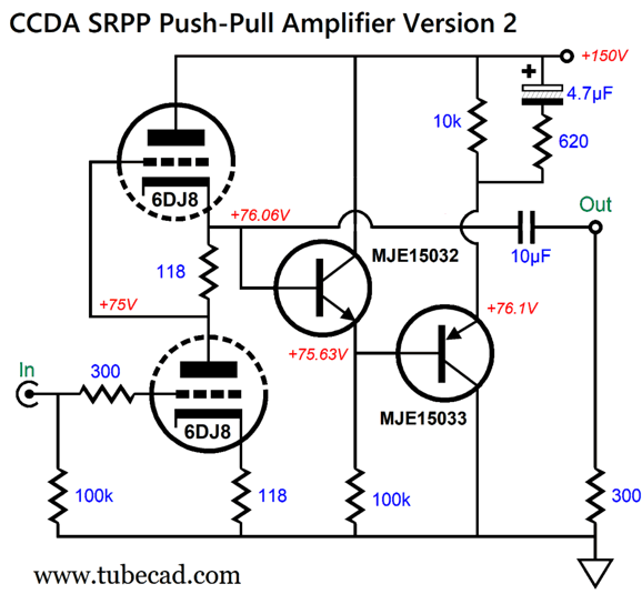
Note that the CCDA version's conduction is in anti-phase to that of the SRPP. If the SRPP's push-pull operation were more linear, the 2nd harmonic superimposition would disappear. Still, the peak-to-peak current variation is only 0.37mA, a fraction of what it is with a stock SRPP. I wondered if I attached the CCDA circuit to the output, rather than the bottom cathode, would the current draw flatten further.
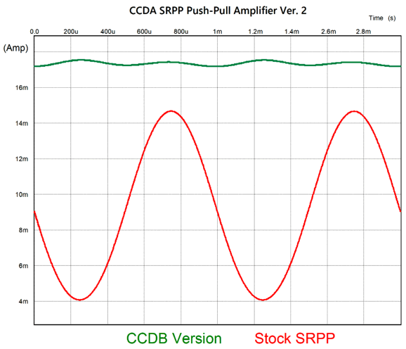
I quickly discovered from my inspection of the resulting distortion graphs without the PNP transistor that the PNP transistor was definitely needed to buffer the output from the NPN transistor's base impedance. (Unlike a triode's grid, a transistor's base requires some work to be driven. Moreover the SRPP's high Zo is easily dragged down.) Sadly, the results were not much better, if at all better. Nonlinear is nonlinear.
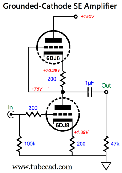
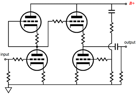
Before leaving the SRPP, we should look at its brother circuit that is entirely single-ended, with zero pushing and pulling.
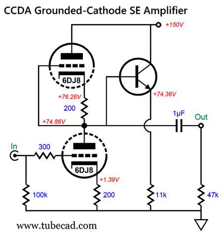
The tube-based portion of this circuit is simply a grounded-cathode amplifier with an active plate load.
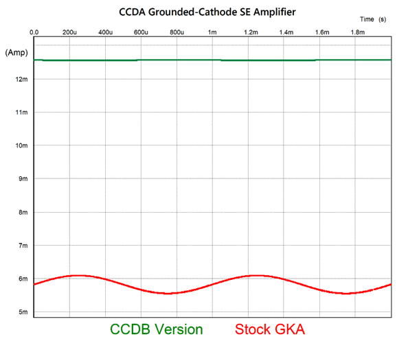
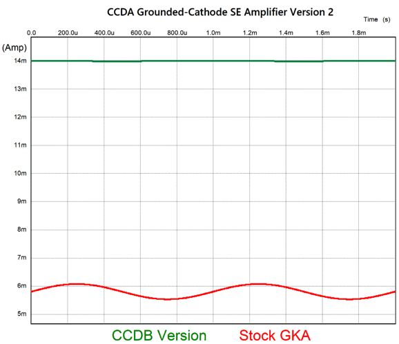
It has been called a symmetrical or balanced amplifier. The top triode and its cathode resistor together present a load impedance equal to rp + (mu + 1)Rk. The 11k emitter resistor comes close to matching this impedance, which creates a CCDA circuit. With 3Vpk of output at 1kHz into 47K:
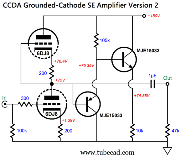
The peak-to-peak current variation is only 4µV. Remembering how the SRPP's output was perturbed by the NPN transistor's base impedance, I decided to try the half a diamond variation.
Note the 10k resistor in place of the 11k resistor. Why? The 105k resistor undoes the NPN transistor's anti-phase current conduction. Here is the SPICE-generated current graph:
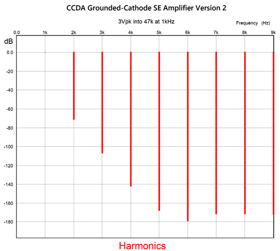
The current variation is halved. The distortion, by the way, is quite low, mostly due to the relatively high idle current and the balanced loading. With 3Vpk of output into the 47k load at 1kHz, we get this Fourier graph.
Extremely fine. By the way, the SRPP's harmonic structure under the same conditions was also fine, but not quite as fine at this circuit's, which is just one reason that I didn't use the SRPP as the Aikido amplifier's input stage.
Mind you, many look at the schematic above and see an SRPP circuit.
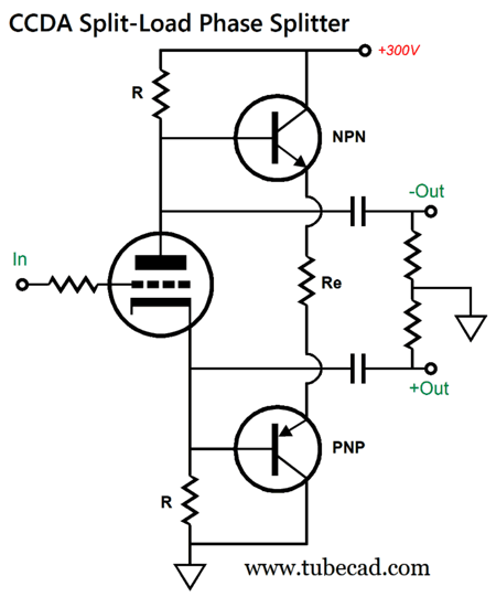
CCD Split-Load Phase Splitter
The shared emitter resistor should be close to twice the resistance of either the plate or cathode resistor, R. With my Aikido-Mojo design of the split-load phase splitter, the emitter resistor turned out to be a much higher in value.
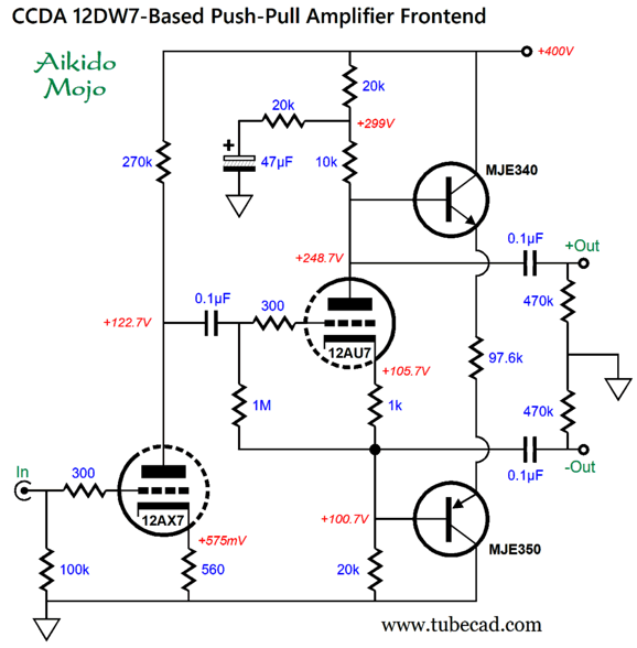
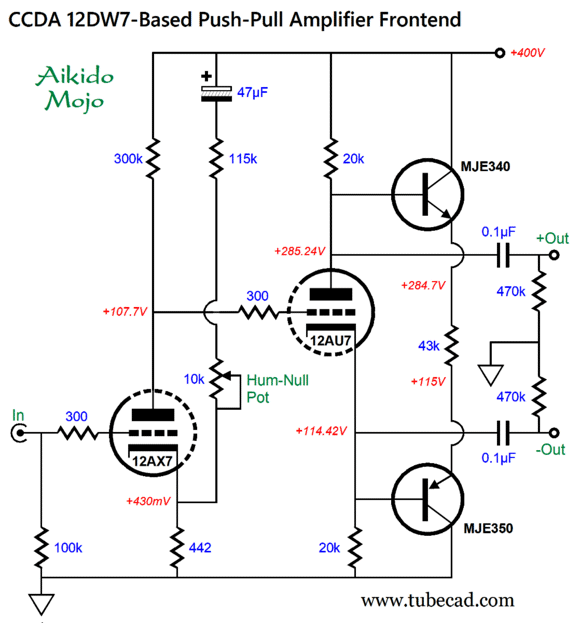
The point behind the elaborate plate load for the 12AU7-based split-load phase splitter is to ensure that both outputs share the same amount of power-supply noise and in phase, so that the push-pull output stage can differentially ignore the ripple. Surprisingly enough, this technique also lessened the current-draw variation under signal, so that the 97.6k resistor worked best in SPICE simulations. If no negative-feedback loop is planned on being included, the following design retains more plate voltage for the split-load phase splitter.
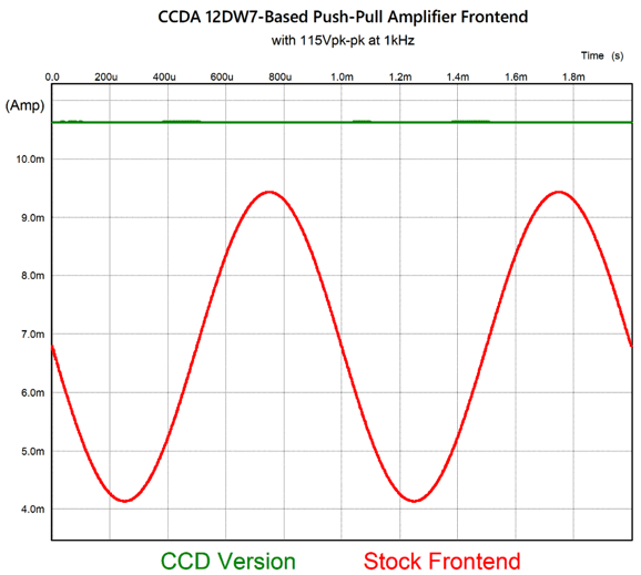
The potentiometer allows for tube variation and aging. The 43k resistor should be rated for 5W of dissipation, as at startup, and when the tube is missing from its socket, this resistor will effectively see the entire B+ voltage. Here is the graph for this last design:
In a word, nice! Not bad for a guy in his seventies.
Music Recommendation:Hok-Man Yim, Poems of Thunder //JRB
AI Summary The document, "Post 631," dated January 21, 2026, provides a detailed review of the author's work in 2025 and introduces new ideas for 2026. Key points include:
The document is a mix of technical insights into audio design, personal reflections, and a music recommendation.
Did you enjoy my post? Do you want to see me make it to post 1,000? If so, think about supporting me at Patreon.
User Guides for GlassWare Software
For those of you who still have old computers running Windows XP (32-bit) or any other Windows 32-bit OS, I have setup the download availability of my old old standards: Tube CAD, SE Amp CAD, and Audio Gadgets. The downloads are at the GlassWare-Yahoo store and the price is only $9.95 for each program. So many have asked that I had to do it. WARNING: THESE THREE PROGRAMS WILL NOT RUN UNDER VISTA 64-Bit or WINDOWS 7, 8, and 10 if the OS is not 32-bit or if it is a 64-bit OS. I do plan on remaking all of these programs into 64-bit versions, but it will be a huge ordeal, as programming requires vast chunks of noise-free time, something very rare with children running about. Ideally, I would love to come out with versions that run on iPads and Android-OS tablets.
|
I know that some readers wish to avoid Patreon, so here is a PayPal button instead. Thanks. John Broskie
John Gives
Special Thanks to the Special 89 To all my patrons, all 91 of them, thank you all again. I want to especially thank
I am truly stunned and appreciative of their support. In addition I want to thank the following patrons:
All of your support makes a big difference. I would love to arrive at the point where creating my posts was my top priority of the day, not something that I have to steal time from other obligations to do. The more support I get, the higher up these posts move up in deserving attention.
If you have been reading my posts, you know that my lifetime goal is reaching post number one thousand. I have 375 more to go. My second goal was to gather 1,000 patrons. Well, that no longer seems possible to me, so I will shoot for a mighty 100 instead. Thus, I have just 9 patrons to go. Help me get there. Thanks.
New URL of the GlassWare website |
||||


.png)
.png)
%20Fourier.png)


| www.tubecad.com Copyright © 1999-2026 GlassWare All Rights Reserved |