| John Broskie's Guide to Tube Circuit Analysis & Design |
| January 31 2026 | Post Number 632 |
||||
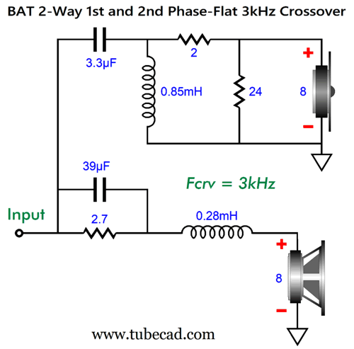
Return of the Crossovers
The tweeter's SPL has been reduced by 2.5dB due to the 2- and 24-ohm resistors, thereby undoing the-2.5dB insertion loss that the woofer undergoes. And the same topology, but with the following enhancement:
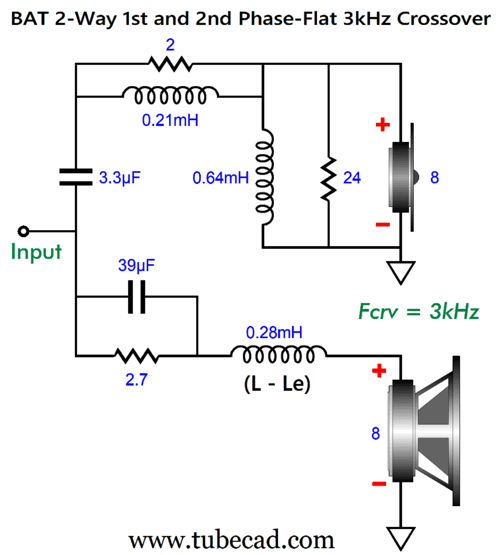
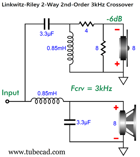
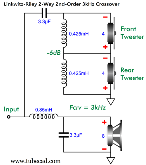
The 0.85mH inductor of the original crossover has been split into two and abides by the same ratio as the AC voltage attenuation, i.e. 75%. (The 24-ohm resistor and 8-ohm tweeter create a combined resistance of 6 ohms.) Now, the tweeter sees a dead short at DC, instead of the 1.85 ohms of the original design. Well, this schematic got me thinking about the case wherein the tweeter gets -6dB of attenuation. I will use the familiar Linkwitz-Riley 2nd-order topology:
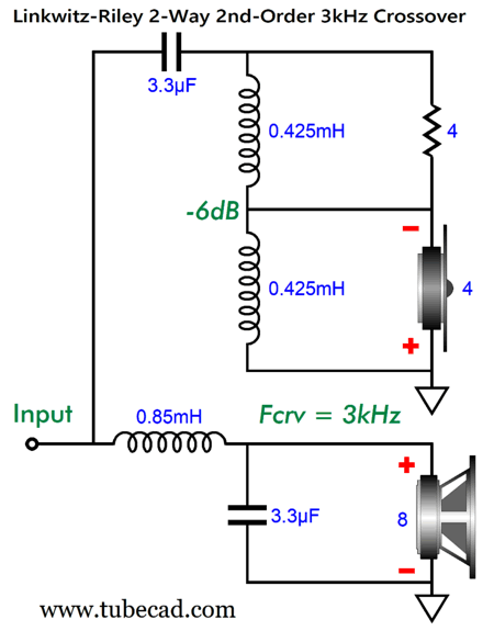
(Note the phase reversal on the tweeter; the Linkwitz-Riley crossover is not phase-flat.) The 8-ohm resistor shunting the 8-ohm tweeter creates a 4-ohm resistance. Well, what if we used a 4-ohm tweeter instead and lose the 8-ohm resistor?
The tweeter would still be attenuated by -6dB. Beyond the savings of the resistor, 4-ohm tweeters usually sound better than their 8-ohm equivalent. Why? Less mass. The 4-ohm version of the tweeter holds a voicecoil wire half the length of the 8-ohm version. (If you work out the math, you soon realize that moving a tweeter's dome back and forth 20,000 times a second produces an insane amount of G–forces. The higher the mass, the harder this task becomes.) Okay, what if we also replace the remaining 4-ohm resistor with another 4-ohm tweeter?
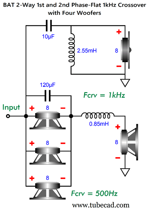
Why? Perhaps you have noticed that many of the most highly esteemed (and expensive) loudspeakers now sport rear-firing tweeters. The reason behind this added expense and hassle is that the sound improves. Back in the previous century, listening tests were conducted to discern which loudspeakers sounded best. One finding was that the more closely the reflected sound's bandwidth matched the direct sound's bandwidth, the higher the loudspeaker approval rating. (Of course, a rear-firing tweeter on a bookshelf loudspeaker or a corner horn loudspeaker will not do any good.) This finding helps explain why electrostatic and dipole planar loudspeaker are so valued. Next, my attention was drawn to the BAT phase-flat crossover's use of a 2.7-ohm resistor in the following schematic.
This resistor causes the -2.5dB reduction in the woofer's SPL. Well, what if we replace this resistor with three woofers? Three 8-ohm woofers equals 2.6666 ohms of impedance. (The use of the 2.7-ohm resistor was an example of close-enough-for-government work.)
The added woofers could be mounted on the rear of the loudspeaker cabinet, thereby not only undoing the low-frequency diffraction loss, but also preventing the enclosure from rocking back and worth due to the front-firing woofer's excursions.
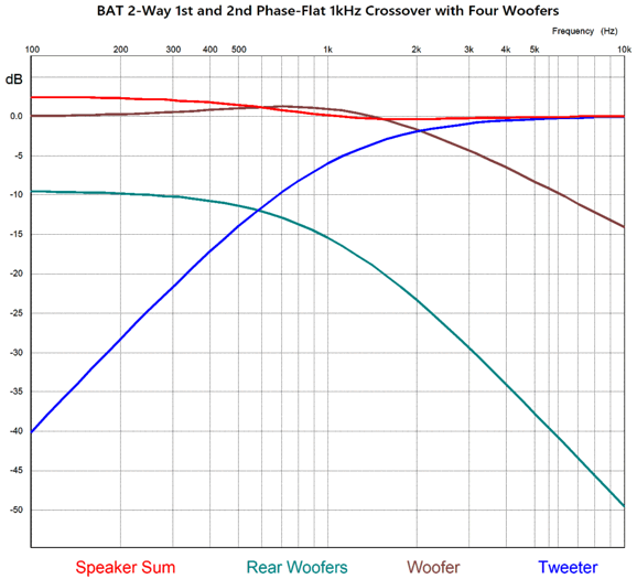
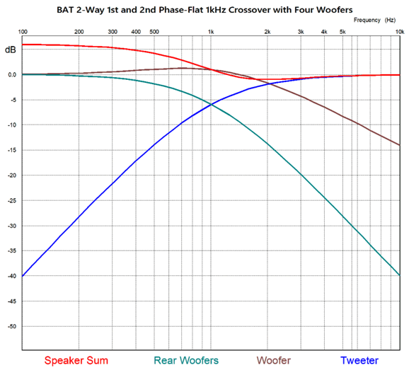
The added woofers only get a fraction of the signal that the front-firing woofer sees.
This SPICE-generated graph shows the electrical signals delivered, but not the actual acoustical output, as the three added woofers will offer a 9.5dB boost in SPL due to the threefold increase in radiating surface area. Speaking of reality, the tweeter must offer 2.5dB less SPL than the front woofer. The modified following graph is closer to reality.
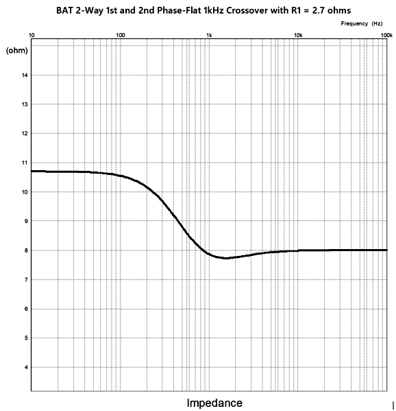
Better, but not perfect, as I do not believe that the dip in the midrange will actually obtain. Why not? The rear-firing woofers' directivity at high-frequencies and the enclosure width are enough to prevent those higher frequencies from meeting up with the front sound radiation. We do get the +6dB boost in the low-frequencies, but since the loudspeaker shifts 180-degree radiation at higher frequencies to 360-degree radiation at low-frequencies, it incurs a -6dB loss at low-frequencies. In other words, flat frequency response results, as long as the loudspeaker is relatively narrow and tall and stands well away from the back wall. I envision using four small woofers or fullrange drivers, say 4in to 5in in a cabinet 8-inches square by three to four feet tall. The tweeter could be an AMT or planar driver. So have I ringed the last drop from this crossover topology? Not likely. An odd feature (or liability) of this topology is that it creates a non-flat impedance plot, as the impedance rises at low-frequencies.
I wondered if we could not flatten the impedance curve and gain some rear-firing woofer action at the same time. The impedance rises to 2.7 + 8 ohms (10.7 ohms) at low-frequencies, which could be brought back down to 8 ohms by shunting the crossover with a 31.7-ohm resistance at low-frequencies. Well, a 32-ohm woofer is close enough in impedance, but not made. Two 16-ohm woofers, which are made, could be placed in series, but I had a far more interesting idea: a transformer and single added woofer.
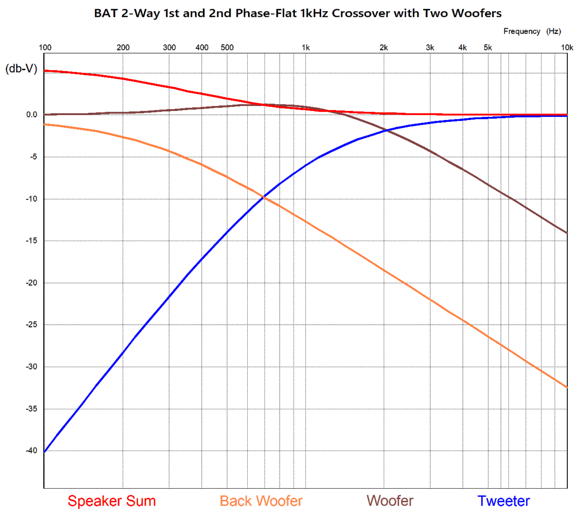
The transformer is simply a cheap toroid with a 50VA rating. Toroidal power transformers deliver wide enough bandwidth to be used as step-up transformers in electrostatic loudspeakers. In other words, no $$$ fancy audio-grade transformer is needed. Note the 255Hz cutoff frequency that the 4-ohm rear-firing woofer gets. With a winding ratio of 2.8 to 1, we get an impedance ratio of 8 to 1, so the 4-ohm load is reflected to the transformer's primary as 32 ohms. The added 4-ohm woofer only sees 35% of the signal that the front-firing woofer sees, resulting in a -9dB loss. But we must add the +6dB boost if the rear woofer is located near the floor. In addition, we can pick a 4-ohm woofer with greater or less SPL. Here is the SPICE-generated graph:
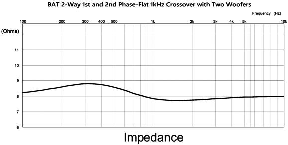
Note that there's no dip in the midrange frequencies. Here is the impedance plot:
Okay, what's not to like about this new arrangement? One danger is that with direct-coupled power amplifiers (i.e. just about every solid-state power amplifier), the toroid's primary resistance might be only a fraction of an ohm, which means that any DC offset becomes hugely more dangerous. Of course, capacitor-coupled OTL amplifiers and transformer-coupled solid-state would be safe. Another possible issue is that the 4-ohm woofer's frequency response may differ too greatly from the 8-ohm woofer's. We could use two 8-ohm identical to the front-firing woofer in parallel on the rear, or we could use only one identical woofer on the rear, but with a toroid transformer with a winding ratio of 2:1, which implies an impedance ratio of 4:1, making the back 8-ohm woofer appear as a 32-ohm load to the rest of the crossover.
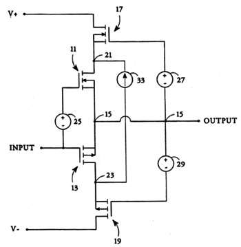
Nelson Pass's Floating Power Supply OPS From my Post 554: Today, high-current, low-voltage switch-mode power supplies are both common and cheap—sadly, most are made in China, so tariffs might apply. Still, even a tariff-inflated price is dirt cheap compared the cost of a huge power transformer and conventional power-supply parts, such as massive reservoir capacitors. The two center output devices idle at a huge single-ended current flow, say 2A to 5A, while the top and bottom devices idle at a fraction of that heavy current, say 100mA. Let's compare Pass's designs to a single-ended power buffer that idles at 3.2A.
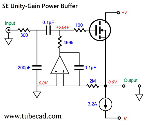
The maximum theoretical efficiency for a constant-current source loaded single-ended output stage is 25%. Of course, reality will disappoint. An output current peak swing of 3A implies a peak power output of 36W into an 8-ohm load. It also implies a peak output voltage swing of ±24Vpk, which further implies a bipolar power supply rail voltages of at the very least ±26Vdc, but ±28Vdc would prove more likely. Now, 3.2A against 56V equals 179.2W of heat dissipation at idle, yielding only 20% efficiency. By the way, the output stage cools at full output, as the loudspeaker sucks up 36W of power, leaving only 143.2W for the output stage to dissipate. Still, that's a lot of heat, which further implies a huge heatsink and power transformer. In contrast, the Pass arrangement is far more energy frugal. Let's examine a possible inner floating power supply and single-ended power buffer.
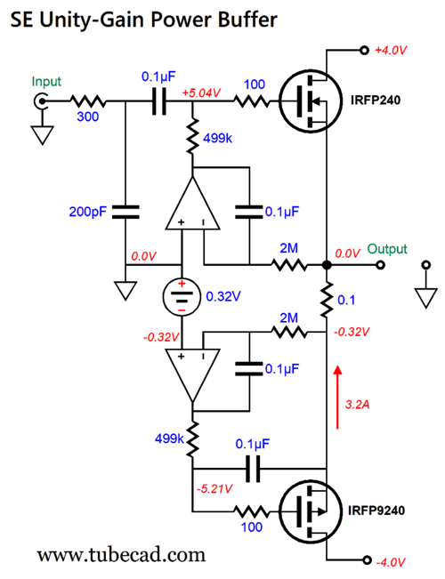
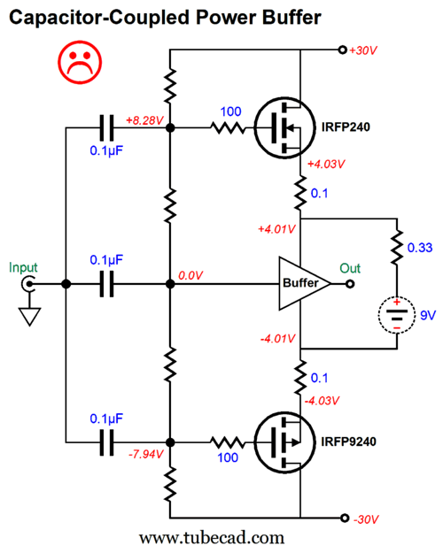
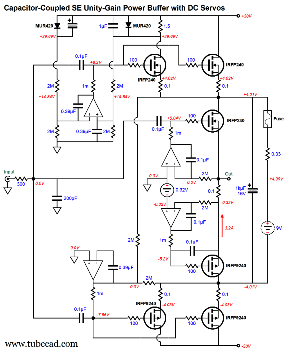
Yes, it looks like a push-pull buffer, but it is an entirely single-ended affair, as the IRFP9240 P-channel MOSFET functions as a constant-current source. (Note where its coupling capacitor terminates, it's not the input signal, but the output.) The wonderful thing about MOSFETs is their super high input impedance at DC, unlike bipolar transistors. In other words, the 0.1µF coupling capacitors are sufficient to extend the bandwidth down to sub-audible frequencies.
Next, let's plug this circuit into the Pass topology:
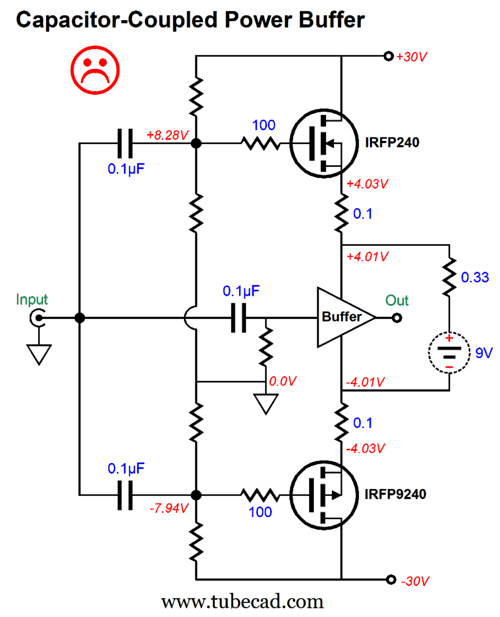
Note that the output stage drives the cascode MOSFETs via the two zener diodes. The extra load presented, 1k, by this bias arrangement is trivial compared to the 8-ohm loudspeaker, but what does worry me is that the single-ended buffer's departure from the input signal will also be imposed upon the cascode MOSFETs' output. This got me thinking about adding two extra input coupling capacitors and letting the input signal drive the cascode MOSFET directly.
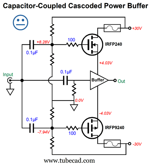
No happy face. Getting the exactly right resistors values to eliminate a DC offset would be next to impossible. The bigger problem with this arrangement is that if a power-supply-rail fuse opens, the output will slam to the other lower rail voltage. Not good. The following workaround is a little better, but not perfect.
The better workaround is to attach the resistors to the bipolar power supply before the fuses.
But even this workaround didn't earn a happy face, as it assumes a regulated bipolar power supply. If the bipolar power supply is not regulated, then a small shift in wall voltage results in huge variations in idle current flow for the cascode MOSFETs.
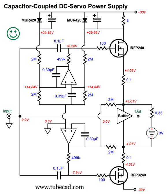
The graph only shows a narrow range ±2% variation in wall voltage. At one extreme the cascode MOSFETs cease to conduct, at the other extreme they melt. This problem got me thinking about using OpAmps to auto-bias the cascode MOSFETs. I then realized that I could also use an OpAmp to auto-center the cascode MOSFETs.
The top OpAmp sets the cascode MOSFET idle current by monitoring the voltage drop across the 3-ohm resistor. (This resistor need not be a high-wattage type, as the worst case scenario is that it experiences a 0.6V voltage drop, as the resistor is shunted by the MUR420 rectifier that effectively acts as a 0.6V zener.) The bottom OpAmp centers the cascode MOSFETs. All the 2M resistors must be tight tolerance types, say at least 1%, preferably 0.1% types.
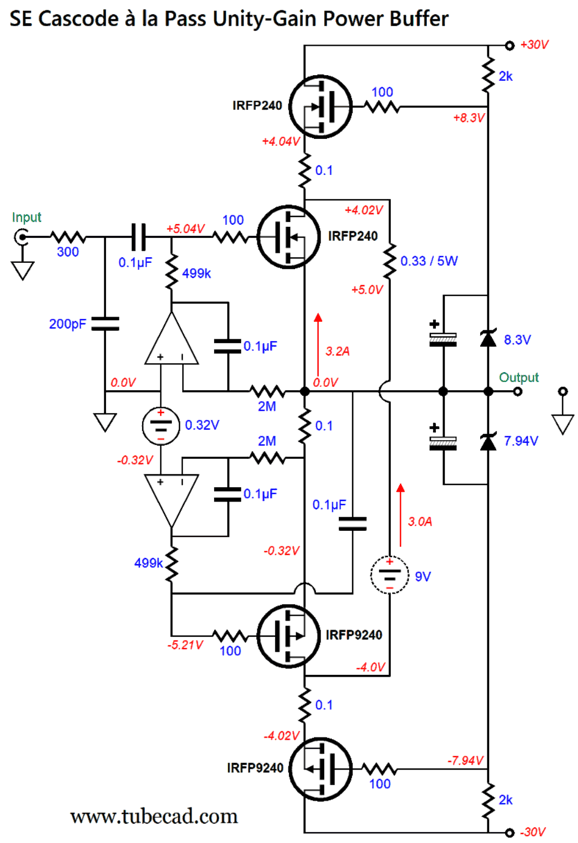
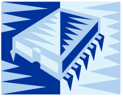
A dual-amplifier OpAmp should not be used, unless it is a unity-gain high-voltage type. Instead, single-amplifier unity-gain OpAmps should be used, with the top OpAmp's power-supply pins to the 30V power-supply rail and the ground, making effectively a ±15Vdc bipolar power supply for the OpAmp. Likewise, the bottom OpAmp could attach to ground and the -30V power-supply rail—if and only if the OpAmp allowed an input voltage equal to the positive power-supply rail voltage, which in this case 0V, but effectively +15Vdc. Device data PDFs are you best friend here. By the way, all the OpAmps can run off ±18Vdc bipolar power supply rails. An additional by the way, the two rectifiers should be mounted together, touching intimately, so that they can heat equally, and thus establish the same voltage drop. Okay, now we can see the full schematic:
The cascode MOSFETs have been doubled up to reduce individual dissipation and excessive voltage drop across the 0.1-ohm source resistors. The floating 9V power supply gets an RC capacitor in the added 1kµF electrolytic capacitor, which will banish the high-frequency ripple from the switch-mode power supply. Note the change in the servo resistor values, 1M versus 499k. Why? If the center power buffer is DC coupled at the input, we use 499k resistors, but with a coupling capacitor, we use 1M resistors, which creates a high-pass filter Q of 0.5.
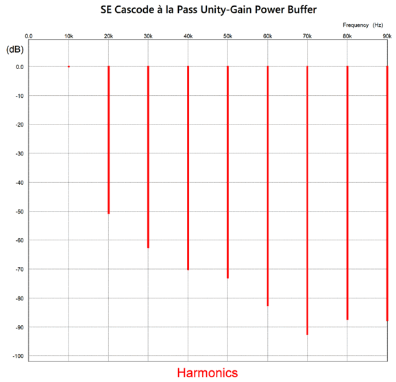
The 300-input resistor represents the output impedance from the tube-based input stage not shown (an Aikido gain stage with a 12AT7 or 12AX7 or 5751 input tube and an ECC99 output tube). The center IRF MOSFETs draw 3.2A at idle, while the cascode MOSFETs draw 50mA each. The center power buffer dissipates 25.7W at idle, while the entire power buffer dissipates 34.2W. Not bad, especially when we consider the single-ended harmonic structure of the output. Speaking of which here is the SPICE-generated Fourier graph for 36W of output at 10kHz into an 8-ohm load, without the tube-based input stage.
What's not to like here? With a test frequency of 1kHz instead of the 10kHz, the results are even more impressive. Remember, there is no negative feedback loop in use in this design. (The DC servos do not count, as they are only concerned with DC voltages.)
Music Recommendation:Paloma Dineli Chesky's Memory
Also check out her album from 2022, Soul on Soul, where you get to hear her sing the following classics, "Hound Dog" and "Ode to Joy," but not the words used by Beethoven and written by Schiller, but these by Henry van Dyke, "The Hymn of Joy:"
This is apparently the cleaned up alternative version sung in churches to Beethoven's melody, leaving behind Schiller's original less church-worthy lines, such as:
//JRB
AI Summary The document covers two main topics: loudspeaker crossover design and Nelson Pass's floating power supply topology. Additionally, it includes a music recommendation. Key Points:1. Loudspeaker Crossover Design:
2. Nelson Pass's Floating Power Supply Topology:
3. Music Recommendation:
Did you enjoy my post? Do you want to see me make it to post 1,000? If so, think about supporting me at Patreon.
User Guides for GlassWare Software
For those of you who still have old computers running Windows XP (32-bit) or any other Windows 32-bit OS, I have setup the download availability of my old old standards: Tube CAD, SE Amp CAD, and Audio Gadgets. The downloads are at the GlassWare-Yahoo store and the price is only $9.95 for each program. So many have asked that I had to do it. WARNING: THESE THREE PROGRAMS WILL NOT RUN UNDER VISTA 64-Bit or WINDOWS 7, 8, and 10 if the OS is not 32-bit or if it is a 64-bit OS. I do plan on remaking all of these programs into 64-bit versions, but it will be a huge ordeal, as programming requires vast chunks of noise-free time, something very rare with children running about. Ideally, I would love to come out with versions that run on iPads and Android-OS tablets.
|
I know that some readers wish to avoid Patreon, so here is a PayPal button instead. Thanks. John Broskie
John Gives
Special Thanks to the Special 91 To all my patrons, all 91 of them, thank you all again. I want to especially thank
I am truly stunned and appreciative of their support. In addition I want to thank the following patrons:
All of your support makes a big difference. I would love to arrive at the point where creating my posts was my top priority of the day, not something that I have to steal time from other obligations to do. The more support I get, the higher up these posts move up in deserving attention.
If you have been reading my posts, you know that my lifetime goal is reaching post number one thousand. I have 368 more to go. My second goal was to gather 1,000 patrons. Well, that no longer seems possible to me, so I will shoot for a mighty 100 instead. Thus, I have just 9 patrons to go. Help me get there. Thanks.
New URL of the GlassWare website |
||||


| www.tubecad.com Copyright © 1999-2026 GlassWare All Rights Reserved |