| John Broskie's Guide to Tube Circuit Analysis & Design |
| April 29 2026 | Post Number 637 |
||||
Special Thanks to
Balanced Hybrid Phono Preamps
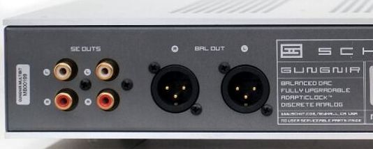
As a nod to those rare audiophiles and due to many DACs using an internal balanced two-DAC setup to gain an enhancement in noise reduction, balanced XLR outputs are often included along with the standard unbalanced RCA output jacks. I view these balanced outputs as a nice freebie. In addition, the phono cartridge, like the audio transformer and loudspeaker driver, is an inherently balanced-output device, as either end can be terminated into ground—or no end grounded directly. My inclination is to always examine potential exploitation of audio freebies. For example, when I look at the balanced XLR output jacks on the back of my DAC, I cannot help but think of possible uses from them in my otherwise unbalanced system, which includes single-ended power amplifiers. (I have even come up with a balanced input stage for a single-ended tube-based output stage.) Lately, the balanced nature of the phono cartridge has intrigued me enough to reexamine balanced phono preamplifiers—but with a different emphasis. But before going on to explain where that different emphasis falls, I will save myself some work by quoting myself from 27 years ago.
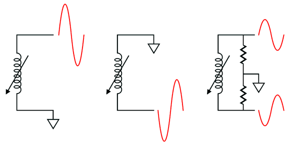
This article (I hadn't started using the post label yet) includes a fuzzy GIF image to show the essential balanced nature of a phono cartridge, which I have redrawn here:
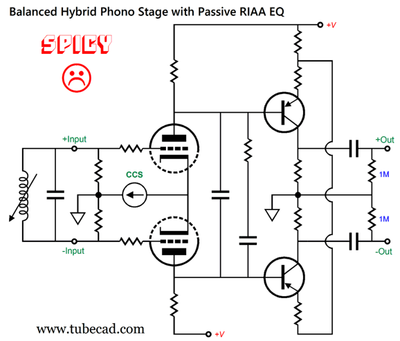
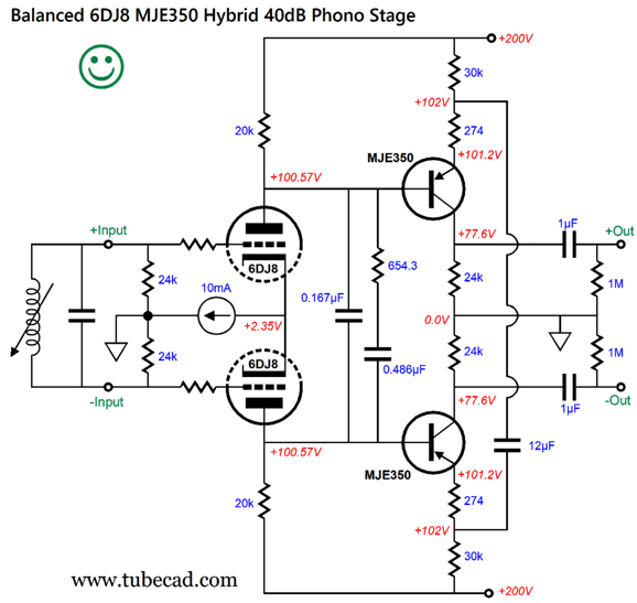
The cartridge's output signal doesn't care how you ground or don't ground it, something that cannot be done with an unbalanced signal. The rightmost setup is what we will use in a balanced phono stage. Returning to where my different emphasis falls, I like experimenting with absolute-phase reversal, as some music sounds better with the phase flipped one way or the other. In spite of my using single-ended power amplifiers, an unbalanced line-stage amplifier with a phase switch would be fun. (I built a headphone amplifier with this feature, and it was easy to use, as the short headphone cable kept me close to the switch.) This is where my new emphasis requires that the balanced output from a balanced phono preamp offers equally fine PSRR from each phase of the balanced output, as only one phase will be used at a time, so the CMRR of a balanced line-stage amplifier or a balanced power amplifier will not be there to clean up a poor PSRR from the phono preamp. No doubt, many of you have long accepted my obsession with seeking a great PSRR, but with phono preamps, this obsession is even more justified. A further demand I had was that I wanted to use as few tubes as possible. Why? Tubes are not getting any cheaper, and great-sounding vintage NOS tubes are rapidly being depleted. In other words, if the year were 1956, I would happily go tube extravagant; but as the year is 2026, a hybrid arrangement makes the most sense. My first topology layout worked great in SPICE simulations, but would probably bomb in reality. Here it is:
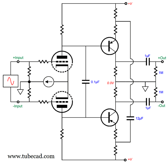
The high-transconductance input triode-based differential amplifier develops some gain, and then a passive RIAA equalization network counters the curve imposed on the LP, and the transistor-based second differential amplifier provides the remaining required signal gain and filters away the extremely poor PSRR noise from the first-stage's output. I just realized that many could not see the second differential amplifier in this schematic, so I drew it again.
It's the exact same topology, but the altered drawing should make the transistor-based output differential amplifier more obvious. Okay, returning to the sad face, the big problem is that the tube-based input stage must hold truly matched triodes, which is not likely in reality. Even a small mismatch will cause differing DC plate voltages, which in turn will cause the transistor-based differential amplifier to latch up and shutdown one of its two phase outputs. Not good. Workarounds, such as adding a potentiometer to span the cathodes with the scraper attaching to the constant-current source, are a pain. (Besides, I never like to have DC current flow through a potentiometer scrapper.) My workaround was to accept the reality of poorly DC-matched dual-triode tubes (and PNP transistors) and break the DC connection between the two phases.
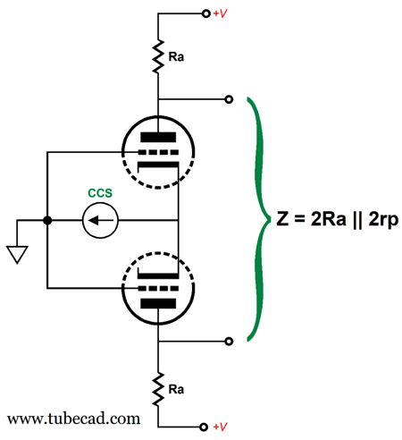
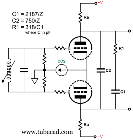
The added long-tail resistor (30k) and the 12µF capacitor (which can be a low voltage non-polarized electrolytic) allow for a large voltage difference between the triode plate voltages, while retaining the AC differential amplifier CMMR, thereby ignoring the shared power-supply noise between the two phases. The 12µF capacitor also imposes a 20Hz high-pass filter, which along with the two output coupling capacitors will limit the bad effects of record warp. By the way, the differential output gain is 46dB; the single-phase gain is 40dB. (The load impedance presented by a volume control will lower the gain. A workaround would be to add either two cathode followers or—more tube frugally—two emitter followers.) Figuring out the required RIAA-equalization capacitors and resistor values took some scratching, until I realized I only needed to know the differential output impedance of the input differential amplifier while being loaded down somewhat by the PNP transistors base impedance. A good starting point was to see that the triode plate resistance was in parallel with the plate resistor's resistance.
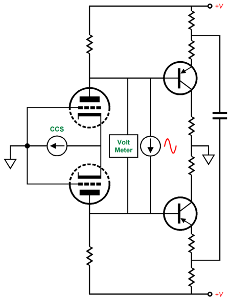
In SPICE, the easy test is to use an AC variable current source and a voltage meter to measure the AC voltage swing produced due to the AC current flow, dividing the peak voltage by the peak current.
Alas, performing the same test in reality would prove a major pain. The reality-based method would be to replace the RIAA equalization parts with a single 1% capacitor and to use an AC frequency generator to find the -3dB frequency at the outputs. Next, divide 159155 by that frequency, and divide that result again by the capacitor value in µfs. The final result will be the differential output impedance. In this example, the frequency will be 353.67Hz with the 0.1µF capacitor.
In this example, the output impedance was 4500 ohms. The math that follows is easy enough.
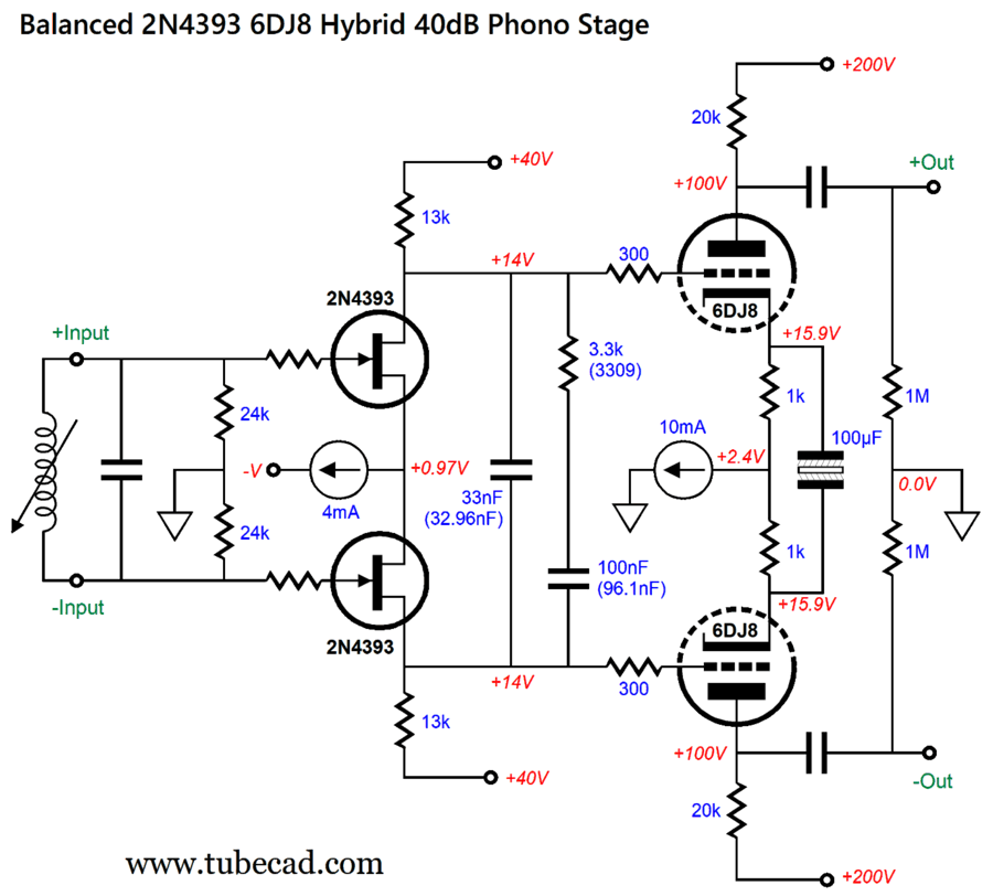
This got me thinking about a different sort of hybrid balanced phono stage, one with a FET input stage that cascades into a tube-based differential amplifier.
It took some fiddling with part values to get the readily available part values for the RIAA equalization network to work out. You are welcome.
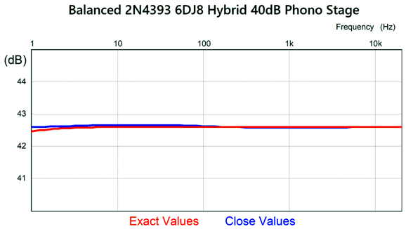
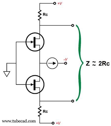
The close values cause a 0.15dB soft peak around 150Hz. Before you begin to fret, bear in mind that that far, far better than many high-audio, $$$$, phono preamps can deliver. Once again, I had to confront the problem of differential output impedance from the FET input stage. I knew that it would be close to twice the drain resistor value.
Fortunately, the following tube-based differential amplifier did not load down the input stage the way that the PNP transistor differential amplifier loaded the tube-based input stage. The tube-based differential amplifier will largely ignore the leaked power-supply noise from the FET input stage, but it offers effectively zero PSRR to its connection to its high-voltage power supply. One possible workaround is to add two Aikido cathode followers.
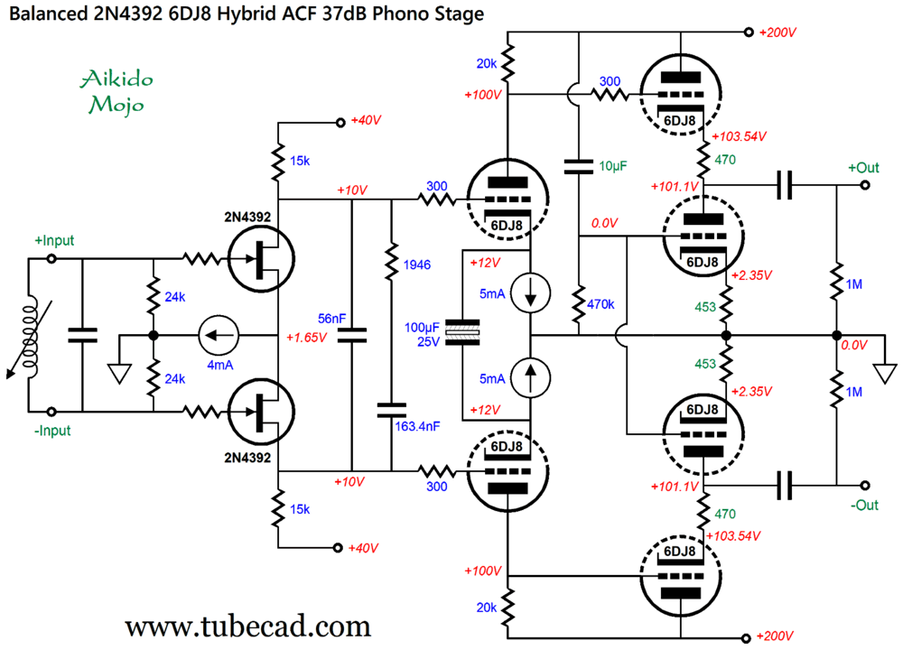
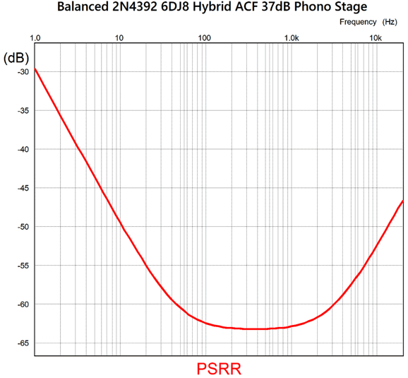
I switched to the 2N4392 FET, as its higher source voltage would allow using an IC constant-current source, such as the LM334. Note the dissimilar cathode resistor values in the ACF stages and the absence of a two-resistor voltage divider to feed the bottom triodes their sampling of power-supply noise. While it's hardly tube-frugal, this arrangement does work well at delivering a fine PSRR, as the following graph shows.
Bear in mind that this only applies to the high-voltage power-supply noise, with the assumption that the 40Vdc power supply for the FETs is blameless. On the other hand, we could forgo the use of a second differential amplifier.
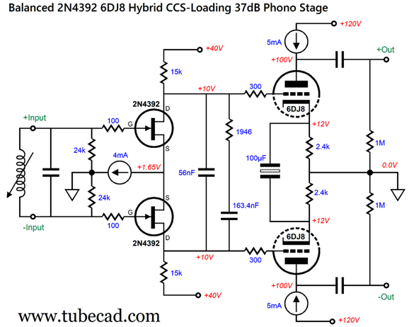
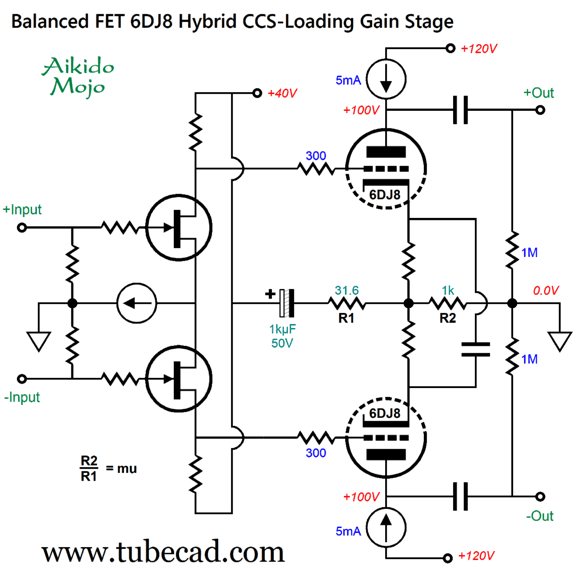
The 6DJ8-based second stage is shielded from the high-voltage power-supply noise by the two constant-current sources. Note the low B+ voltage for the tubes, a gift from the constant-current sources. Sadly, any leaked power-supply noise from the input FET differential amplifier will be amplified by the tubes. In other words, rather than getting a negative PSRR figure, we get a PSAF, a power-supply noise amplification factor. Not good. Here is my Aikido Mojo workaround.
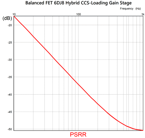
This is no longer a phono preamp, but a balanced hybrid gain stage. Why the change? I wanted to highlight the universal application of this Aikido-Mojo technique, where we purposely inject the FET's power-supply noise into the cathodes via the 1kµF capacitor and the two-resistor voltage divider made up from resistors R1 and R2. A triode's cathode offers greater gain than its grid by the following ratio mu (amplification factor) versus mu + 1. By making R1 mu times smaller in value than R2's resistance, we ensure the greatest PSRR enhancement. Here is the SPICE-generated graph.
This PSRR figure may not seem that high in value, but remember that we started with power-supply noise gain. Put differently, the reduction in power-supply noise is greater than the graph reveals. In addition, it is easy to build a low-voltage regulator for the FET input stage. What if we forgo the triodes and use FETs to deliver the desired gain? Well, we could get away with a much lower power-supply voltage, and we could place the electronics within a sealed metal enclosure, limiting RFI and microphonic-inducing sound from entering.
The negative power-supply rail might or might not be needed, depending on the FETs used in the input stage. Another possible topology replaces the NPN transistors with PNP transistors.
It's quite possible that all the CCSs shown in the schematic could be replaced by FETs configured as constant-current sources. Another possibility is to use low-noise dual-amplifier OpAmps in place of the FETs in the input stage.
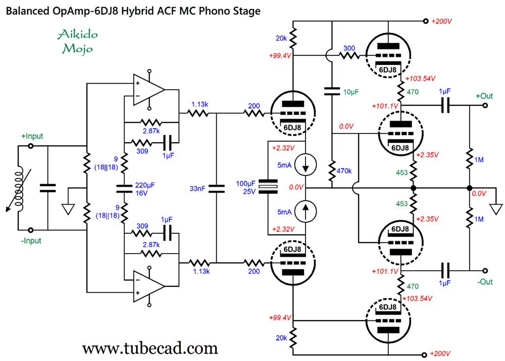
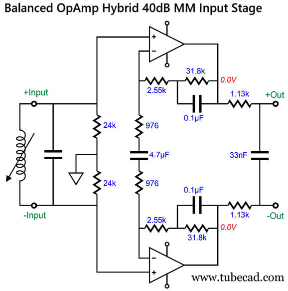
The RIAA equalization is now active-passive mix, as the needed low-frequency boost (3180µs and 318µs) is achieved by negative feedback OpAmps' negative-feedback loops, while the 75µs highs cutoff is handled passively by the 1.13k resistors and the 33nF capacitor. The two 1µF capacitors within the NFB loops may seem outrageously excessive in value; they aren't. Low resistor values compel inversely large capacitor values. Alas, this OpAmp arrangement only comes close to delivering true differential amplifier high CMRR. For example, a common-mode DC offset voltage will be passed on unattenuated to both outputs, but at least it is not amplified. Thus, the triode-based differential amplifier must supply the needed high CMRR. This is an MC phono preamp. If less gain is required, we can use the following input stage instead. (Note the smaller capacitor values and higher resistor values. Less gain means that we are less interested in lowest noise possible.)
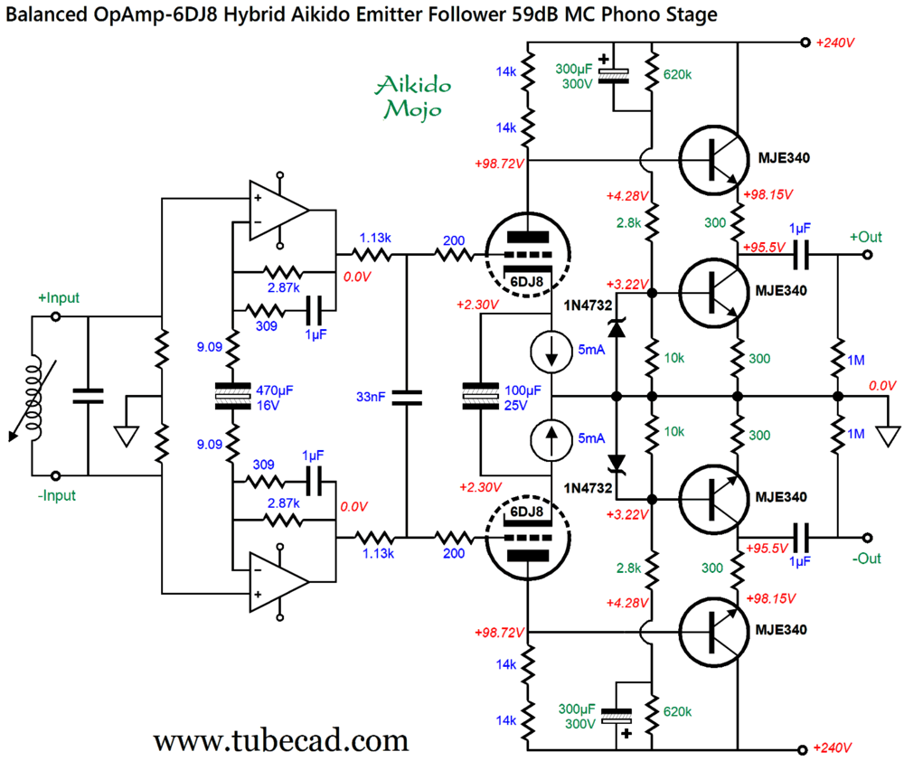
The Aikido cathode followers eliminate the power-supply noise from the outputs, but at the cost of many added tubes. A workaround would be to use two Aikido emitter followers instead.
The two 1N4732 zeners are there to protect the bottom MJE340 NPN transistors at turn-on, as the huge 300µF capacitors charge up slowly. Note the increased B+ voltage of 240Vdc, which allowed for larger-valued plate resistors and, thus, more gain. In SPICE simulations, the Aikido emitter followers delivered the goods in terms of PSRR.
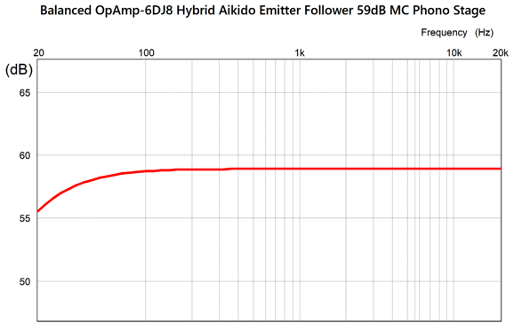
The RIAA equalization also delivered flat gain, with an intentional -3dB 20Hz low-frequency cutoff.
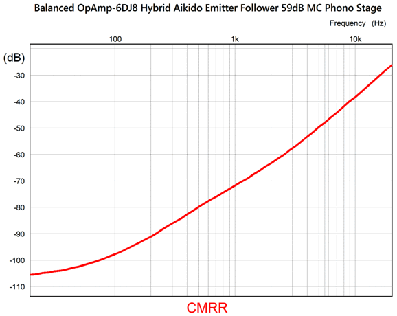
The remaining unanswered question was, How good is the CMRR? I need not have worried.
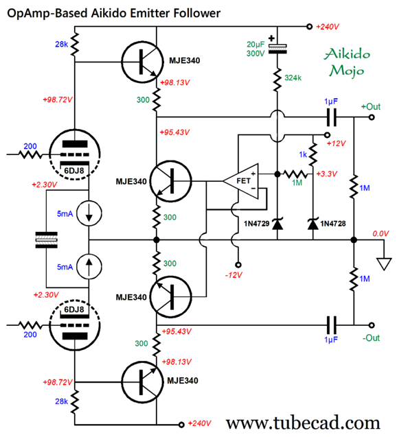
The wall-voltage frequency is where we want the deepest null. The more I thought about it, the less I liked the complexity of the Aikido emitter follower arrangement. We can exploit the ±12Vdc bipolar power supply and use an OpAmp to drive the bottom MJE340 bases, which also eliminates the need for huge-valued capacitors.
The zener on the right establishes the 3.3V reference voltage, while the one on the left limits the maximum positive and negative input voltages to the OpAmp's non-inverting input. Here is the PSRR graph for this variation:
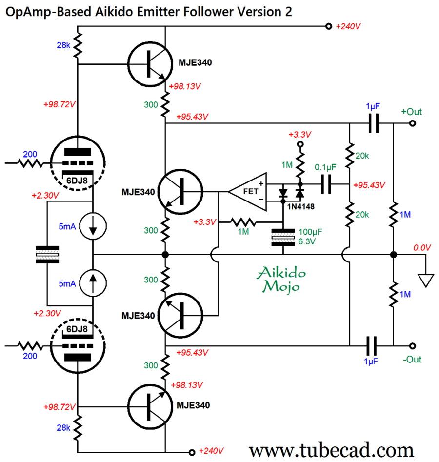
To be frank, I expected more. With an MC phono preamp we should expect and get more. In other words, I decided to try again. Here is the result.
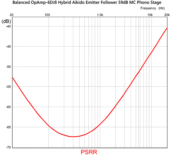
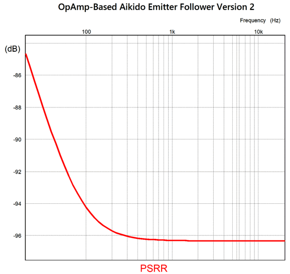
The two 1N4148 diodes protect the OpAmp's inputs. Note that there's no direct connection to the B+ voltage; instead, the two outputs before the output coupling capacitors are summed through the two 20k resistors and that signal is relayed via the 0.1µF coupling capacitor to the OpAmp's non-inverting input. Mind you, since the OpAmp drives the two inverting NPN transistors, this input effectively becomes an inverting input. With the OpAmp's inverting now effectively being its non-inverting input, the 100µF non-polarized capacitor grounds this input. In other words, this arrangement uses negative feedback to eliminate common-mode signals, such as leaked power-supply noise and furthers the balance of the two-phased outputs. The two out-of-phase output signals cancel, leaving only the equally shared power-supply noise. Here is the resulting PSRR graph.
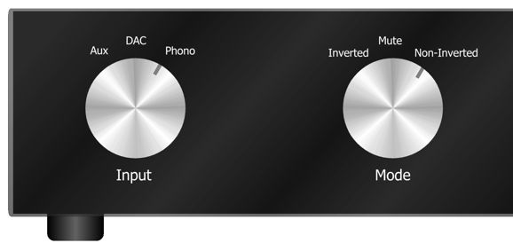
Not only is the 27dB improvement at 100Hz welcome, the extended and flat attenuation above 100Hz deserves our consideration. Do not forget that this PSRR is what is superimposed upon whatever efforts, such as high-voltage regulation, RC filters, chokes, that we employ to reduce the B+ voltage noise. All in all, I quite like this balanced hybrid phono preamp design. Moreover, the use of OpAmps allow for easy future upgrades, as long as ICs continue to be made in a non-surface-mount package. We can even use an inverting OpAmp stage to provide an inverted signal from an unbalanced input signal, such as tape a deck or tuner, while balanced outputs from the DAC and phono stage bypass the need.
Having a center mute position is ideal, as the ear requires a short silent pause before it can evaluate a flipping of phase. In addition, when playing LPs, it's great to be able to mute the output while we clean the stylus.
Music Recommendation: Baba Blues' Svenskt Glimmer Gemini AI informs us that:
It goes on to explain that
Well, the title is well chosen, as the album is a glimmering prize of a modern blues album.
//JRB
AI Summary This document discusses advanced audio amplifier and preamplifier design concepts, focusing on balanced versus unbalanced systems, noise reduction, phase reversal, and hybrid tube-transistor topologies. Advantages of Balanced Audio Transmission
Balanced Phono Preamplifier Concepts
Hybrid Tube and Transistor Amplifier Designs
Power Supply Noise Rejection Techniques
Use of OpAmps in Noise Suppression
Practical Considerations and Circuit Challenges
Music and Cultural Note
Did you enjoy my post? Do you want to see me make it to post 1,000? If so, think about supporting me at Patreon.
User Guides for GlassWare Software
For those of you who still have old computers running Windows XP (32-bit) or any other Windows 32-bit OS, I have setup the download availability of my old old standards: Tube CAD, SE Amp CAD, and Audio Gadgets. The downloads are at the GlassWare-Yahoo store and the price is only $9.95 for each program. So many have asked that I had to do it. WARNING: THESE THREE PROGRAMS WILL NOT RUN UNDER VISTA 64-Bit or WINDOWS 7, 8, and 10 if the OS is not 32-bit or if it is a 64-bit OS. I do plan on remaking all of these programs into 64-bit versions, but it will be a huge ordeal, as programming requires vast chunks of noise-free time, something very rare with children running about. Ideally, I would love to come out with versions that run on iPads and Android-OS tablets.
|
I know that some readers wish to avoid Patreon, so here is a PayPal button instead. Thanks. John Broskie
John Gives
Special Thanks to the Special 89 To all my patrons, all 89 of them, thank you all again. I want to especially thank
I am truly stunned and appreciative of their support. In addition I want to thank the following patrons:
All of your support makes a big difference. I would love to arrive at the point where creating my posts was my top priority of the day, not something that I have to steal time from other obligations to do. The more support I get, the higher up these posts move up in deserving attention.
If you have been reading my posts, you know that my lifetime goal is reaching post number one thousand. I have 363 more to go. My second goal was to gather 1,000 patrons. Well, that no longer seems possible to me, so I will shoot for a mighty 100 instead. Thus, I have just 11 patrons to go. Help me get there. Thanks.
New URL of the GlassWare website |
||||

.png)


| www.tubecad.com Copyright © 1999-2026 GlassWare All Rights Reserved |