| John Broskie's Guide to Tube Circuit Analysis & Design |
| May 13 2026 | Post Number 638 |
||||
Output Transformers and Crossovers
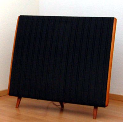
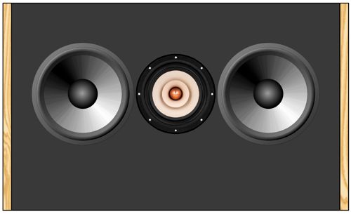
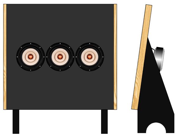
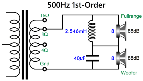
The assumption here is that the dipole loudspeaker need only cover frequencies above 100Hz, as two subwoofers cover the deep bass frequencies. In other words, a 100Hz high-pass active filter, probably 3rd-order, feeds the dipole's power amplifier its input signal. The 500Hz crossover frequency further unburdens the fullrange driver. The wavelength of 500Hz in air is about 27 inches (69cm), which allows us to get away with 1st-order crossover. The great thing about a 1st-order crossover is that it is transient-perfect due to its flat frequency and phase response. Its disadvantage is that it delivers little protection to a tweeter, but as this dipole uses a fullrange as the high-frequency driver that is far less of a problem. (If the only the fullrange driver is configured as dipole, the two woofers getting rear enclosures, then this loudspeaker could be used fullrange with subwoofer assistance.) All that the passive 500hz crossover needs is a 40µF capacitor and 2.55mH inductor, assuming 8-ohm loads. This implies that either two 4-ohm woofers are used in series or two 16-ohm woofers are used in parallel. First of all, although 16-ohm woofers are made, the selection is poor. In contrast, 4-ohm woofers abound. This got me thinking and wondering how I could use two 8-ohm woofers and—still—present an 8-ohm load to the power amplifier. My first thought was that I could use three identical fullrange drivers.
The trick is found in placing an 8-ohm power resistor in series with two of the fullrange drivers, bringing their impedance up to 16 ohms, and then placing these two series in parallel, bringing the impedance back down to 8 ohms. Amazingly enough, the SPL per watt remains the same. Yes, the 8-ohm resistors halve the voltage to the flanking drivers, which results in a -6dB drop in SPL; but as we have twice the radiating surface area, the SPL goes up by 6dB, resulting in unity, as -6dB is cancelled by the +6dB. Wouldn't the series resistor ruin the damping factor of the low-frequency drivers? "Ruin" is the wrong word; the correct word is "raise" the driver's Qes, which in turn raises its Qts. Most woofers are unsuitable for dipole use, as they come over-damped, i.e. low Qts, as in below 0.5, which is the critically-damped Q. The assumption behind making low-Qts woofers is that the speaker enclosure's trapped air will increase the woofer's Qtc (Q in cabinet) to something like 0.7 to 1.1. A Q of 0.7 sounds reserved; a Q of 1.1, punchy—if you like it, otherwise, booming.
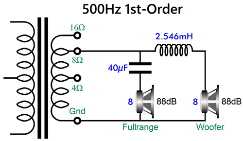
Another thought I had was that I could use a transformer to bring the 4-ohm load presented by two 8-ohm woofers in parallel up to 8 ohms with a 1.414:1 winding ratio. Where could I find such a transformer? I own a few. I bought those years ago at an electronic-surplus store in Silicon Valley. They were advertised as 170Vac transformers. I ran some test on them and was shocked by their stellar bandwidth and waveform fidelity. My guess was that since they were so well made and abided by the one-to-squareroot-of-2 ratio that they were intended for instrumentation use. In addition, since the dipole low-frequency bandwidth need only extend down to 100Hz, the transformer's effective power easily more than doubles. Well, this solution is great for me, but it is hardly universal in application. This, then, got me thinking about other audio transformers, such as those on tube-based power amplifiers. In days past, all output transformers sported at least four output taps, one for ground and for a 4-ohm, 8-ohm, and 16-ohm loudspeakers. This was a wonderful feature, as the amplifier's output stage got to see the same load impedance. Solid-state power amplifiers are almost universally direct coupled, making this feature unavailable to them, sadly. (Solid-state power amplifiers should hold a switch on the back panel that switches between two power transformer primary taps, one for full wall voltage and one for 70.7% of wall voltage. The full voltage is for 8-ohm loudspeaker; the 70.7%, 4-ohm loudspeakers. No more wattage doubling with 4-ohm speaker, but better sound and less heat and failures.) Let's look into the output transformer's multi taps.
A single-ended output transformer just lacks the center-tap, otherwise all is the same. In point of fact, the 4-ohm output tap is the secondary's center-tap.
The 8-ohm tap delivers 70.7% of the secondary AC voltage, while the 16-ohm tap delivers all the voltage. This means that the winding ratio from the 4-ohm tap to the ground tap is twice that of the 16-ohm tap's. Since the transformer's impedance ratio is equal to the winding ratio squared, the doubling in winding becomes four times greater in reflected impedance. Given a 1600-ohm output transformer, we see the following winding ratios.
While the 16-ohm tap delivers twice the peak voltage swing of that of the 4-ohm tap, the 4-ohm tap delivers twice the peak current of the 16-ohm tap. We are back to unity, as 2V x I/2 equals V/2 x 2I. Okay, now that we are comfortable with the output transformer, let's look into some possible arrangements, starting with two 8-ohm drivers.
The two drivers share both the same SPL and impedance. The crossover topology is the parallel arrangement. Here is the series version.
So far, nothing is out of the ordinary. Well, how about using two 4-ohm woofers?
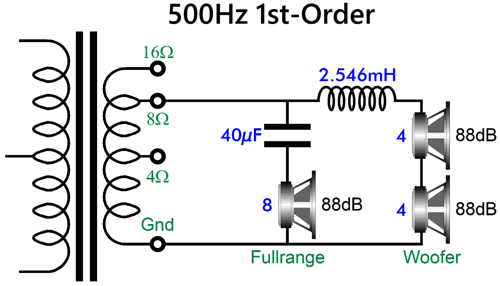
Whenever we use 4-ohm drivers, we have to be careful, as the SPL rating may not be accurate. Originally, SPL ratings were based on much sound output appeared at one meter with one watt of input power, which with 8-ohm drivers meant 2.828Vavg (4Vpk) of input signal. Alas, many lazy speaker-driver makers fail to use a 2Vavg (2.828pk) test signal (1W into 4 ohms), using the 8-ohm test voltage instead. In this example, I assume the lazy 8-ohm test voltage was used. Note that each woofer gets half the voltage, but still delivers 88dB due to the doubled cone area. What if we use two 8-ohm woofers instead? We must use the 16-ohm transformer output tap to maintain an 8-ohm load impedance.
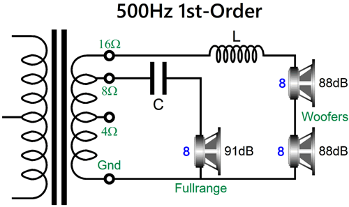
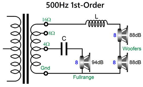
As far as the tube-based output stage is concerned, an 8ohm loudspeaker is attached to the transformer's secondary. Note the discrepancy in SPL between woofers and fullrange driver, 88dB versus 91dB. Each woofer sees 70.7% of the AC voltage that the fullrange driver sees at the crossover frequency of 500Hz, reducing each woofer's SPL by -3dB, resulting 85dB; but as there's two woofers, their output gains 6dB of SPL, which brings their combined output to 91dB, thereby matching the fullrange driver's SPL. The downside to this arrangement is that the crossover inductor must offer twice the inductance. High-quality inductors are not cheap.
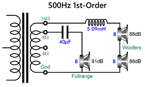
What if the fullrange driver offers an SPL 6dB higher than the woofers? We can use the 4-ohm tap to halve its signal.
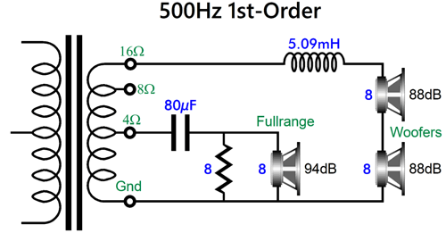
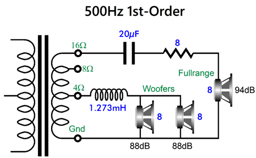
All the drivers see the same AC voltage at the crossover frequency of 500Hz, but as there's two woofers, their output gains 6dB of SPL, bringing their total in line with the fullrange driver's 94dB. The impedance presented to the output stage is not flat, as the 8-ohm fullrange driver reflects as a 3200-ohm load, not the intended 1600 ohms. The workaround is to shunt the fullrange driver with an 8-ohm power resistor.
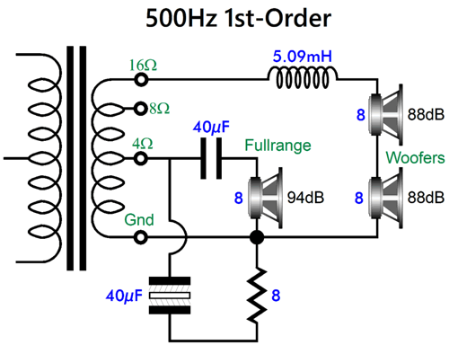
Now, we get a flat impedance, but at the cost of twice the capacitor value. High-quality, high-end crossover 80µF capacitors cost a fortune, as in $3260 for two 40µF Duelund Capacitor 40µF 100Vac CAST-Cu Series Copper Foil WPIO capacitors, which brings us to $6530 for two loudspeakers. Should be buy them? Only if you are either insanely rich or just insane. (If your reply is that only the best will do, then my rejoinder is, it's a pity that this standard does not apply to your brain. An obsession with either the most expensive or the cheapest reveals a damaged soul.) A sensible workaround is to two use two 40µF capacitors and one 8-ohm resistor. A Dayton Audio PMPC-40 40uF 250V Precision Audio capacitor only cost $28 and a non-polarized 40µF electrolytic capacitor (say a 22µF and 18µ in parallel) cost only a few dollars.
Another workaround would be to place both 8-ohm woofers in parallel and use the 8-ohm resistor in series with the fullrange driver.
All the drivers see the same AC voltage at the crossover frequency of 500Hz, but as there's two woofers, their output gains 6dB of SPL, bringing their total in line with the fullrange driver's 94dB. As I said before, having a driver's Qes go up is a good thing in a dipole loudspeaker. The big benefit to this arrangement is that we can skimp on crossover part values, as the woofer's combined 4-ohm impedance requires half the inductance, while the 16-ohm presented by the fullrange driver and resistor halves the needed capacitance.
We can purchase two Duelund Capacitor 20µF 100Vac CAST-Cu Series Copper Foil WPIO capacitors for less than $2000, which is considered beer budget by some audiophiles. This setup appeals to me greatly, if for no other reason that is so dang clever. Let's move on to something more conventional, a two-way loudspeaker with a woofer and tweeter.
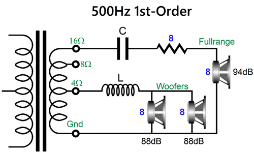
Perhaps, you have noticed that some high-end loudspeakers, such as those from Vandersteen and GR Research, are now sporting rear-firing tweeters. Why? Better sound and imaging. Well, we can use an output transformer to good effect with this arrangement.
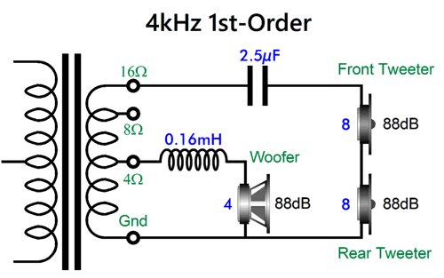
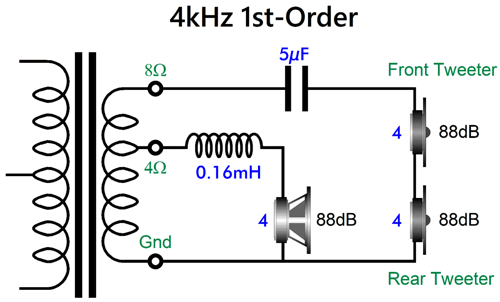
We use a 4-ohm woofer and two 8-ohm tweeters, with one tweeter firing forward, the other backwards. Once again, we realize crossover part savings, while still presenting an effectively 8-ohm load to the tube output stage. Note that all the drivers share the same SPL. (I would use a fullrange driver in this speaker, due to the 1st-order crossover.) Earlier, I mentioned that in the good-old days, output transformer offered 16-ohm output taps. Today, many new-production output transformers only hold 4-ohm and 8-ohm output taps. Well, we could use two 4-ohm tweeters with the 8-ohm tap and a 4-ohm woofer with the 4-ohm tap.
We still enjoy some crossover-capacitor savings, as 4-ohm tweeter crossing over at 4kHz requires a 10µF capacitor, and we got away with a 5µF capacitor, saving us hundreds of "Duelund" dollars.
Triad Wire
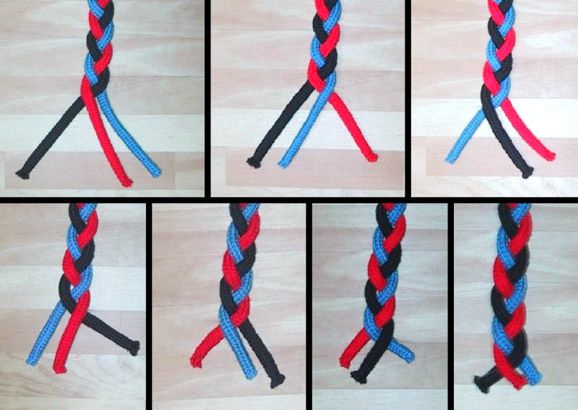
The nice thing about three wires is that we can easily make a braided cable out of the three wires.
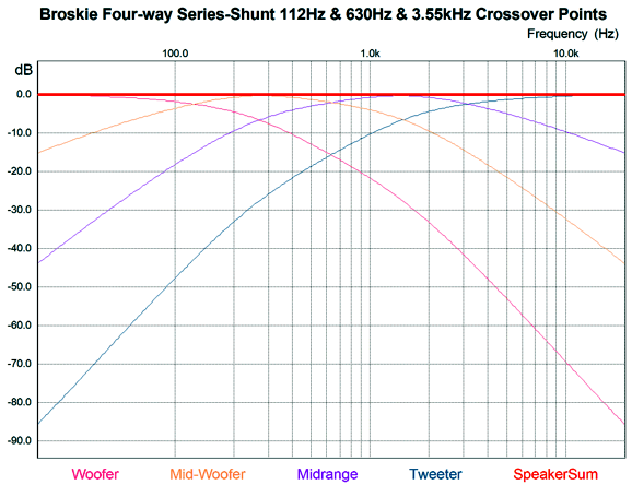
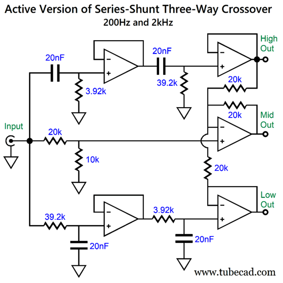
Active Version of Series-Shunt Three-Way Crossover
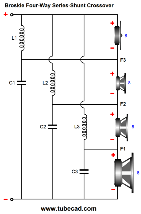
The tweeter sees all three crossover frequencies in cascade, making it cut-off slope begin with 1st-order, then 2nd-order, and ending with 3rd-order at the lowest audio frequencies. This is the topology for the four-way crossover.
Just using three capacitors and three inductors is quite parsimonious for a four-way crossover. Here is what I said in that post about this crossover:
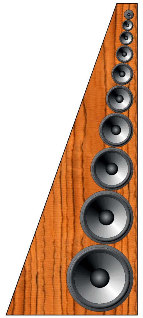
A ten-way loudspeaker may never have been tried before. Think of the marketing potential, as it could be labeled the One Octave ™ or the Decade Speaker ™, but perhaps the Deca-Dent Loudspeaker™ would be more apt. Just imagine the array of drivers: 18", 15", 12", 10", 8", 7", 6", 5", 4", 3", and 1" dome tweeter". Mercy. Nine crossover frequencies would be used: 40Hz, 80Hz, 160Hz, 320Hz, 640Hz, 1,250Hz, 2,500Hz, 5kHz, and 10kHz.
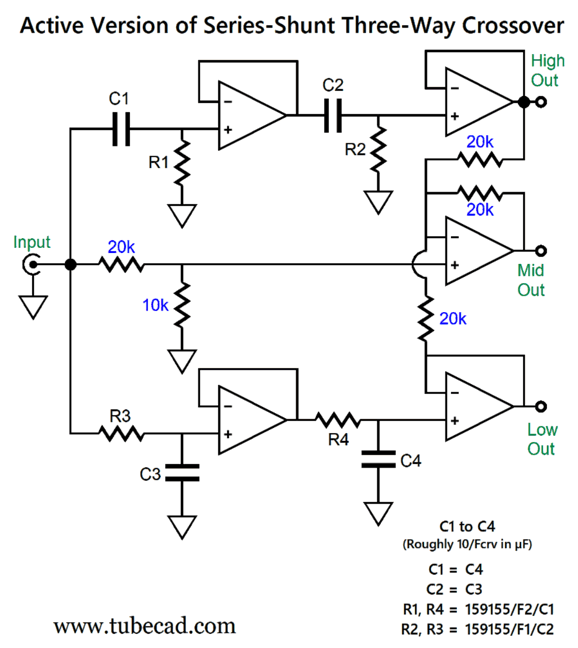
I have wondered how to create an active version of the series-shunt crossover. Since I am presently tri-amping, active three-way crossovers have been on my mind. My first (successful) stab at the active topology required six capacitors, which I deemed excessive. Here is my frugal four-capacitor version. (By the way, both versions used five OpAmps.)
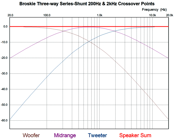
The trick was to deliver 1/3 of the input signal via the two-resistor voltage divider (20k and 10k resistors) to the midrange OpAmp's non-inverting input. Here is a design example with 200Hz and 2kHz crossover frequencies.
Music Recommendation: 24-Bit, 192kHz Music
Duke Ellington, Anatomy of a Murder
Shelly Manne, Empathy
(Be sure to listen to track number 7, "The Conference" //JRB Did you enjoy my post? Do you want to see me make it to post 1,000? If so, think about supporting me at Patreon.
AI Summary The document centers on the design and optimization of dipole loudspeakers, with a particular emphasis on crossover design, impedance matching, and the use of transformers. I also included notable examples and practical advice provided by the author. Key Points Summary
Example Implementation:
User Guides for GlassWare Software
For those of you who still have old computers running Windows XP (32-bit) or any other Windows 32-bit OS, I have setup the download availability of my old old standards: Tube CAD, SE Amp CAD, and Audio Gadgets. The downloads are at the GlassWare-Yahoo store and the price is only $9.95 for each program. So many have asked that I had to do it. WARNING: THESE THREE PROGRAMS WILL NOT RUN UNDER VISTA 64-Bit or WINDOWS 7, 8, and 10 if the OS is not 32-bit or if it is a 64-bit OS. I do plan on remaking all of these programs into 64-bit versions, but it will be a huge ordeal, as programming requires vast chunks of noise-free time, something very rare with children running about. Ideally, I would love to come out with versions that run on iPads and Android-OS tablets.
|
I know that some readers wish to avoid Patreon, so here is a PayPal button instead. Thanks. John Broskie
John Gives
Special Thanks to the Special 89 To all my patrons, all 89 of them, thank you all again. I want to especially thank
I am truly stunned and appreciative of their support. In addition I want to thank the following patrons:
All of your support makes a big difference. I would love to arrive at the point where creating my posts was my top priority of the day, not something that I have to steal time from other obligations to do. The more support I get, the higher up these posts move up in deserving attention.
If you have been reading my posts, you know that my lifetime goal is reaching post number one thousand. I have 362 more to go. My second goal was to gather 1,000 patrons. Well, that no longer seems possible to me, so I will shoot for a mighty 100 instead. Thus, I have just 11 patrons to go. Help me get there. Thanks.
New URL of the GlassWare website |
||||


| www.tubecad.com Copyright © 1999-2026 GlassWare All Rights Reserved |